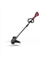
P48ST8 - String Trimmer Powerworks - Free user manual and instructions
Find the device manual for free P48ST8 Powerworks in PDF.


| Product type | Cordless String Trimmer |
| Brand | Powerworks |
| Model | P48ST8 |
| Power source | 48V lithium-ion battery (models 298513/2908613/2908713/2908813) |
| Weight (without battery) | 3.1 kg |
| No-load speed | 6500/5600 ±10% rpm (2 speeds) |
| Cutting diameter | 11" (279 mm) or 13" (330 mm) adjustable |
| Line diameter | 0.080" (2 mm) nylon |
| Cutting head | Tap & Go feed |
| Sound pressure level | 76 dB(A) (K=3 dB(A)) |
| Sound power level | 96 dB(A) guaranteed |
| Vibration level | 6.81 m/s² (k=1.5 m/s²) |
| Safety | Clear guard, line cutting blade, trigger with lock-off button, automatic shutdown in case of overload |
| Main functions | Cutting grass, small brush, vegetation near ground; line length adjustment by tapping on ground; two speeds |
| Maintenance and cleaning | Clean with a damp cloth and mild detergent; do not spray water on the motor; replace spool and line regularly |
| Spare parts and repairability | Spool, cutting line (2 mm nylon), cutting blade, guard, tap wheel, auxiliary handle |
| Warranty | 3 years on product, 2 years on batteries (private use) |
| Package contents | Machine, guard, edger guide, auxiliary handle, documentation |
| Country of origin | China (manufactured by Changzhou Globe Co., Ltd.) |
Frequently Asked Questions - P48ST8 Powerworks
User questions about P48ST8 Powerworks
0 question about this device. Answer the ones you know or ask your own.
Ask a new question about this device
Download the instructions for your String Trimmer in PDF format for free! Find your manual P48ST8 - Powerworks and take your electronic device back in hand. On this page are published all the documents necessary for the use of your device. P48ST8 by Powerworks.
USER MANUAL P48ST8 Powerworks
STE302
CE
Original Instructions / Übersetzung der Originalanweisungen / Traducción de las instrucciones originales / Traduzione delle istruzioni originali / Traduction des instructions d'origine / Vertaling van de originele gebruiksaanwijzing / Alkuperäisten ohjeiden käännös / Översättning av original instruktionerna / Produsentens instruksjoner / Oversættelse af de originale vejledninger / Překlad originálního návodu / Preklad originálneho návodu / Prevod originalnih navodil / Prijevod izvornih uputa / Az eredeti utasítás fordítása / Превод на оригинаналните инструкции / Orijinal Talimatlann Tercümesi / Originaalkasutusjuhendi tõlge
English
EN
1 Description.... 4
1.1 Purpose......4
1.2 Overview.... 4
2 Safety.... 4
3 Installation 4
3.1 Unpack the machine....4
3.2 Attach the guard....4
3.3 Attach the edge guide.... 4
3.4 Assemble the shaft....5
3.5 Attach the auxiliary handle.... 5
3.6 Install the battery pack.... 5
3.7 Remove the battery pack.... 5
4 Operation....5
4.1 Controls....5
4.2 Start the machine.... 5
4.3 Stop the machine.... 5
4.4 Adjust the length of the cutting line.... 5
4.5 Adjust the cutting diameter....5
4.6 Line cut-off blade....5
4.7 Operation tips....6
4.8 Cutting tips.... 6
5 Maintenance....6
5.1 General information....6
5.2 Clean the machine.... 6
5.3 Replace the spool....6
5.4 Replace the cutting line....6
5.5 Replace the bump knob.... 7
6 Transportation and storage...... 7
6.1 Move the machine....7
6.2 Store the machine.... 7
7 Troubleshooting......7
8 Technical data.... 8
9 Warranty....9
10 EC Declaration of conformity......9
1 DESCRIPTION
1.1 PURPOSE
This machine is used to cut grass, light weeds, and other similar vegetation at or around ground level. The cutting plane must be approximately parallel to the ground surface. You cannot use the machine to cut or chop hedges, shrubs, bushes, flowers and compost.
1.2 OVERVIEW
Figure 1 - 19.
| 1 | Rear handle |
| 2 | Lock-out button |
| 3 | Speed switch |
| 4 | Trigger |
| 5 | Auxiliary handle |
| 6 | Coupler |
| 7 | Edge guide |
| 8 | Cut-off blade |
| 9 | Guard |
| 10 | Screw hole |
| 11 | Release button |
| 12 | Lower shaft |
| 13 | Upper shaft |
| 14 | Positioning hole |
| 15 | Knob |
| 16 | Lower clamp |
| 17 | Battery release button |
| 18 | Spool cover |
| 19 | Spool |
| 20 | Tab |
| 21 | Line exit hole |
| 22 | Bump knob |
| 23 | Spool housing |
| 24 | Metal rod |
| A | Direction of rotation |
| B | Best cutting area |
| C | Dangerous cutting area |
2 SAFETY
WARNING
Make sure that you do/obey all safety instructions.
Refer to Safety Manual.
3 INSTALLATION
WARNING
Remove the battery pack from the machine before installation.
WARNING
Do not use accessories that are not recommended for this machine.
3.1 UNPACK THE MACHINE
▲ WARNING
Make sure that you correctly assemble the machine before use.
WARNING
- If the parts have damage, do not use the machine.
- If you do not have all the parts, do not operate the machine.
-
If the parts are damaged or missing, speak to the service center.
-
Open the package.
- Read the documentation in the box.
- Remove all the unassembled parts from the box.
- Remove the machine from the box.
- Discard the box and package in compliance with local regulations.
3.2 ATTACH THE GUARD
Figure 2.
WARNING
Do not touch the cut-off blade.
- Remove the screws from the trimmer head with a Phillips head screwdriver (not included).
- Put the guard onto the trimmer head.
- Align the screw holes on the guard with the screw holes on the trimmer head.
- Tighten the screws.
3.3 ATTACH THE EDGE GUIDE
Figure 4.
NOTE
The edge guide can limit the cutting range of the machine and decrease the risk of the damage caused by the rotating cutting line.
- Push the edge guide onto the trimmer head until it engages in the slots.
- The edge guide can be flipped up for storage.
3.4 ASSEMBLE THE SHAFT
Figure 3.
- Loosen the knob on the coupler.
- Push in the release button on the lower shaft.
- Align the release button with the positioning hole and move the two shafts.
- Turn the lower shaft until the button locks into the positioning hole.
- Tighten the knob.
3.5 ATTACH THE AUXILIARY HANDLE
Figure 5.
- Remove the screws from the handle with a Phillips screwdriver (not provided).
- Attach the auxiliary handle and lower clamp on the shaft.
- Set the auxiliary handle in the comfortable position.
- Tighten the screws.
3.6 INSTALL THE BATTERY PACK
Figure 6.
WARNING
- If the battery pack or charger is damaged, replace the battery pack or the charger.
- Stop the machine and wait until the motor stops before you install or remove the battery pack.
-
Read, know, and do the instructions in the battery and charger manual.
-
Align the lift ribs on the battery pack with the grooves in the battery compartment.
- Push the battery pack into the battery compartment until the battery pack locks into place.
- When you hear a click, the battery pack is installed.
3.7 REMOVE THE BATTERY PACK
Figure 6.
- Push and hold the battery release button.
- Remove the battery pack from the machine.
4 OPERATION
i IMPORTANT
Before you operate the machine, read and understand the safety regulations and the operation instructions.
WARNING
Be careful when you operate the machine.
4.1 CONTROLS
4.2 START THE MACHINE
Figure 7.
- Push the lock-out button and pull the trigger.
- Push the speed switch to the desired operating speed. Push the speed switch to position 1 for low speed or position 2 for high speed.
4.3 STOP THE MACHINE
Figure 7.
- Release the trigger to stop the machine.
4.4 ADJUST THE LENGTH OF THE CUTTING LINE
Figure 8.
While you operate the machine, the cutting line gets worn and shorter. You can adjust the length of the cutting line.
- Hit the trimmer head against the ground while you operate the machine.
- Line is automatically released and the cut-off blade cuts the excess length.
4.5 ADJUST THE CUTTING DIAMETER
Figure 9.
i NOTE
The machine is set at a 11 in. (279 mm) cutting diameter. You can adjust to a 13 in. (330 mm) cutting diameter.
Set the cutting diameter to 11 in. (279 mm) for greater runtime and 13 in. (330 mm) for a larger cutting area.
- Remove the battery pack.
- Remove the blade screws from the cut-off blade.
- Turn the cut-off blade 180°.
- Tighten the blade screws.
4.6 LINE CUT-OFF BLADE
Figure 9.
This trimmer is equipped with a line cut-off blade on the guard. The line cut off blade continuously trims the line to ensure a consistent and efficient cut diameter. Advance line whenever you hear the engine running faster than normal, or when trimming efficiency
diminishes. This will maintain best performance and keep line long enough to advance properly.
4.7 OPERATION TIPS
Figure 10.
WARNING
Keep clearance between the body and the machine.
WARNING
Do not operate the machine without guard in place.
Do these tips when you use the machine
- Keep the machine connected to the correctly worn harness.
- Keep a firm hold with the two hands on the machine while you operate the machine.
- Cut tall grass from the top down.
If grass winds around the trimmer head:
- Remove the battery pack.
- Remove the grass.
4.8 CUTTING TIPS
Figure 11.
- Tilt the machine toward the area to be cut. Use the tip of the cutting line to cut grass.
- Move the machine from right to left to prevent thrown debris toward the operator.
- Do not cut in the dangerous area.
- Do not force the trimmer head into uncut grass.
- Wire and picket fences cause cutting line wear and breakage. Stone and brick walls, curbs, and wood can wear the cutting line quickly.
5 MAINTENANCE
i IMPORTANT
Read and understand the safety regulations and the maintenance instructions before you clean, repair or do the maintenance work on the machine.
i IMPORTANT
Make sure that all nuts, bolts and screws are tight. Examine regularly that you install the handles tightly.
i IMPORTANT
Use only the replacement parts and accessories of the initial manufacturer.
5.1 GENERAL INFORMATION
i IMPORTANT
Only your dealer or approved service center can do the maintenance that is not given in this manual.
Before the maintenance operations:
- Stop the machine.
- Remove the battery pack.
- Cool the motor.
- Store the machine in cool and dry place.
- Use correct clothing, protective gloves and safety glasses.
5.2 CLEAN THE MACHINE
- Clean the machine after use with a moist cloth dipped in neutral detergent.
- Do not use aggressive detergents or solvents to clean the plastic parts or handles.
- Keep the trimmer head free of grass, leaves, or excessive grease.
- Keep the air vents clean and free of debris to avoid overheating and damage to the motor or the battery.
- Do not spray water onto the motor and electrical components.
5.3 REPLACE THE SPOOL
Figure 12 - 17.
- Pull and remove the spool cover.
- Remove the remaining spool.
-
Put the spool in the spool cover.
-
Push the tabs on the sides of the trimmer head at the same time.
NOTE
Make sure that the cutting line is in the slot on the new spool, and is extended approximately 15 cm before you install the new spool.
- Put the ends of the cutting lines through the holes.
- Extend the cutting line to release it from the guide slot in the spool.
- Install the spool and spool cover onto the trimmer head.
- Push the spool cover until it clicks into position.
5.4 REPLACE THE CUTTING LINE
Figure 18.
i NOTE
Remove the remaining cutting line on the spool.
i NOTE
Use only with the nylon cutting line of 0.080" (2 mm) diameter.
- Cut a piece of cutting line approximately 3m long.
- Bend the line at the midpoint and hook the loop into the slot in the center rim of the spool. Make sure that the line snaps into position in the slot.
- With your finger between the lines, wind the lines equally and tightly around the spool in the indicated direction.
- Put the lines in the guide slots.
- Do not wind the lines beyond the edge of the spool.
5.5 REPLACE THE BUMP KNOB
Figure 19.
- Push the tabs on the sides of the trimmer head at the same time.
- Pull and remove the spool cover.
- Remove the spool.
- Hold the bump knob and pry it out with a metal rod (not provided).
- Put the new bump knob into the spool housing.
6 TRANSPORTATION AND STORAGE
6.1 MOVE THE MACHINE
When you move the machine, you must:
- Wear gloves.
- Stop the machine.
- Remove the battery pack and charge it.
- Assemble the blade guard.
6.2 STORE THE MACHINE
- Remove the battery pack from the machine.
- Make sure that children cannot come near the machine.
- Keep the machine away from corrosive agents such as garden chemicals and de-icing salts.
- Secure the machine during transportation to prevent damage or injury. Clean and examine the machine for any damage.
7 TROUBLESHOOTING
| Problem Possible Cause Solution | ||
| The machine does not start when you push the trigger. | No electrical contact between the machine and the battery pack. | 1. Remove battery pack.2. Check contact and install the battery pack again. |
| The battery pack is depleted. | Charge the battery pack. | |
| The lock-out button and trigger are not pushed at the same time. | 1. Pull the lock-out button and hold it.2. Pull the trigger to start the machine. | |
| The machine stops when you cut. | The guard is not attached to the machine. | Remove the battery pack and attach the guard to the machine. |
| Heavy cutting line is used. | Use only with the nylon cutting line of 0.080" (2 mm) diameter. | |
| The grass winds around the motor shaft or the trim-mer head. | 1. Stop the machine.2. Remove the battery pack.3. Remove the grass from the motor shaft and trimmer head. | |
| The motor is overloaded. | 1. Remove the trimmer head from the grass.2. The motor will recov-er to work as soon as the load is removed.3. When you cut, move the trimmer head in and out of the grass to be cut and remove no more than 8" in pass. | |
| The battery pack or machine is too hot. | 1. Cool the battery pack until its function returns to normal.2. Cool the machine for approximately 10 min-utes. | |
| The battery pack is disconnected from the tool. | Install the battery pack again. | |
| The battery pack is depleted. | Charge the battery pack. | |
| The line does not forward. | Lines are welded to themselves. | Lubricate with silicone spray. |
| Not enough line on spool. | Install more line. | |
| Lines are worn too short. | Advance the cutting line. | |
| Lines are tan-gled on spool. | 1. Remove the lines from the spool.2. Wind the lines. | |
| Problem Possible Cause Solution | ||
| The line keeps breaking. | The machine is used incorrectly. | 1. Cut with the tip of the line, avoid stones, walls and other hard objects.2. Advance the cutting line regularly to keep full cutting width. |
| The grass winds around the trimmer head and motor housing. | Cut tall grass at ground level. | 1. Cut tall grass from the top down.2. Remove no more than 8" in each pass to prevent wrapping. |
| The line does not cut well. | The cut-off blade becomes dull. | Sharpen the cut-off blade with a file or replace it. |
| Vibration increases obviously. | The line is worn down at one side and not advanced in time. | Make sure that the line at two sides is normal. Advance the line. |
8 TECHNICAL DATA
| Voltage 48 V | |
| No load speed | 6500/5600±10% RMP |
| Cutting head Bump feed | |
| Cutting line diameter | 0.080" (2 mm) |
| Cutting path diameter | 11/13 in. (279/330 mm) |
| Weight (without battery pack) | 3.1 kg |
| Measured sound pressure level | LpA=<76 dB(A), KpA=3 dB(A) |
| Measured sound power level | LwA=<94 dB(A) |
| Guaranteed sound power level | LwA.d=96 dB(A) |
| Vibration 6.81 m/s | 2,k=1.5 m/s2 |
| Battery model 298513 | /2908613/2908713/2908813 |
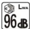
Noise value.
9 WARRANTY
(The full warranty terms and conditions can be found on Powerworks® webpage)
The Powerworks® warranty is 3 years on the product, and 2 years on batteries (consumer/private usage) from the date of purchase. This warranty covers manufacturing faults. A faulty product under warranty might be either repaired or replaced. A unit that has been misused or used in other ways then described in the owner's manual might be rejected for warranty. Normal wear, and wear parts are not considered as warranty. The original manufacturer warranty is not affected by any additional warranty offered by a dealer or retailer.
A faulty product must be returned to the point of purchase in order to claim for warranty, together with the proof of purchase (receipt).
10 EC DECLARATION OF CONFORMITY
Name and address of the manufacturer:
Name: Changzhou Globe Co., Ltd.
Address: No. 65 (3-4) Xinggang Rd., Zhonglou Zone, Changzhou 213101 China.
Name and address of the person authorised to compile the technical file:
Name: Peter Söderström
Address: Propellergatan 1, 211 15 Malmö, Schweden
Herewith we declare that the product
Category: String trimmer
Model: P48ST8
Serial number: See product rating label
Year of Construction: See product rating label
- is in conformity with the relevant provisions of the Machinery Directive 2006/42/EC.
• is in conformity with the provisions of the following other EC-Directives:
• 2014/30/EU (EMC-Directive)
• 2000/14/EC (Noise Directive) incl. modifications(2005/88/EC)
Furthermore, we declare that the following (parts/clauses of) European harmonised standards have been used:
- EN 60335-1; EN 50636-2-91; EN 62233; EN 55014-1; EN 55014-2 EN ISO 3744; ISO 11904; EN ISO 11806-1.
String trimmer
Measured sound power level: <94 dB(A)
Guaranteed sound power level: 96 dB(A)
Conformity assessment method to Annex VI / Directive 2000/14/EC.
Place, date: Signature: Ted Qu, Quality Director 27/10/2018
Ted au
Deutsch
DE
Adresse: No. 65 (3-4) Xinggang Rd., Zhonglou Zone, Changzhou 213101 China.
6.1 DÉPLACEMENT DE LA MACHINE
10 D CÉCALARATION DE CONEORMITÉ CE
Adresse : No. 65 (3-4) Xinggang Rd., Zhonglou Zone, Changzhou 213101 Chine.
• 2014/30/UE (Directive CEM)
• 2000/14/CE (Directive Bruit) modifications includes (2005/88/CE)
Adres: No. 65 (3-4) Xinggang Rd., Zhonglou Zone, Changzhou 213101 China.
6 TRANSPORT OCH FÖRVARING
6.1 FLYTTA MASKINEN
Adress: No. 65 (3-4) Xinggang Rd., Zhonglou Zone, Changzhou 213101, Kina.
Adresse: No. 65 (3-4) Xinggang Rd., Zhonglou Zone, Changzhou 213101, Kina.
5.4 UDSKIFT KLIPPESNOREN
Figur 18.
i BEMAERK
Cím: No. 65 (3-4) Xinggang Rd., Zhonglou Zone, Changzhou 213101 China.
Adres: No. 65 (3-4) Xinggang Rd., Zhonglou Zone, Changzhou 213101 Çin.
Aadress: No. 65 (3-4) Xinggang Rd., Zhonglou Zone, Changzhou 213101, Hiina.

- ENGLISH
- 1 DESCRIPTION
- 1.1 PURPOSE
- 1.2 OVERVIEW
- 2 SAFETY
- WARNING
- 3 INSTALLATION
- 3.1 UNPACK THE MACHINE
- ▲ WARNING
- 3.2 ATTACH THE GUARD
- 3.3 ATTACH THE EDGE GUIDE
- NOTE
- 3.4 ASSEMBLE THE SHAFT
- FIGURE 3
- 3.5 ATTACH THE AUXILIARY HANDLE
- FIGURE 5
- 3.6 INSTALL THE BATTERY PACK
- FIGURE 6
- 3.7 REMOVE THE BATTERY PACK
- 4 OPERATION
- I IMPORTANT
- 4.1 CONTROLS
- 4.2 START THE MACHINE
- FIGURE 7
- 4.3 STOP THE MACHINE
- 4.4 ADJUST THE LENGTH OF THE CUTTING LINE
- FIGURE 8
- 4.5 ADJUST THE CUTTING DIAMETER
- FIGURE 9
- I NOTE
- 4.6 LINE CUT-OFF BLADE
- 4.7 OPERATION TIPS
- 4.8 CUTTING TIPS
- 5 MAINTENANCE
- 5.1 GENERAL INFORMATION
- 5.2 CLEAN THE MACHINE
- 5.3 REPLACE THE SPOOL
- 5.4 REPLACE THE CUTTING LINE
- 5.5 REPLACE THE BUMP KNOB
- FIGURE 19
- 6 TRANSPORTATION AND STORAGE
- 6.1 MOVE THE MACHINE
- 6.2 STORE THE MACHINE
- 9 WARRANTY
- 10 EC DECLARATION OF CONFORMITY
- DEUTSCH
- DE
- 6.1 DÉPLACEMENT DE LA MACHINE
- 10 D CÉCALARATION DE CONEORMITÉ CE
- 6 TRANSPORT OCH FÖRVARING
- 6.1 FLYTTA MASKINEN
- 5.4 UDSKIFT KLIPPESNOREN
- I BEMAERK
Brand : Powerworks
Model : P48ST8
Category : String Trimmer