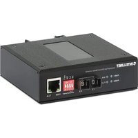
508964 - Audio/video converter Intellinet - Free user manual and instructions
Find the device manual for free 508964 Intellinet in PDF.


| Product Type | Ethernet to Fiber Optic Media Converter |
| Brand | Intellinet |
| Model | 508964 |
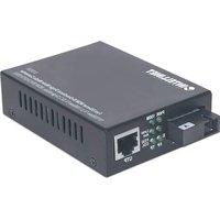
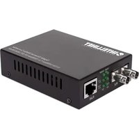
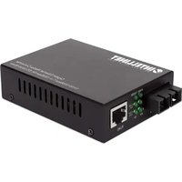
| Connectivity | 1× RJ45 10/100Base-TX port (100 m max), 1× Multimode SC 100Base-FX fiber port (2 km max) |
| Fiber Type | Multimode SC |
| Power Supply | Dual redundant DC input 12-56 V via screw terminal block |
| Power Consumption | Not specified |
| Dimensions (W×D×H) | Approximately 94 × 70 × 26 mm (estimated slim profile) |
| Weight | Approximately 200 g (estimated metal casing) |
| Housing Material | Metal IP40 (protection rating) |
| Mounting | DIN rail (accessory included) or flat surface mounting |
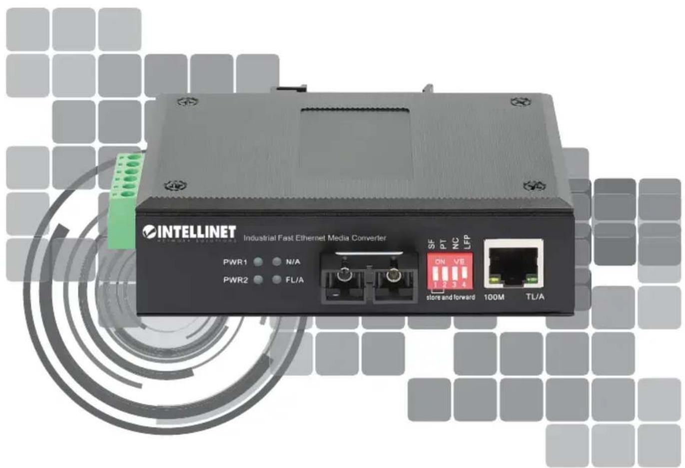
| LED Indicators | PWR1/PWR2, FL/A (fiber), TL/A (RJ45), 100M (speed) |
| DIP Switches | PT/SF (transfer mode) and NC/LFP (Link Fault Pass Through) |
| Transfer Modes | Store-and-Forward, Modified Cut-Through, Converter |
| Maximum RJ45 Distance | 100 m |
| Maximum Fiber Distance | 2 km (multimode) |
| Operating Temperature | Not specified (industry typical -10 to 60 °C) |
| Certifications | CE (Directives 2014/30/EU and 2014/35/EU) |
| Maintenance | Clean with a dry, non-abrasive cloth. Do not use solvents. |
| Safety | Disconnect power before any intervention. Maintain ventilation distances (25 mm). |
| Spare Parts / Repairability | No spare parts available. In case of failure, contact technical support. |
Frequently Asked Questions - 508964 Intellinet
User questions about 508964 Intellinet
0 question about this device. Answer the ones you know or ask your own.
Ask a new question about this device
Download the instructions for your Audio/video converter in PDF format for free! Find your manual 508964 - Intellinet and take your electronic device back in hand. On this page are published all the documents necessary for the use of your device. 508964 by Intellinet.
USER MANUAL 508964 Intellinet
Industrial Fast Ethernet Media Converter Instructions
Model 508964 (IMCI-MMSCF2KM)
Important: Read before use. • Important: Leer antes de usar.
For additional benefits:
Scan to register your product warranty

or go to: register.intellinet-network.com/r/508964
Media converters connect two Ethernet networks over a longer distance using fiber optic cable.
Features
One 10/100 RJ45 port supporting a maximum distance of 100m (300 ft.)
- One 100Base-FX fiber SC multi-mode port supporting a maximum distance of 2km (1.24 mi.)
- IP40 slim-type metal housing to withstand harsh industrial conditions
- Option for DIN-rail installation
- Two redundant DC inputs (12 - 56 V) with I/O terminal block
For specifications, visit intellinetnetwork.com. Register your product at register.intellinet-network.com/r/508964 or scan the QR code on the cover.

Placement
Desktop Installation
Prior to use, place/position the device:
- on a level surface that can support the device with at least 25mm (approx. 1'' ) of clearance for ventilation;
- away from sources of electrical noise: radios, transmitters, broadband amplifiers;
- within 100m (approx. 328 ) of network devices it's to be connected to.
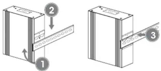
DIN-Rail Installation
1 Angle spring of mounting clip over top lip of DIN rail.
2 Push device down till clip clicks onto rail.
3 Ensure installation is stable.

Connections
Twisted Pair - RJ45
Connect the UTP port of the media converter to an RJ45 port on the network (e.g., to an Ethernet switch). Cat5e or better cabling is recommended.
Fiber Optic
As shown, two fiber optic cables need to be connected between two ideally identical media converters. Make a connection from Media Converter 1 TX to Media Converter 2 RX, and from Media Converter 1 RX to Media Converter 2 TX. Maximum length and fiber cable specification depend on the model. (See Models.)
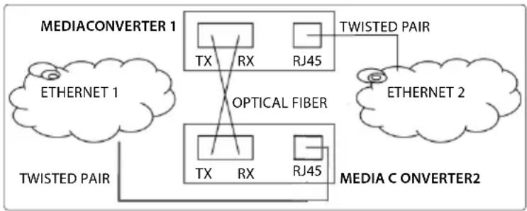
Example

Power
Terminal Block Installation
NOTE: Ensure all power is off/disconnected before beginning!
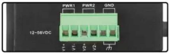
1 Loosen appropriate screws. Insert bare power-supply wires into appropriate terminals (positive wire into positive [V1 + ] terminal, negative wire into negative [V1-] terminal, ground wire to ground [GND] terminal).
2 Tighten appropriate screws to secure wires. Repeat these steps for a second power supply if desired (V2 + ,V2 - ,GND)
3 Install block into the device.

Front panel
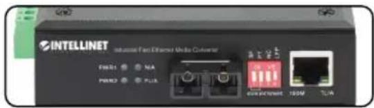
| LED Color Status Description | ||
| PWR1/PWR2 Green | On Power channel is powered. | |
| Off Power channel is not powered. | ||
| FL/A Green | On Fiber port is connected. | |
| Off Fiber port is not connected. | ||
| Flashing Sending or receiving data. | ||
| 100M Yellow | On 100 Mbps speed | |
| Off 10 Mbps speed | ||
| TL/A Green | On Valid port connection | |
| Off Connection not established. | ||
| Flashing Sending or receiving data. | ||
DIP Switch - PT/SF
| PT SF Function Description | |||
| OFF | OFF | Store and Forward mode | Frames are stored in the memory and checked for errors. If the frame passes the check, it is forwarded to the appropriate port. Note: Function may cause latency. |
| ON | OFF | Modified Cut Through mode | Checks the first 64 bytes of a frame, and if no issue, frame is forwarded to the destination address. |
| OFF | ON | Converter mode | Frames are forwarded as soon as the destination address is identified. Note: Function helps reduce latency and saves buffer space, but may forward bad frames which can create broadcast storms. |
| ON | ON | ||
DIP Switch - NC/LFP
| Switch | Position | Description |
| NC | Unused | |
| LFP | ON | Link Fault Pass Through enabled: Devices on a link must acknowledge that they are online before data can be transmitted. When one of the devices doesn’t respond, data cannot be sent. |
| OFF | Link Fault Pass Through disabled |
(Applicable In The European Union And Other European Countries With Separate Collection Systems)
ENGLISH: This symbol on the product or its packaging

means that this product must not be treated as unsorted household waste. In accordance with
EU Directive 2012/19/EU on Waste Electrical and
This equipment has been tested and found to comply with the limits for a Class A digital device, pursuant to Part 15 of the Federal Communications Commission (FCC) Rules. These limits are designed to provide reasonable protection against harmful interference when the equipment is operated in a commercial environment. This equipment generates, uses and can radiate radio frequency energy, and if not installed and used in accordance with the instruction manual may cause harmful interference to radio communications.
Operation of this equipment in a residential area is likely to cause harmful interference, in which case the user will be required to correct the interference at his own expense. Any changes or modifications made to this equipment without the approval of the manufacturer could result in the product not meeting the Class A limits, in which case the FCC could void the user's authority to operate the equipment.
CE
ENGLISH : This device complies with the requirements of CE 2014/30/EU (UKCA Electromagnetic Compatibility Regulations 2016) and / or 2014/35/EU (UKCA Electrical Equipment [Safety] Regulations 2016). The Declaration of Conformity for is available at:
support.intellinet-network.com/barcode/508964





intellinetnetwork.com
All trademarks and trade names are the property of their respective owners. © IC Intracom. All rights reserved. Intellinet Network Solutions is a trademark of IC Intracom, registered in the U.S. and other countries.
Brand : Intellinet
Model : 508964
Category : Audio/video converter