GKF 18V-8 Professional - Milling machine BOSCH - Free user manual and instructions
Find the device manual for free GKF 18V-8 Professional BOSCH in PDF.

User questions about GKF 18V-8 Professional BOSCH
0 question about this device. Answer the ones you know or ask your own.
Ask a new question about this device
Download the instructions for your Milling machine in PDF format for free! Find your manual GKF 18V-8 Professional - BOSCH and take your electronic device back in hand. On this page are published all the documents necessary for the use of your device. GKF 18V-8 Professional by BOSCH.
USER MANUAL GKF 18V-8 Professional BOSCH
natural_image
3D rendered mechanical device with no visible text or symbolsen Original instructions
fr Notice originale
pt Manual original
English ...... Page 10
Français Page 17

natural_image
Mechanical assembly diagram showing a bolted joint inserted into a housing (no text or symbols visible)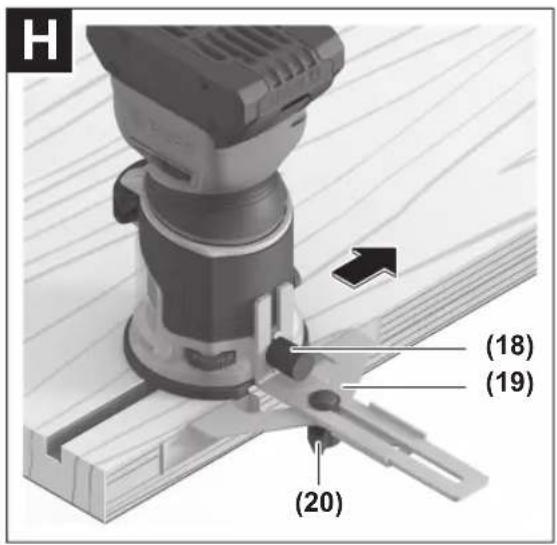

6
natural_image
Technical line drawing of a mechanical assembly with gears and mounting base (no text or symbols)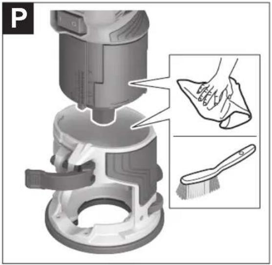
8
S
English
Safety Instructions
General Power Tool Safety Warnings
WARNING
Read all safety warnings, instructions, illustrations and specifica-
tions provided with this power tool. Failure to follow all instructions listed below may result in electric shock, fire and/or serious injury.
Save all warnings and instructions for future reference.
The term "power tool" in the warnings refers to your mains-operated (corded) power tool or battery-operated (cordless) power tool.
Work area safety
▶ Keep work area clean and well lit. Cluttered or dark areas invite accidents.
▶ Do not operate power tools in explosive atmospheres, such as in the presence of flammable liquids, gases or dust. Power tools create sparks which may ignite the dust or fumes.
▶ Keep children and bystanders away while operating a power tool. Distractions can cause you to lose control.
Electrical safety
▶ Power tool plugs must match the outlet. Never modify the plug in any way. Do not use any adapter plugs with earthed (grounded) power tools. Unmodified plugs and matching outlets will reduce risk of electric shock.
▶ Avoid body contact with earthed or grounded surfaces, such as pipes, radiators, ranges and refrigerators. There is an increased risk of electric shock if your body is earthed or grounded.
▶ Do not expose power tools to rain or wet conditions. Water entering a power tool will increase the risk of electric shock.
▶ Do not abuse the cord. Never use the cord for carrying, pulling or unplugging the power tool. Keep cord away from heat, oil, sharp edges or moving parts.
Damaged or entangled cords increase the risk of electric shock.
▶ When operating a power tool outdoors, use an extension cord suitable for outdoor use. Use of a cord suitable for outdoor use reduces the risk of electric shock.
▶ If operating a power tool in a damp location is unavoidable, use a residual current device (RCD) protected supply. Use of an RCD reduces the risk of electric shock.
Personal safety
▶ Stay alert, watch what you are doing and use common sense when operating a power tool. Do not use a power tool while you are tired or under the influence of drugs, alcohol or medication. A moment of inatten-
tion while operating power tools may result in serious personal injury.
▶ Use personal protective equipment. Always wear eye protection. Protective equipment such as a dust mask, non-skid safety shoes, hard hat or hearing protection used for appropriate conditions will reduce personal injuries.
▶ Prevent unintentional starting. Ensure the switch is in the off-position before connecting to power source and/or battery pack, picking up or carrying the tool. Carrying power tools with your finger on the switch or energising power tools that have the switch on invites accidents.
Remove any adjusting key or wrench before turning the power tool on. A wrench or a key left attached to a rotating part of the power tool may result in personal injury.
▶ Do not overreach. Keep proper footing and balance at all times. This enables better control of the power tool in unexpected situations.
▶ Dress properly. Do not wear loose clothing or jewellery. Keep your hair and clothing away from moving parts. Loose clothes, jewellery or long hair can be caught in moving parts.
▶ If devices are provided for the connection of dust extraction and collection facilities, ensure these are connected and properly used. Use of dust collection can reduce dust-related hazards.
Do not let familiarity gained from frequent use of tools allow you to become complacent and ignore tool safety principles. A careless action can cause severe injury within a fraction of a second.
Power tool use and care
▶ Do not force the power tool. Use the correct power tool for your application. The correct power tool will do the job better and safer at the rate for which it was designed.
▶ Do not use the power tool if the switch does not turn it on and off. Any power tool that cannot be controlled with the switch is dangerous and must be repaired.
▶ Disconnect the plug from the power source and/or remove the battery pack, if detachable, from the power tool before making any adjustments, changing accessories, or storing power tools. Such preventive safety measures reduce the risk of starting the power tool accidentally.
▶ Store idle power tools out of the reach of children and do not allow persons unfamiliar with the power tool or these instructions to operate the power tool. Power tools are dangerous in the hands of untrained users.
- Maintain power tools and accessories. Check for misalignment or binding of moving parts, breakage of parts and any other condition that may affect the power tool's operation. If damaged, have the power tool repaired before use. Many accidents are caused by poorly maintained power tools.
▶ Keep cutting tools sharp and clean. Properly maintained cutting tools with sharp cutting edges are less likely to bind and are easier to control.
▶ Use the power tool, accessories and tool bits etc. in accordance with these instructions, taking into account the working conditions and the work to be performed. Use of the power tool for operations different from those intended could result in a hazardous situation.
▶ Keep handles and grasping surfaces dry, clean and free from oil and grease. Slippery handles and grasping surfaces do not allow for safe handling and control of the tool in unexpected situations.
Battery tool use and care
▶ Recharge only with the charger specified by the manufacturer. A charger that is suitable for one type of battery pack may create a risk of fire when used with another battery pack.
▶ Use power tools only with specifically designated battery packs. Use of any other battery packs may create a risk of injury and fire.
When battery pack is not in use, keep it away from other metal objects, like paper clips, coins, keys, nails, screws or other small metal objects, that can make a connection from one terminal to another. Shorting the battery terminals together may cause burns or a fire.
▶ Under abusive conditions, liquid may be ejected from the battery; avoid contact. If contact accidentally occurs, flush with water. If liquid contacts eyes, additionally seek medical help. Liquid ejected from the battery may cause irritation or burns.
▶ Do not use a battery pack or tool that is damaged or modified. Damaged or modified batteries may exhibit unpredictable behaviour resulting in fire, explosion or risk of injury.
▶ Do not expose a battery pack or tool to fire or excessive temperature. Exposure to fire or temperature above 130^ C may cause explosion.
▶ Follow all charging instructions and do not charge the battery pack or tool outside the temperature range specified in the instructions. Charging improperly or at temperatures outside the specified range may damage the battery and increase the risk of fire.
Service
▶ Have your power tool serviced by a qualified repair person using only identical replacement parts. This will ensure that the safety of the power tool is maintained.
▶ Never service damaged battery packs. Service of battery packs should only be performed by the manufacturer or authorized service providers.
Safety instructions for edge routers
▶ Use clamps or another practical way to secure and support the workpiece to a stable platform. Holding
the work by your hand or against the body leaves it unstable and may lead to loss of control.
The permitted speed of the cutting bit must be at least equal to the maximum speed marked on the power tool. If cutting bits run faster than their rated speed, they may break and fly off.
▶ Routers and other accessories must be able to fit exactly in the tool holder (collet) of your power tool. Application tools that do not fit exactly in the tool holder of the power tool will turn unevenly, vibrate heavily and may cause a loss of control.
▶ Only bring the power tool into contact with the workpiece when switched on. Otherwise there is danger of kickback if the cutting tool jams in the workpiece.
▶ Never rout over metal objects, nails or screws. The router could become damaged and cause increased vibration.
▶ Use suitable detectors to determine if there are hidden supply lines or contact the local utility company for assistance. Contact with electric cables can cause fire and electric shock. Damaging gas lines can lead to explosion. Breaking water pipes causes property damage.
▶ Do not use blunt or damaged routers. Blunt or damaged routers cause increased friction, create imbalances and may become jammed.
▶ Always wait until the power tool has come to a complete stop before placing it down. The application tool can jam and cause you to lose control of the power tool.
In case of damage and improper use of the battery, vapours may be emitted. The battery can set alight or explode. Ensure the area is well ventilated and seek medical attention should you experience any adverse effects. The vapours may irritate the respiratory system.
▶ Do not modify or open the battery. There is a risk of short-circuiting.
The battery can be damaged by pointed objects such as nails or screwdrivers or by force applied externally. An internal short circuit may occur, causing the battery to burn, smoke, explode or overheat.
▶ Only use the battery in the manufacturer's products. This is the only way in which you can protect the battery against dangerous overload.

Protect the battery against heat, e.g. against continuous intense sunlight, fire, dirt, water and moisture. There is a risk of explosion and short-circuiting.
Product Description and Specifications

Read all the safety and general instructions. Failure to observe the safety and general instructions may result in electric shock, fire and/or serious injury.
12 | English
Please observe the illustrations at the beginning of this operating manual.
Intended use
The power tool is intended for copy routing as well as routing grooves, edges, profiles and elongated holes in wood, plastic and light building materials while resting firmly on the workpiece.
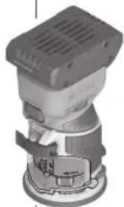
Product features
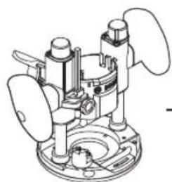
The numbering of the product features refers to the diagram of the power tool on the graphics page.
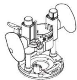
(1) Motor unit
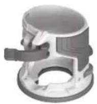
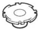
(2) Fixed routing base
(3) Speed preselection thumbwheel
(4) Thumbwheel for fine adjustment of routing depth
(5) Router bit ^4
(6) Cap nut with collet
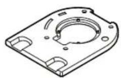
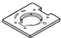
(7) Base plate
(8) Spindle locking lever
(9) Scale for setting the routing depth
(10) Clamping lever
(11) On/off switch
(12) Rechargeable battery
(13) Rechargeable battery release button
(14) Handle (insulated gripping surface)
(15) Collet
(16) Shaft
(17) Open-ended spanner (17 mm) ^a)
(18) Knurled screw for attachments (19), (21), (32), (33)
(19) Parallel guide ^a)
(20) Wing bolt for parallel guide ^a
(21) Flush trim roller guide ^a)
(22) Wing bolt for fixing the horizontal alignment ^a)
(23) Wing bolt for the horizontal alignment of the flush trim roller guide ^a)
(24) Guide roller
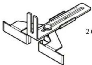
(25) Tilt base ^a1
(26) Wing bolt for angle adjustment ^a)
(27) Scale for routing angle adjustment
(28) Plunge base ^a)
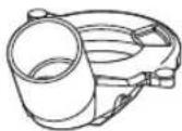
(29) Offset base ^a)
(30) Chip shield for edge routing
(31) Nut for adjustment of the tensioning force
(32) Dust extraction adapter for routing edges ^a)
(33) Dust extraction adapter for routing grooves ^a)
(34) Deluxe routing guide ^a)
(35) Clamping lever (plunge base) ^a)
(36) Release lever for plunge action (plunge base) ^a)
(37) Dust extraction for routing grooves (plunge base) ^4
(38) Dust extraction for routing edges (plunge base) ^a)
(39) Drive wheel (for offset base) ^a)
(40) Opening in the base plate (offset base) ^a)
(41) Spindle lock button (offset base) ^a)
(42) Roller/bush guide (offset base) ^a)
(43) Guide bushing ^a)
(44) Adapter for guide bushing ^a)
(45) Centring pin ^a)
(46) Centring cone ^a)
(47) Rib in fixed routing base
(48) Depth adjustment channel on the motor unit
a) This accessory is not part of the standard scope of delivery.
Technical data
| Edge router GKF 18V-8 | ||
| Article number | 3601 FC2 0.. | |
| Rated voltage V 18 | = | |
| No-load speed ^a) | min ^-1 | 10,000–30,000 |
| Speed preselection ● | ||
| Constant electronic control ● | ||
| Compatible collets mm | inches | 6/8 14" |
| Router cage stroke mm 34 | ||
| Weight ^b) | kg 1.094 | |
| Recommended ambient temperature during charging | °C 0 to +35 | |
| Permitted ambient temperature during operation ^c) and during storage | °C –20 to +50 | |
| Recommended rechargeable batteries | GBA 18V...>4.0 AhProCORE18V... | |
| Recommended battery chargers | GAL 18...GAX 18...GAL 36... | |
A) Measured at 20–25 °C with rechargeable battery ProCORE18V 5.5Ah
B) Depending on battery in use
C) Limited performance at temperatures < 0 °C
Values can vary depending on the product, scope of application and environmental conditions. To find out more, visit www.bosch-professional.com/wac.
Rechargeable battery
Bosch sells some cordless power tools without a rechargeable battery. You can tell whether a rechargeable battery is included with the power tool by looking at the packaging.
Charging the battery
▶ Use only the chargers listed in the technical data. Only these chargers are matched to the lithium-ion battery of your power tool.
Note: Lithium-ion rechargeable batteries are supplied partially charged according to international transport regulations. To ensure full rechargeable battery capacity, fully charge the rechargeable battery before using your tool for the first time.
Inserting the Battery
Push the charged battery into the battery holder until it clicks into place.
Removing the Battery
To remove the rechargeable battery, press the battery release button and pull the battery out. Do not use force to do this.
The rechargeable battery has two locking levels to prevent the battery from falling out if the battery release button is pressed unintentionally. The rechargeable battery is held in place by a spring when fitted in the power tool.
Battery charge indicator
Note: Not all battery types have a battery charge indicator. The green LEDs on the battery charge indicator indicate the state of charge of the battery. For safety reasons, it is only possible to check the state of charge when the power tool is not in operation.
Press the button for the battery charge indicator or to show the state of charge. This is also possible when the battery is removed.
If no LED lights up after pressing the button for the battery charge indicator, then the battery is defective and must be replaced.
Battery model GBA 18V...


LED Capacity
| 3× continuous green light 60-100% |
| 2× continuous green light 30-60% |
| 1× continuous green light 5-30% |
| 1× flashing green light 0-5% |
Battery model ProCORE18V...


LED Capacity
| 5 × continuous green light 80–100 % |
| 4 × continuous green light 60–80 % |
| 3 × continuous green light 40–60 % |
LED Capacity
| 2 × continuous green light 20–40 % |
| 1 × continuous green light 5–20 % |
| 1 × flashing green light 0–5 % |
Recommendations for Optimal Handling of the Battery
Protect the battery against moisture and water.
Only store the battery within a temperature range of -20 to 50 °C. Do not leave the battery in your car in the summer, for example.
Occasionally clean the ventilation slots on the battery using a soft brush that is clean and dry.
A significantly reduced operating time after charging indicates that the battery has deteriorated and must be replaced. Follow the instructions on correct disposal.
Fitting
Before carrying out any work on the power tool (e.g. maintenance, tool change etc.), remove the battery from the power tool. There is risk of injury from unintentionally pressing the on/off switch.
Changing the tool
▶ Wearing protective gloves while fitting and changing router bits is recommended.
Original router bits from the extensive range of Bosch accessories are available from your specialist dealer.
Removing the Fixed Routing Base (see figure A)
Before fitting a router bit, you must first separate the fixed routing base (2) from the motor unit (1).
Open the clamping lever (10) and turn the fixed routing base (2) until the rib (47) in the fixed routing base matches the depth adjustment channel (48) on the motor unit. Pull the motor unit (1) up and out of the fixed routing base (2).
Changing the collet (see figure B)
Depending on the router bit used, you may have to change the cap nut with the collet (6) before fitting the router bit. If the right collet for your router bit is already fitted, please follow the work steps in the following section.
The collet (15) must sit in the cap nut with a small amount of play. The cap nut (6) must be easy to fit. If the cap nut or collet is damaged, replace it immediately.
Push the spindle locking lever (8) to the symbol. If necessary, turn the motor spindle manually until it is locked in place.
Unscrew the cap nut (6) anticlockwise with the open-ended spanner (17).
Push the spindle locking lever (8) to the symbol.
14 | English
If required, clean all the parts you want to fit with a soft brush or by blowing them clean with compressed air before assembling them.
Place the new cap nut on the shaft (16).
Loosely tighten the cap nut.
▶ Do not, under any circumstances, tighten the collet with the tightening nut until a router bit has been fitted. The collet may otherwise become damaged.
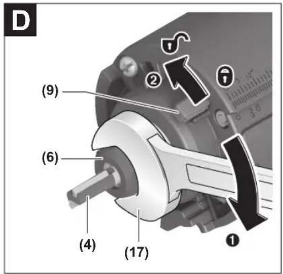
Fitting the router bit (see figures C-D)
▶ Wearing protective gloves while fitting and changing router bits is recommended.
Router bits are available in a wide variety of designs and qualities depending on the intended application.
Router bits made of high-performance high-speed steel (HSS) are suited to machining soft materials such as soft-wood and plastic.
Router bits with carbide tips are especially suitable for hard and abrasive materials such as hardwood and aluminium.
Original router bits from the extensive range of Bosch accessories are available from your specialist dealer. Only use undamaged and clean router bits.
- Push the spindle locking lever (8) to the symbol (1). If required, turn the spindle by hand until the locking mechanism engages. Do not activate the spindle locking lever (8) while the tool spindle is moving.
- Undo the cap nut (6) with the open-ended spanner (17) by turning it anticlockwise (2).
- Slide the router bit into the collet (15). The shank of the router bit must be immersed at least 20 mm into the collet (15).
- Tighten the cap nut (6) with the open-ended spanner (17) by turning it clockwise. Push the spindle locking lever (8) to the symbol.
▶ Do not, under any circumstances, tighten the collet with the tightening nut until a router bit has been fitted. The collet may otherwise become damaged.
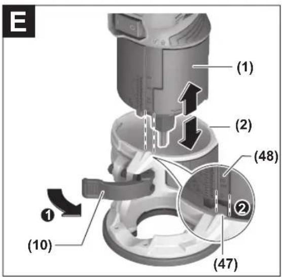
Fitting the Fixed Routing Base (see figures E-F)
To start routing, the fixed routing base (2) must be fitted back onto the motor unit (1).
Open the clamping lever (10) if it is closed.
Align the rib (47) in the fixed routing base (2) with the depth adjustment channel (48) of the motor unit (1).
Slide the motor unit into the fixed routing base until roughly the required cutting depth is reached. Then turn the fixed routing base (2) clockwise as far as it will go in order to activate the fine adjustment mode for the cutting depth.
Use the thumbwheel (4) to precisely set the cutting depth. Close the clamping lever (10).
▶ After assembly, always check that the motor unit is firmly seated in the fixed routing base.
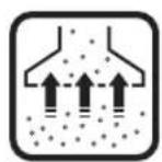
Dust/Chip Extraction
The dust from materials such as lead paint, some types of wood, minerals and metal can be harmful to human health. Touching or breathing in this dust can trigger allergic reactions and/or cause respiratory illnesses in the user or in people in the near vicinity.
Certain dusts, such as oak or beech dust, are classified as carcinogenic, especially in conjunction with wood treatment additives (chromate, wood preservative). Materials containing asbestos may only be machined by specialists.
- Use a dust extraction system that is suitable for the material wherever possible.
- Provide good ventilation at the workplace.
- It is advisable to wear a P2 filter class breathing mask.
The regulations on the material being machined that apply in the country of use must be observed.
- Avoid dust accumulation at the workplace. Dust can easily ignite.
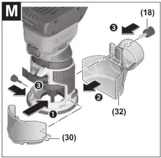
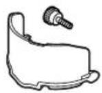
Fitting the Chip Shield for Edge Routing/Dust Extraction Adapter (see figures M-N)
The chip shield for edge routing (30) and dust extraction adapter (32)/(33) can only be used in combination with the round base plate (7) and the optional square and D-shaped base plates (accessories).
Fitting the Chip Shield for Edge Routing (see figure M)
The chip shield for edge routing (30) is particularly suitable for use in combination with the dust extraction adapter for edge routers (32). This ensures maximum dust extraction when routing edges.
Fit the chip shield for edge routing (30) with the supplied screw and click it audibly into the fixed routing base (2).
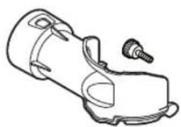
Fitting the dust extraction adapter for edge routing (see figure M)
For routing edges, you can use the dust extraction adapter (32) in addition to the chip shield for edge routing (30).
Attach the dust extraction adapter(32) with the screw (18).
Remove the dust extraction adapter again when routing smooth plane surfaces.
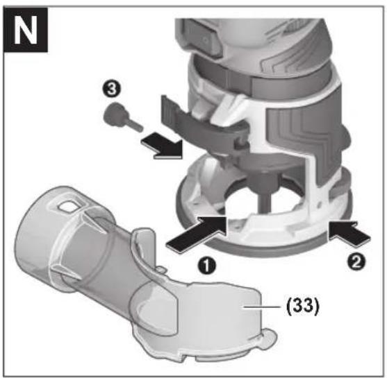
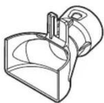
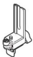
Fitting the dust extraction adapter for groove routing (see figure N)
The dust extraction adapter (33) can be used for routing work on the surface of a workpiece.
Fit the dust extraction adapter (33) with the supplied screw and click it audibly into the fixed routing base (2).
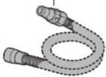
Connecting the Dust Extraction System
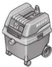
Put an extraction hose (dia. 35 mm) (accessory) on the installed dust extraction adapter. Connect the dust extraction hose to a dust extractor (accessory).
The dust extractor must be suitable for the material being worked.
When extracting dry dust or dust that is especially detrimental to health or carcinogenic, use a special dust extractor.
Operation
Starting Operation
Preselecting the speed
You can preselect the required speed using the speed preselection thumbwheel (3), even during operation.
| Thumbwheel position | Speed [min ^-1 ] |
| 1-2 10,000-14,000 Low speed | |
| 3-4 18,000-24,000 Medium speed | |
| 5-6 26,000-30,000 High speed |
The values displayed in the following table are guidelines. The required speed depends on the material and the working conditions; it can be ascertained through practical tests.
| Material Router bit dia-meter [mm] | Thumbwheel position | |
| Hardwood (beech) 4-10 | 5-6 | |
| 12-20 | 3-4 | |
| >20 | 1-2 | |
| Softwood (pine) 4-10 | 5-6 | |
| 12-20 | 3-6 | |
| >20 | 1-3 | |
| Chipboard 4-10 | 3-6 | |
| 12-20 | 2-4 | |
| >20 | 1-3 | |
| Plastics 4-15 | 2-3 | |
| >15 | 1-2 | |
After working for a long time at a low speed, you should let the power tool rotate at no load for some time at maximum speed to cool down.
Switching on/off
To switch on the power tool, set the on/off switch (11) to 1. To switch off the power tool, set the on/off switch (11) to 0.
Constant electronic control
The Constant Electronic keeps the speed at no load and under load virtually consistent, guaranteeing uniform performance.
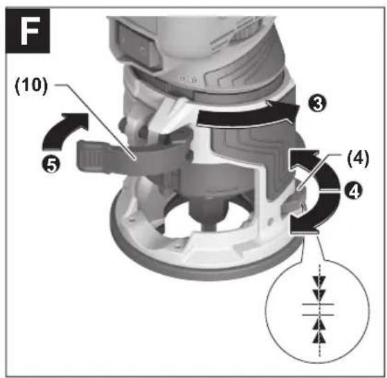
Adjusting the Routing Depth (see figures E-F)
The routing depth must only be set while the power tool is switched off.
For adjustment of the routing depth, proceed as follows:
- Place the power tool with a fitted router bit onto the workpiece you want to machine.
- Open the clamping lever (10) if it is closed (1).
-
Align the rib (47) in the fixed routing base (2) with the depth adjustment channel (48) and the unlocking symbol (2). Slide in the fixed routing base (2) until roughly the required cutting depth is reached.
-
Turn the fixed routing base (2) until the rib (47) matches the locking symbol to make the fine depth adjustment (3).
- Precisely set the required routing depth with the thumbwheel (4) (4).
- Close the clamping lever (10) (5).
Working Advice
▶ Protect router bits against shock and impact.
Edge or profile routing (see figure G)
For edge and profile routing without a parallel guide, the router bit must be fitted with a pilot pin or a ball bearing. While it is switched on, guide the power tool towards the workpiece from the side until the pilot pin or the ball bearing of the router bit is touching the side of the workpiece edge that you want to machine.
Guide the power tool along the workpiece edge. Pay attention that the router is positioned perpendicularly. Too much pressure can damage the edge of the workpiece.
Routing with a parallel guide (see figure H)
You can fit a parallel guide (19) for when cutting parallel to an edge.
Fit the parallel guide (19) to the fixed routing base (2) using the knurled screw (18).
Set the required stop depth using the wing bolt on the parallel guide (20).
While it is switched on, guide the power tool along the workpiece edge with a uniform feed and while applying lateral pressure to the parallel guide.
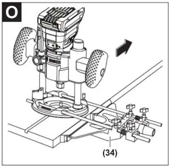
Routing with the deluxe routing guide (see figure O)
With the deluxe routing guide (34), you can move the edge router parallel to a straight edge or create circles and elbows. You can find further information about this in the relevant operating manual.
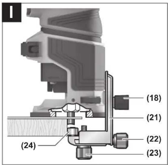
Routing with the Flush Trim Roller Guide (see figure I)
The flush trim roller guide (21) helps when routing edges with router bits without a pilot pin or ball bearing.
Fit the flush trim roller guide to the fixed routing base (2) using the nut (18).
Guide the power tool along the workpiece edge with a uniform feed.
Lateral clearance: To change the amount of material being removed, you can adjust the lateral clearance between the workpiece and the guide roller (24) on the flush trim roller guide (21).
Loosen the wing bolt (22), set the lateral clearance you want by turning the wing bolt (23), then retighten the wing bolt (22).
Height: Set the vertical alignment of the flush trim roller guide according to the router bit you are using and the thickness of the workpiece you want to machine.
Loosen the nut (18) on the flush trim roller guide, slide the flush trim roller guide into the required position and retighten the bolt.
16 | English
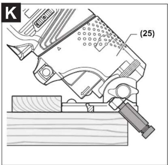
Routing with the Tilt Base (see figures J-L)
The tilt base (25) is particularly suitable for flush routing of laminated edges at hard-to-reach locations, for routing special angles as well as for bevelling edges.
For edge routing using the tilt base, the router bit must be fitted with a pilot pin or a ball bearing.
To fit the tilt base, follow the work steps in the corresponding section (see "Fitting the Fixed Routing Base (see figures E-F)", page 14).
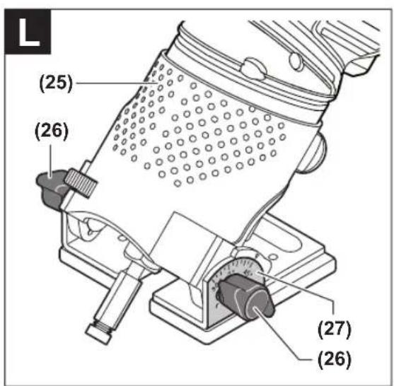
To achieve precise angles, the tilt base (25) is equipped with adjustment notches in increments of 7.5°. The complete adjustment range is 75° (45° towards the front and 30° towards the rear).
Loosen both wing bolts (26).
Set the required angle using the scale (27) and tighten the wing bolts (26) again.
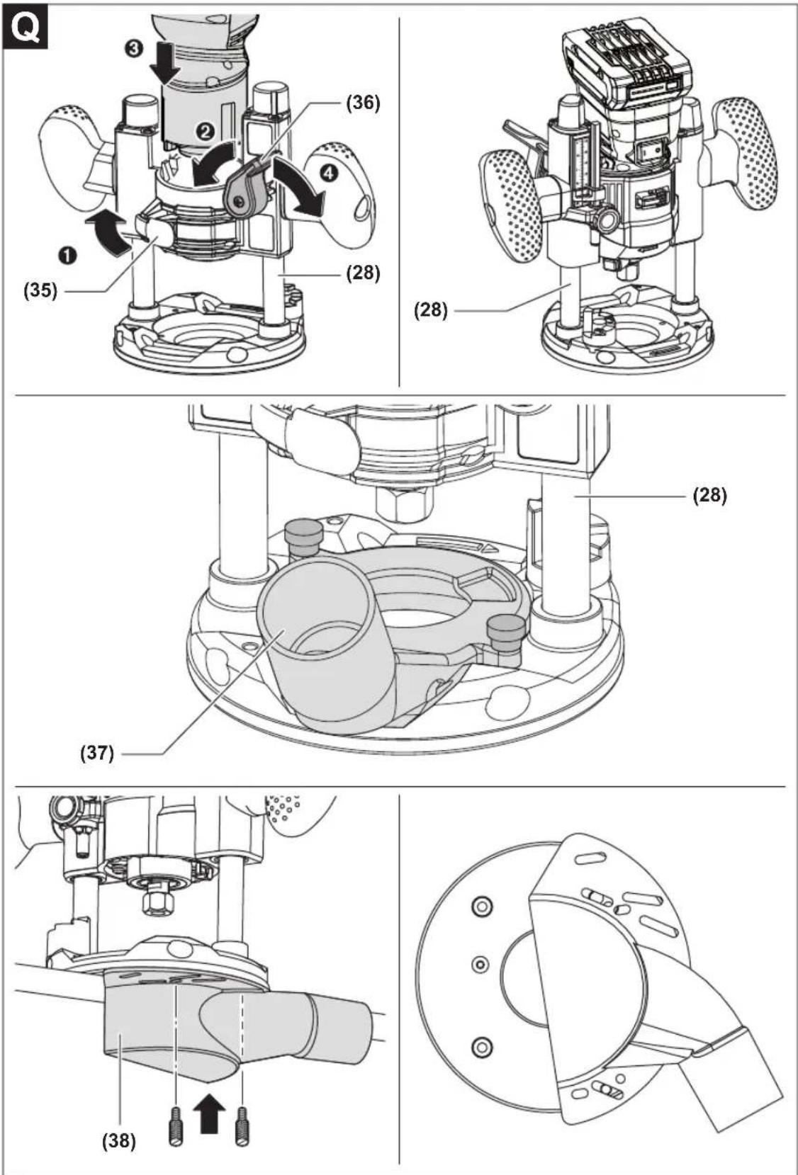
Routing with the plunge base (see figure Q)
With the plunge base (28), you can route grooves, edges, profiles and elongated holes on a stable surface.
Loosen the clamping lever (35) on the plunge base (28). Bring the double arrows on the motor unit (1) and the
plunge base (28) into alignment. Push the motor unit as far as it will go into the plunge base. Turn the motor unit clockwise as far as it will go and close the clamping lever (35).
To lower the motor unit (1), loosen the unlocking lever (36) and press it downwards until you have reached the required depth. Let go of the unlocking lever (36).
Fit the dust extraction for routing grooves (37) or the dust extraction for routing edges (38).
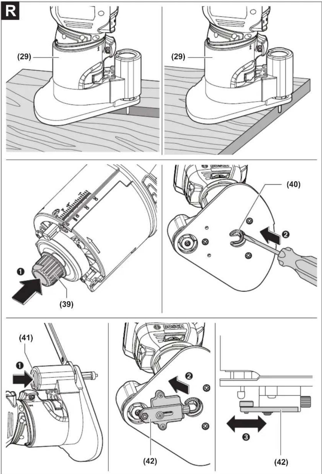
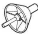
Routing with the Offset Unit (see figure R)
The offset unit can become very hot. Do not use the offset unit for longer than 10 min without break to prevent injuries. Switch the tool off after 10 min and allow it to cool down.
The offset base (29) is intended for routing in tight spaces that are not accessible with the round base plate (7) (e.g. routing near to vertical surfaces).
Remove the collet (15) from the motor unit (1) and fit the drive wheel (39). Insert the motor unit (1) in the offset base (29). Move a screwdriver through the opening (40) in the
base plate of the offset base, in order to place the belt over the drive disc.
Insert the router bit accordingly (see "Fitting the router bit (see figures C-D)", page 14). Press the spindle lock button (41) on the offset base (29) and tighten the cap nut (6).
The roller/bush guide (42) of the offset base (29) is used when you are routing edges with non-mounted application tools. Attach the roller/bush guide (42) with 2 screws. The width of the removed material is determined by the distance set between the front side of the router and the front side of the roller/bush.
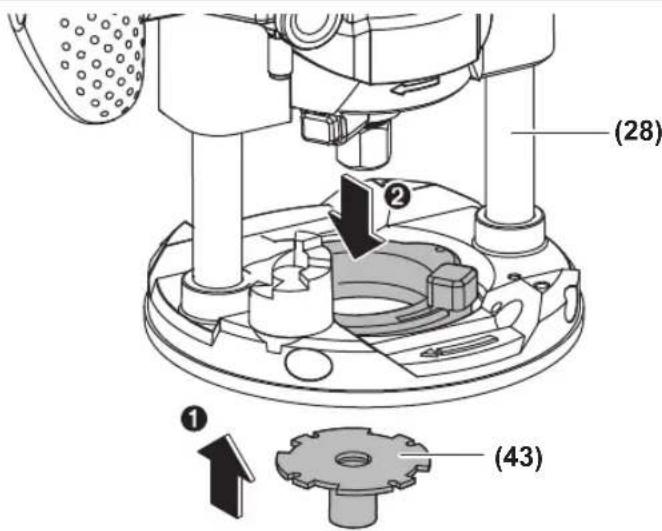
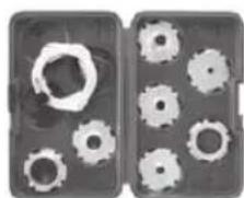
Routing with guide bushing (see figure S)
Using the guide bushing (43), you can transfer contours from templates or patterns to the workpiece.
Select the guide bushing that is suitable for the thickness of the template or pattern. Due to the protruding height of the guide bushing, the template must have a minimum thickness of 8 mm.
When routing with guide bushings, only use router bits that are 2 mm smaller than the internal diameter of the guide bushing.
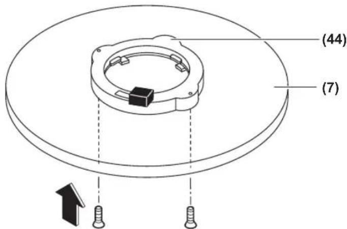
Place the adapter for the guide bushing (44) on the base plate (7). Align the two holes on the underside of the adapter (44) with the drill holes in the base plate (7). Attach the adapter (44) with the supplied screws.
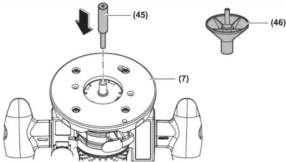
The base plate (7) is centred at the factory. As a result, the router bit is positioned in the middle of the base plate and the guide bushing (43). In order to centre the base plate and the guide bushing as accurately as possible, you can use an optional centring device.
Fit the adapter (44) and the guide bushing (43). Loosen the 4 screws on the base plate (7). Push the centring pin (45) through the base plate into the collet (15) and fasten it with the cap nut (6). Press the centring pin slightly into the base plate or the guide bushing. Retighten the screws on the base plate (7). Remove the centring pin (45).
The centring cone (46) can be used to centre the base plate or wide guide bushings.
Changing the Base Plate
Undo the 4 screws under the base plate (7) and remove it. Fit the new base plate (accessory) in the correct position with the 4 screws.
Troubleshooting
| Problem Cause Remedy | ||
| The router does not work. | Battery not inserted/battery discharged Insert a charged battery. | |
| Temperature of battery and router too high/low Allow the battery and/or router to reach the per- mitted operating temperature. | ||
| Router cannot be switched on. The LED flashes. | Spindle lock button in closed position Switch off the router. Push the spindle lock but- ton out of the closed position. Switch on the router. | |
| Battery inserted when the on/off switch is switched on | Switch off the router. Remove the battery and re- insert it. Switch on the router. | |
Maintenance and Service
Maintenance and Cleaning
▶ Before carrying out any work on the power tool (e.g. maintenance, tool change etc.), remove the battery from the power tool. There is risk of injury from unintentionally pressing the on/off switch.
▶ To ensure safe and efficient operation, always keep the power tool and the ventilation slots clean.
Clean the motor unit, the routing depth fine-adjustment mechanism and the inside of the fixed routing base regularly. To do so, use a clean cloth, a brush, or compressed air (see figure P).
After-Sales Service and Application Service
Malaysia
Tel.: (03) 79663194

You can find our service addresses and links to the repair service and spare parts ordering at www.bosch-pt.com/serviceaddresses
In all correspondence and spare parts orders, please always include the 10-digit article number given on the nameplate of the product.
Disposal
Power tools, rechargeable batteries, accessories and packaging should be sorted for environmental-friendly recycling.
Do not dispose of power tools and batteries/re-chargeable batteries into household waste!
Français
modification of the following forms:
gsdmŋʒɔmʊ gɒŋʃɪmədʒn, bs̄ds̄ɔn ɕs/s̄b lḡnmɒŋmədʒn̄g ʃ̄ns̄3ds. ndm̄jdgɔm oŋŋl̄f̄ns̄gnd̄n̄ əglus̄ədn̄nɛɡ ḡul̄dʒn̄s̄ʃ̄ns̄n̄u ls̄bgm̄dʒn̄s̄ɡrm̄n̄ ɕsls̄ʃ̄ynl̄da.
ஒஷாஷாஷாஷாஷாஷாஷாஷாஷாஷாஷாஷாஷாஷாஷாஷாஷாஷாஷாஷாஷாஷாஷாஷாஷாஷஎ
, , , , )
zsdmlsbygmo 3md3m6g6&gdo
Corruption 6500s 1 3560 LED 5–30 %
BODBODS BOMGDS 1 H36G LED 0-5 %
3m6b0s60y6n 0000000000000
3m6b6b6y6n gngd6m6n6s n6s6h6g6u yjdn luzm0u dmy6n 6m6g6u os g6h6n6n6n4d3d 3m6d6n6y6m6o dy6n6z g6m6g6y os y6h6h6g6ny6m2u dy6sm6n5u ns6s6m 6s6m6gm6s5u.
3g6f0m0g0n 3m6yun (46) 3g70d0ns0n 3s8mn0g6mm 1ssy6cg6n 3gn0n l 3g6f0m0g0n0z0n l 5b 3s6ng6m 3n6g5p0s0g0n 3s6n0n0z0n l.
lsynggbn gnnnln dgh3ms
sāmbṃsbōgān mǎn bānsbōn lùyángōgōn əzņmnl dʒʒʒəwōb (7) ωs sāmāngjān oú. ωssāmdbōgōgōn əbsām lùyángōgōn əzņms (sījūɡyāsnā) ʊʃīm n ʒmδαγμσān mǎn bānsbōn lùgāʒgmān
உரைக்காமாடு வேர்
www.bosch-pt.com/serviceaddresses
ل Effect. Departices Marketing for the Practure of the Practure of the Practure of the Practure of the Practure of the Practure of the Practure of the Practure of the Practure of the Practure of the Practure of the Practure of the Practure of the Practure of the Practure of the Practure of the Practure of the Practure of the Practure of the Practure of the Practure.
natural_image
Technical line drawing of a mechanical device with no visible text or symbols060160A800
2608001112
natural_image
Technical line drawing of a mechanical clamp or holder device (no text or symbols)2 608 000 334
108
2608001110
2608001111
natural_image
Technical line drawing of a mechanical clamp or bracket assembly (no text or symbols)2 608 000 331
2 608 190 065
natural_image
Line drawing of a mechanical component with a cylindrical shaft and flange (no text or symbols)2 608 190 061
natural_image
Technical line drawing of a mechanical component with internal curved surfaces (no text or symbols)2 608 190 062
2 608 000 332
natural_image
Technical line drawing of a mechanical assembly with gears and housing (no text or symbols)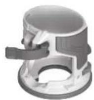
8 mm
12 mm
1/4"
1/2"
2 608 000 498

(Metric)
2 608 190 063
natural_image
Two gray rectangular panels with white gear-like cutouts, no text or symbols visible(Inch)
2 608 190 064
13 mm 2 609 200 138
16 mm 2 609 200 471
17 mm 2 609 200 139
24mm 2609200140
27 mm 2609200141
30 mm 2 609 200 142
40 mm 2 609 200 312
natural_image
Technical line drawing of a mechanical device with no visible text or symbols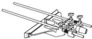
natural_image
Technical line drawing of a mechanical assembly with intersecting rods and pipes (no text or symbols)2607001387
2608000627
2 608 000 488
1 600 A00 1F8 (2x)
2 609 200 145 (0,8 m)
1 600 Z00 005 (800 mm)
1 600 Z00 006 (1100 mm)
1 600 Z00 00F (1600 mm)
1 600 Z00 007 (2100 mm)
1 600 Z00 008 (3100 mm)
1 600 Z00 03V (800 mm)
1 600 Z00 03W (1600 mm)
1 600 Z00 00G
1 600 Z00 03X
1600A0011C
2 607 002 632
GAS 20 L SFC
∅ 38 mm:
1 600 A00 0JF (3 m)
natural_image
3D rendered mechanical component with no visible text or symbols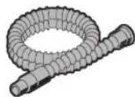
natural_image
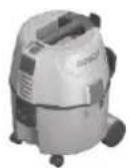
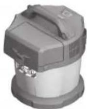
Illustration of a Bosch vacuum cleaner (no text or symbols visible)natural_image
Exterior view of a portable vacuum cleaner with control panel and wheels (no visible text or symbols)GAS 55 M AFC
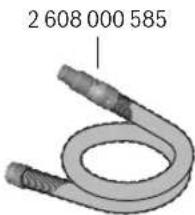
∅ 35 mm: 2 608 000 658 (1,6 m)
natural_image
Close-up of a mechanical device with a metallic handle and internal components (no visible text or symbols)GAS 18V-10 L
Legal Information and Licenses
LEGAL INFORMATION AND LICENSES
BSD-3-Clause ARM CMSIS
Cortex-M Core, v3.2.0
Copyright (c) 2009 - 2013 ARM LIMITED
Redistribution and use in source and binary forms, with or without modification, are permitted provided that the following conditions are met:
- Redistributions of source code must retain the above copyright notice, this list of conditions and the following disclaimer.
- Redistributions in binary form must reproduce the above copyright notice, this list of conditions and the following disclaimer in the documentation and/or other materials provided with the distribution.
- Neither the name of ARM nor the names of its contributors may be used to endorse or promote products derived from this software without specific prior written permission.
THIS SOFTWARE IS PROVIDED BY THE COPYRIGHT HOLDERS AND CONTRIBUTORS AS IS AND ANY EXPRESS OR IMPLIED WARRANTIES, INCLUDING, BUT NOT LIMITED TO, THE IMPLIED WARRANTIES OF MERCHANTABILITY AND FITNESS FOR A PARTICULAR PURPOSE ARE DISCLAIMED. IN NO EVENT SHALL COPYRIGHT HOLDERS AND CONTRIBUTORS BE LIABLE FOR ANY DIRECT, INDIRECT, INCIDENTAL, SPECIAL, EXEMPLARY, OR CONSEQUENTIAL DAMAGES (INCLUDING, BUT NOT LIMITED TO, PROCUREMENT OF SUBSTITUTE GOODS OR SERVICES; LOSS OF USE, DATA, OR PROFITS; OR BUSINESS INTERRUPTION) HOWEVER CAUSED AND ON ANY THEORY OF LIABILITY, WHETHER IN CONTRACT, STRICT LIABILITY, OR TORT (INCLUDING NEGLIGENCE OR OTHERWISE) ARISING IN ANY WAY OUT OF THE USE OF THIS SOFTWARE, EVEN IF ADVISED OF THE POSSIBILITY OF SUCH DAMAGE.
BSD-3-Clause
Infineon TLE987x Series Device Support, v1.5.0
Copyright (c) 2015, Infineon Technologies AG All rights reserved. Redistribution and use in source and binary forms, with or without modification, are permitted provided that the following conditions are met:
- Redistributions of source code must retain the above copyright notice, this list of conditions and the following disclaimer.
- Redistributions in binary form must reproduce the above copyright notice, this list of conditions and the following disclaimer in the documentation and/or other materials provided with the distribution.
- Neither the name of the copyright holders nor the names of its contributors may be used to endorse or promote products derived from this software without specific prior written permission.
THIS SOFTWARE IS PROVIDED BY THE COPYRIGHT HOLDERS AND CONTRIBUTORS "AS IS" AND ANY EXPRESS OR IMPLIED WARRANTIES, INCLUDING, BUT NOT LIMITED TO, THE IMPLIED WARRANTIES OF MERCHANTABILITY AND FITNESS FOR A PARTICULAR PURPOSE ARE DISCLAIMED. IN NO EVENT SHALL THE COPYRIGHT HOLDER OR CONTRIBUTORS BE LIABLE FOR ANY DIRECT, INDIRECT, INCIDENTAL, SPECIAL, EXEMPLARY, OR CONSEQUENTIAL DAMAGES (INCLUDING, BUT NOT LIMITED TO, PROCUREMENT OF SUBSTITUTE GOODS OR SERVICES; LOSS OF USE, DATA, OR PROFITS; OR BUSINESS INTERRUPTION) HOWEVER CAUSED AND ON ANY THEORY OF LIABILITY, WHETHER IN CONTRACT, STRICT LIABILITY, OR TORT (INCLUDING NEGLIGENCE OR OTHERWISE) ARISING IN ANY WAY OUT OF THE USE OF THIS SOFTWARE, EVEN IF ADVISED OF THE POSSIBILITY OF SUCH DAMAGE.
Apache-2.0
ARM CMSIS Cortex-M Core, v5
Copyright 2009-2020 Arm Limited. All rights reserved.
Licensed under the Apache License, Version 2.0
(the "License"); you may not use this file except in compliance with the License.
You may obtain a copy of the License at
http://www.apache.org/licenses/LICENSE-2.0
Unless required by applicable law or agreed to in writing, software distributed under the License is distributed on an "AS IS" BASIS, WITHOUT WARRANTIES OR CONDITIONS OF ANY KIND, either express or implied. See the License for the specific language governing permissions and limitations under the License.
Apache-2.0 CMSIS DSP, v1.8.0
Copyright (C) 2010-2019 ARM Limited or its affiliates. All rights reserved.
Licensed under the Apache License, Version 2.0
(the "License"); you may not use this file except in compliance with the License.
You may obtain a copy of the License at
http://www.apache.org/licenses/LICENSE-2.0
Unless required by applicable law or agreed to in writing, software distributed under the License is distributed on an "AS IS" BASIS, WITHOUT WARRANTIES OR CONDITIONS OF ANY KIND, either express or implied.
See the License for the specific language governing permissions and limitations under the License.
License Text
Apache License
Version 2.0, January 2004
http://www.apache.org/licenses/
TERMS AND CONDITIONS FOR USE, REPRODUCTION, AND
DISTRIBUTION
- Definitions.
"License" shall mean the terms and conditions for use, reproduction, and distribution as defined by Sections 1 through 9 of this document. "Licensor" shall mean the copyright owner or entity authorized by the copyright owner that is granting the License.
"Legal Entity" shall mean the union of the acting entity and all other entities that control, are controlled by, or are under common control with that entity. For the purposes of this definition,
"control" means (i) the power, direct or indirect, to cause the direction or management of such entity, whether by contract or otherwise, or (ii) ownership of fifty percent (50%) or more of the outstanding shares, or (iii) beneficial ownership of such entity.
"You" (or "Your") shall mean an individual or Legal Entity exercising permissions granted by this License.
"Source" form shall mean the preferred form for making modifications, including but not limited to software source code, documentation source, and configuration files.
"Object" form shall mean any form resulting from mechanical transformation or translation of a Source form, including but not limited to compiled object code, generated documentation, and conversions to other media types.
"Work" shall mean the work of authorship, whether in Source or Object form, made available under the License, as indicated by a copyright notice that is included in or attached to the work (an example is provided in the Appendix below).
"Derivative Works" shall mean any work, whether in Source or Object form, that is based on (or derived from) the Work and for which the editorial revisions, annotations, elaborations, or other modifications represent, as a whole, an original work of authorship. For the purposes of this License, Derivative Works shall not include works that remain separable from, or merely link (or bind by name) to the interfaces of, the Work and Derivative Works thereof.
"Contribution" shall mean any work of authorship, including the original version of the Work and any modifications or additions to that Work or Derivative Works thereof, that is intentionally submitted to Licensor for inclusion in the Work by the copyright owner or by an individual or Legal Entity authorized to submit on behalf of the copyright owner. For the purposes of this definition, "submitted" means any form of electronic, verbal, or written communication sent to the Licensor or its representatives, including but not limited to communication on
electronic mailing lists, source code control systems, and issue tracking systems that are managed by, or on behalf of, the Licensor for the purpose of discussing and improving the Work, but excluding communication that is conspicuously marked or otherwise designated in writing by the copyright owner as "Not a Contribution." "Contributor" shall mean Licensor and any individual or Legal Entity on behalf of whom a Contribution has been received by Licensor and subsequently incorporated within the Work.
-
Grant of Copyright License. Subject to the terms and conditions of this License, each Contributor hereby grants to You a perpetual, worldwide, non-exclusive, no-charge, royalty-free, irrevocable copyright license to reproduce, prepare Derivative Works of, publicly display, publicly perform, sublicense, and distribute the Work and such Derivative Works in Source or Object form.
-
Grant of Patent License. Subject to the terms and conditions of this License, each Contributor hereby grants to You a perpetual, worldwide, non-exclusive, no-charge, royalty-free, irrevocable (except as stated in this section) patent license to make, have made, use, offer to sell, sell, import, and otherwise transfer the Work, where such license applies only to those patent claims licensable by such Contributor that are necessarily infringed by their Contribution(s) alone or by combination of their Contribution(s) with the Work to which such Contribution(s) was submitted. If You institute patent litigation against any entity (including a cross-claim or counterclaim in a lawsuit) alleging that the Work or a Contribution incorporated within the Work constitutes direct or contributory patent infringement, then any patent licenses granted to You under this License for that Work shall terminate as of the date such litigation is filed.
-
Redistribution. You may reproduce and distribute copies of the Work or Derivative Works thereof in any medium, with or without modifications, and in Source or Object form, provided that You meet the following conditions:
(a) You must give any other recipients of the Work or Derivative Works a copy of this License; and
(b) You must cause any modified files to carry prominent notices stating that You changed the files; and
(c) You must retain, in the Source form of any Derivative Works that You distribute, all copyright, patent, trademark, and attribution notices from the Source form of the Work, excluding those notices that do not pertain to any part of the Derivative Works; and
(d) If the Work includes a "NOTICE" text file as part of its distribution, then any Derivative Works that You distribute must include a readable copy of the attribution notices contained within such NOTICE file, excluding those notices that do not pertain to any part of the Derivative Works, in at least one of the following places: within a NOTICE text file distributed as part of the Derivative Works; within the Source form or documentation, if provided along with the Derivative Works; or, within a display generated by the Derivative Works, if and wherever such third-party notices normally appear. The contents of the NOTICE file are for informational purposes only and do not modify the License.
You may add Your own attribution notices within Derivative Works that You distribute, alongside or as an addendum to the NOTICE text from the Work, provided that such additional attribution notices cannot be construed as modifying the License. You may add Your own copyright statement to Your modifications and may provide additional or different license terms and conditions for use, reproduction, or distribution of Your modifications, or for any such Derivative Works as a whole, provided Your use, reproduction, and distribution of the Work otherwise complies with the conditions stated in this License.
-
Submission of Contributions. Unless You explicitly state otherwise, any Contribution intentionally submitted for inclusion in the Work by You to the Licensor shall be under the terms and conditions of this License, without any additional terms or conditions. Notwithstanding the above, nothing herein shall supersede or modify the terms of any separate license agreement you may have executed with Licensor regarding such Contributions.
-
Trademarks. This License does not grant permission to use the trade names, trademarks, service marks, or product names of the Licensor, except as required for reasonable and customary use in describing the origin of the Work and reproducing the content of the NOTICE file.
-
Disclaimer of Warranty. Unless required by applicable law or agreed to in writing, Licensor provides the Work (and each Contributor provides its Contributions) on an "AS IS" BASIS, WITHOUT
WARRANTIES OR CONDITIONS OF ANY KIND, either express or implied, including, without limitation, any warranties or conditions of TITLE, NON-INFRINGEMENT, MERCHANTABILITY, or FITNESS FOR A PARTICULAR PURPOSE. You are solely responsible for determining the appropriateness of using or redistributing the Work and assume any risks associated with Your exercise of permissions under this License.
- Limitation of Liability. In no event and under no legal theory, whether in tort (including negligence), contract, or otherwise, unless required by applicable law (such as deliberate and grossly negligent acts) or agreed to in writing, shall any Contributor be liable to You for damages,
including any direct, indirect, special, incidental, or consequential damages of any character arising as a result of this License or out of the use or inability to use the Work (including but not limited to damages for loss of goodwill, work stoppage, computer failure or malfunction, or any and all other commercial damages or losses), even if such Contributor has been advised of the possibility of such damages.
- Accepting Warranty or Additional Liability. While redistributing the Work or Derivative Works thereof, You may choose to offer, and charge a fee for, acceptance of support, warranty, indemnity, or other liability obligations and/or rights consistent with this License. However, in accepting such obligations, You may act only on Your own behalf and on Your sole responsibility, not on behalf of any other Contributor, and only if You agree to indemnify, defend, and hold each Contributor harmless for any liability incurred by, or claims asserted against, such Contributor by reason of your accepting any such warranty or additional liability.
END OF TERMS AND CONDITIONS
WARRANTY DISCLAIMER This product contains Open Source Software components which underlie Open Source Software Licenses. Please note that Open Source Licenses contain disclaimer clauses. The text of the Open Source Licenses that apply are included in this manual under "Legal Information and Licenses".