DIM4 KNX - Smart Home STEINEL - Free user manual and instructions
Find the device manual for free DIM4 KNX STEINEL in PDF.

| Product type | KNX dimming actuator for smart home |
| Width | 72 mm (4 DIN modules) |
| Power supply | 110-230 V~, 50/60 Hz |
| Standby power consumption | Approx. 0.16 W per channel |
| Ambient temperature | -5 to +45 °C |
| KNX connection | TP256, 21-32 V DC, 6-15 mA |
| Compatibility | KNX, ETS from 5.7.3, KNX Data Secure |
| Main functions | Switching and dimming of lamps, Bus/Manual modes, timer, scenes, status feedback, locking, updates via app |
| Mounting | On DIN rail (DIN EN 60715) |
| Safety | Mains disconnection mandatory before intervention, protection against short circuit, overheating, no-load operation |
| Warranty | Legal warranty |
| Maintenance | No special maintenance required |
| Repairability | Interventions reserved for qualified electricians |
Frequently Asked Questions - DIM4 KNX STEINEL
User questions about DIM4 KNX STEINEL
0 question about this device. Answer the ones you know or ask your own.
Ask a new question about this device
Download the instructions for your Smart Home in PDF format for free! Find your manual DIM4 KNX - STEINEL and take your electronic device back in hand. On this page are published all the documents necessary for the use of your device. DIM4 KNX by STEINEL.
USER MANUAL DIM4 KNX STEINEL
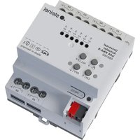
Dimming Actuator DIM4 KNX-S
Art.-Nr. 089191
Inhaltsverzeichnis
Operating instructions
Dimming Actuator DIM4 KNX-S
Art. no. 089191
Table of contents
1 Safety instructions .... 3
2 Device components 3
3 Function.... 4
4 Operation....6
5 Information for electrically skilled persons....9
5.1 Mounting and electrical connection.... 9
5.2 Commissioning 10
6 Technical data 12
7 Troubleshooting.... 13
8 Warranty 16
1 Safety instructions

Electrical devices may be mounted and connected only by electrically skilled persons.
Serious injuries, fire or property damage are possible. Please read and follow the manual fully.
Danger of electric shock. Always disconnect before carrying out work on the device or load. In so doing, take all the circuit breakers into account, which support dangerous voltages to the device and or load.
Danger of electric shock. Device is not suitable for disconnection from supply voltage because mains potential even is applied on the load when the output is switched off. Always disconnect before carrying out work on the device or load. To do so, switch off all associated circuit breakers.
Risk of destruction of the dimmer and load if the set operating mode and load type do not match. Set the correct dimming principle before connecting or exchanging the load.
Fire hazard. For operation with inductive transformers, each transformer must be fused on the primary side in accordance with the manufacturer's instructions. Only safety transformers according to EN 61558-2-6 may be used.
These instructions are an integral part of the product, and must remain with the end customer.
2 Device components
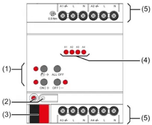
Figure 1: Device components
(1) Button field for manual operation
(2) Programming button and LED
(3) KNX connection
(4) Status LEDs for outputs
(5) Load connections
3 Function
System information
This device is a product of the KNX system and complies with the KNX directives. Detailed technical knowledge obtained in KNX training courses is a prerequisite to proper understanding.
The function of this device depends upon the software. Detailed information on loadable software and attainable functionality as well as the software itself can be obtained from the manufacturer's product database.
The device can be updated. Firmware can be easily updated with the STEINEL KNX Service App (additional software).
The device is KNX Data Secure capable. KNX Data Secure offers protection against manipulation in building automation and can be configured in the ETS project. Detailed technical knowledge is required. A device certificate, which is attached to the device, is required for safe commissioning. During mounting, the device certificate must be removed from the device and stored securely.
Planning, installation and commissioning of the device are carried out with the aid of the ETS, version 5.7.3 and above.
Intended use
- Switching and dimming of incandescent lamps, HV halogen lamps, dimmable HV-LED lamps, dimmable compact fluorescent lamps, dimmable inductive transformers with LV halogen or LV LED lamps, dimmable electronic transformers with LV halogen or LV LED lamps
- Operating in KNX systems
- Mounting on DIN rail according to DIN EN 60715 in sub-distribution unit
If inductive or electronic transformers are connected, observe the data of the transformer manufacturer on loads and the dimming principle.
i HV-LED and compact fluorescent lamps generate high pulsed currents, when they are operated in the leading edge phase control.
Our dimmers take into account the different electronic characteristics of most LED lamps found on the market. However, it cannot be guaranteed that in individual cases the desired results may not be achieved.
Product characteristics
- Outputs can be operated manually, construction site mode
- Feedback in manual mode and in bus mode
-
Disabling of individual outputs manually or by bus
-
Status feedback
- KNX Data Secure compatible
- Updateable with ETS Service App
Dimming operation characteristics
- Automatic or manual selection of the dimming principle suitable for the load
- Protected against no-load, short-circuit and overheating
– Signal in the event of a short-circuit
– Feedback of the switching position and the dimming value - Parameterisable switch-on and dimming behaviour
– Time functions: switch-on delay, switch-off delay, staircase lighting timer with run-on time
– Light scene operation - Status indicator of the outputs via LED
- Operating hours counter
- Mains failure longer than approx. 5 seconds leads to switch-off of the dimming actuator. Depending on the parameter setting, the connected load is calibrated after mains voltage return.
- Increase in output power possible through parallel switching of multiple outputs
– Power extension possible by means of power boosters.
i Delivery state: Construction site mode, outputs can be operated using button field.
Flickering of the connected lamps due to undershoot of the specified minimum load or through centralised pulses from the power stations. This does not represent any defect in the device.
Logic function characteristics
- Logic gate
- Transformer (conversion)
- Disabling element
- Comparator
- Limit value switch
4 Operation
Operating elements
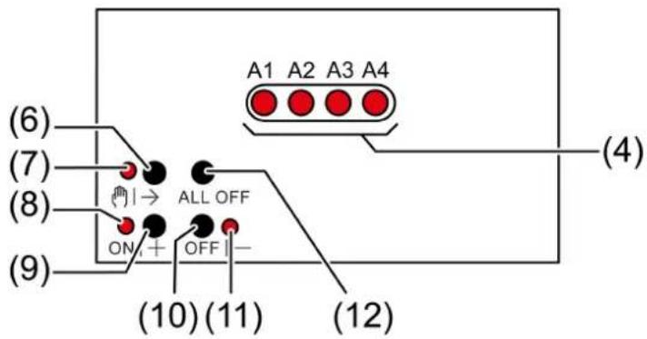
Figure 2: Operating elements
(4) Status LEDs for outputs
-on: output switched on, 1...100%
- flashes at 1 Hz: short-circuit or manual mode
- flashes at 2 Hz: overload, mains voltage failure or firmware update
(6) Button ↗→
- Manual operation
(7) LED 📋|→
-on: continuous manual mode
(8) LED ON|+
-on: selected output on, 1...100%
– flashes: Firmware update
(9) Button ON|+
- Switch on/increase brightness
(10) Button OFF|-
– Switch off/reduce brightness
(11) LED OFF|-
-on: Selected output off
– flashes: Firmware update
(12) Button ALL OFF
- Switching off all outputs
The LEDs (4) optionally indicate the states of the outputs only temporarily (parameter-dependent).
Operating modes
- Bus operation: operation via push-button sensors or other bus devices
- Temporary manual control: manual control locally with keypad, automatic return to bus control
- Continuous manual mode: exclusively manual operation on the device
i No bus operation is possible in manual mode.
i After a bus failure and restoration the device switches to bus operation.
The manual mode can be disabled in ongoing operation via a bus telegram.
Switching on temporary manual operation mode
Operation using the button field is programmed and not disabled.
■ Press button Ⓞ|→ (6) briefly.
LED Ⓞ→ (7) flashes, LED A1... (4) of the first configured output flashes.
Short-time manual operation is switched on.
i After 5 s without a button actuation, the actuator returns automatically to bus operation.
Switching off temporary manual operation mode
The device is in short-term manual mode.
■ No button-press for 5 s.
- or -
■ Press Ⓞ|→ (6) button briefly as many time as necessary until the actuator leaves the short-time manual mode.
Status LED A1... (4) no longer flash, but rather indicate the output status.
Short-time manual operation is switched off.
When switching off the manual control, the outputs, depending on the programming, switch to the active position, e.g. forced position, logic operation.
Switching on permanent manual operation mode
Operation using the button field is programmed and not disabled.
■ Press the ⏻→ (6) button for at least 5 s.
LED Ⓜ→ (7) lights, LED A1... (4) of the first configured output flashes.
Continuous manual mode is switched on.
Switching off permanent manual operation mode
The device is in permanent manual operation mode.
■ Press the ⏻|→ (6) button for at least 5 s.
LED Ⓜ|→ (7) is off.
Continuous manual mode is switched off. Bus operation is switched on.
When switching off the manual control, the outputs, depending on the programming, switch to the active position, e.g. forced position, logic operation.
Switching off all outputs
The device is in permanent manual operation mode.
■ Press the button ALL OFF (7).
All outputs are shut off.
Operating the outputs
The device is in permanent or temporary manual operation mode.
■ Press the button Ⓞ→ (6) briefly as many times as necessary until the desired output is selected.
The LED of the selected output A1... (4) flashes.
The LEDs ON|+ (8) and OFF|- (11) indicate the status.
■ Operate output with ON|+ (9) button or OFF|- (10) button.
Short: switch on/off.
Long: dim brighter/darker.
Release: Stop dimming.
The LEDs ON|+ (8) and OFF|- (11) indicate the status.
i Short-term manual mode: After running through all of the outputs the device exits manual mode after another brief actuation.
Disabling outputs
The device is in permanent manual operation mode. The bus control can be disabled (ETS parameter).
■ Press the button Ⓥ|→ (6) repeatedly until the LED A1... (4) of the desired output flashes.
■ Press the ON|+ (9) and OFF|- (10) buttons simultaneously for approx. 5 s. Selected output is disabled.
The status LED A1... (4) of the selected output flashes quickly.
i A disabled output can be operated in manual mode.
Re-enabling outputs
The device is in permanent manual operation mode. One or more outputs were disabled in manual mode.
■ Press the button Ⓞ|→ (6) repeatedly until the output to be unlocked is selected.
■ Press the ON|+ (9) and OFF|- (10) buttons simultaneously for approx. 5 s. Disabling is deactivated.
LED A1... (4) of the selected output flashes slowly.
5 Information for electrically skilled persons

DANGER!
Mortal danger of electric shock.
Disconnect the device. Cover up live parts.
5.1 Mounting and electrical connection
Mount device
In secure operation (preconditions):
– Secure commissioning is activated in the ETS.
- Device certificate entered/scanned or added to the ETS project. A high resolution camera should be used to scan the QR code.
- Document all passwords and keep them safe.
Observe ambient temperature. Ensure adequate cooling.
■ Maintain a distance of 18 mm, 1 HP when operating multiple dimmers or power units within the same control cabinet.
■ Mount device on DIN rail.
■ In secure operation: The device certificate must be removed from the device and stored securely.
Connect device
■ Connect bus line with KNX device connection terminal observing the correct polarity.
■ Attach the cover cap to the KNX connection as protection against hazardous voltages.

CAUTION!
Danger of destruction. 400 V are shorted when outputs switched in parallel are connected to different outer phase conductors.
The device will be destroyed.
Always connect outputs switched in parallel to the same outer phase conductor.
i Delivery state: The outputs can be operated with manual control.
In the "Universal" operating mode, the dimming actuator only calibrates itself again after disconnection of the load and also after commissioning using the ETS.
i Capacitive-inductive mixed load is not permitted.
For LED leading edge phase control: Connect a maximum of 2 electronic transformers per output.
Connect 600 Watt LED lamps or compact fluorescent lamps at most per 16 ampere circuit breaker. When connecting transformers, observe the data of the transformer manufacturer.
Several dimmer outputs can be combined for dimming greater lamp loads. Only utilise parallel-switched outputs up to 95 % each. Do not connect any compact fluorescent lamps to dimmer outputs switched in parallel.
i Observe delivery state. Before connecting parallel outputs and switching on, program the dimming actuator with ETS to the changed output configuration.
Do not expand parallel-switched dimmer outputs with power packs.
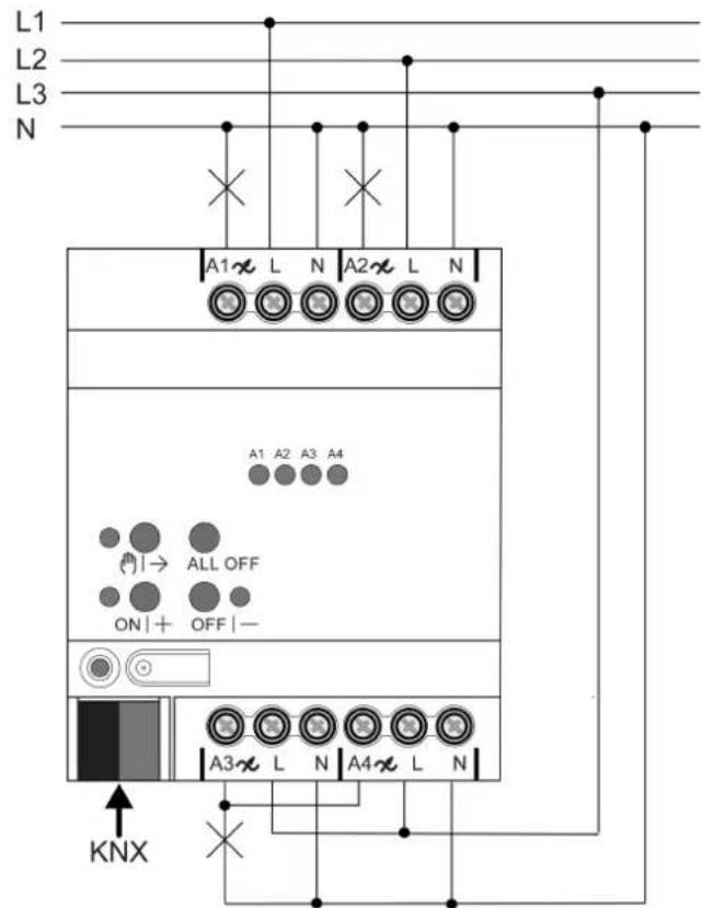
Figure 3: Comfort variant of the device connection with dimmer outputs switched in parallel (connection example)
■ Connect the lamp loads according to the connection example.
5.2 Commissioning
Load physical address and application program
■ Press the programming button.
The programming LED lights up.
■ Load physical address and application program using the ETS.
Safe-state mode
The safe-state mode stops the execution of the loaded application program.
Only the system software of the device is still functional. ETS diagnosis functions and programming of the device are possible. Manual operation is not possible.
Activating safe-state mode
■ Switch off the bus voltage or remove the KNX device connection terminal.
■ Wait about 15 s.
■ Press and hold down the programming button.
■ Switch on the bus voltage or attach the KNX device connection terminal. Release the programming button only after the programming LED starts flashing slowly.
The safe-state mode is activated.
By briefly pressing the programming button again, the programming mode can also be switched on and off in the safe-state mode as usual. If the programming mode is active, the programming LED stops flashing.
Deactivating safe-state mode
■ Switch off bus voltage (wait approx. 15 s) or carry out ETS programming.
Master reset
The master reset restores the basic device settings (physical address 15.15.255, firmware remains in place). The device must then be recommissioned with the ETS. Manual operation is possible.
In secure operation: A master reset deactivates device security. The device can then be recommissioned with the device certificate.
Performing a master reset
Precondition: The safe-state mode is activated.
■ Press and hold down the programming button for > 5 s.
The programming LED flashes quickly.
The device performs a master reset, restarts and is ready for operation again after approx. 5 s.
Restoring the device to factory settings
Devices can be reset to factory settings with the STEINEL KNX Service App. This function uses the firmware contained in the device that was active at the time of delivery (delivered state). Restoring the factory settings causes the devices to lose their physical address and configuration.
6 Technical data
Rated voltage AC 110 ... 230 V \~
Mains frequency 50 / 60 Hz
Power loss max. 7 W
Standby power approx. 0.16 W per channel
Ambient temperature -5 ... +45°C
Storage/transport temperature -25 ... +70°C
Connected load per channel depends on the connected lamps and the set load type: (see figure 4), (see figure 5)
ETS parameter load type
UNI universal (with automatic calibration procedure)
conv. transformer (inductive / leading edge phase control)
LED ♿ LED (leading edge phase control)
electr. transformer (capacitive / trailing edge phase control)
LED △ LED (trailing edge phase control)
| LED | LED | LED | |
| 230V | |||
| W | W | VA | |
| UNI | 1 ... 35 | 20 ... 100 | 20 ... 100 |
| D | - | - | 20 ... 100 |
| LED D | 1 ... 35 | 20 ... 100 | - |
| A | 1 ... 200 | 20 ... 200 | - |
| LED A | 1 ... 200 | 20 ... 200 | - |
| 110V | |||
| W | W | VA | |
| UNI | 1 ... 18 | 20 ... 50 | 20 ... 50 |
| D | - | - | 20 ... 50 |
| LED D | 1 ... 18 | 20 ... 50 | - |
| A | 1 ... 100 | 20 ... 100 | - |
| LED A | 1 ... 100 | 20 ... 100 | - |
Figure 4: LED lamp loads
| 230V | ||||
| W | W | VA | W | |
| UNI | 20 ... 225 | 20 ... 210 | 20 ... 210 | 20 ... 80 |
| D | 20 ... 210 | — | 20 ... 210 | — |
| LED D | 20 ... 210 | 20 ... 210 | — | 20 ... 80 |
| L | 20 ... 225 | 20 ... 225 | — | 20 ... 150 |
| LED L | 20 ... 225 | 20 ... 225 | — | 20 ... 150 |
| 110V | ||||
| W | W | VA | W | |
| UNI | 20 ... 120 | 20 ... 110 | 20 ... 110 | 20 ... 40 |
| D | 20 ... 110 | — | 20 ... 110 | — |
| LED D | 20 ... 110 | 20 ... 110 | — | 20 ... 40 |
| L | 20 ... 120 | 20 ... 120 | — | 20 ... 75 |
| LED L | 20 ... 120 | 20 ... 120 | — | 20 ... 75 |
Figure 5: conventional lamp loads
i Capacitive-inductive mixed load is not permitted.
Connection
Single stranded 0.5 ... 4 mm ^2
Finely stranded without conductor sleeve 0.5 ... 4 mm ^2
Finely stranded with conductor sleeve 0.5 ... 2.5 mm ^2
Connection torque, screw terminals max. 0.8 Nm
Installation width 72 mm / 4 HP
KNX
KNX medium TP256
Commissioning mode S mode
Rated voltage KNX DC 21 ... 32 V SELV
Current consumption KNX 6 ... 15 mA
Connection mode KNX Device connection terminal
7 Troubleshooting
Connected LED lamps or compact fluorescent lamps switch off in the lowest dimming position or flicker
The set minimum brightness is too low.
Increase minimum brightness.
Connected LED lamps or compact fluorescent lamps flicker
Cause 1: Lamps are not dimmable.
Check manufacturer's instructions.
Exchange lamps for another type.
Cause 2: Dimming principle and lamps do not optimally match.
For HV-LED: Check operation in another dimming principle, reduce connected load as well if necessary.
For LV-LED: Check the lamp operating device and replace as necessary.
With the "Universal" setting: Define the dimming principle manually.
Connected HV-LED lamps or compact fluorescent lamps in the lowest dimming position are too bright; dimming range is too small
Cause 1: The set minimum brightness is too high.
Reduce minimum brightness.
Cause 2: HV-LED trailing edge phase control dimming principle does not optimally match the connected lamps.
Check operation in the "HV-LED leading edge phase control" setting, reduce connected load as well if necessary.
Exchange lamps for another type.
Output has switched off.
Cause 1: Overheating protection has tripped.
Disconnect all outputs from the mains, switch-off the corresponding circuit breakers.
HV-LED trailing edge phase control: Reduce the connected load. Exchange lamps for another type.
HV-LED leading edge phase control: Reduce the connected load. Check the operation in the "HV-LED trailing edge phase control" setting. Exchange lamps for another type.
Let device cool down for at least 15 minutes. Check installation situation, ensure cooling, e.g. provide distance from surrounding devices.
Cause 2: Overvoltage protection has tripped.
HV-LED trailing edge phase control: Check the operation in the "HV-LED leading edge phase control" setting, reduce the connected load as well if necessary.
Exchange lamps for another type.
The response of the surge protection can be signalled by sending a short-circuit telegram or can be determined by polling the "short-circuit" communication object.
Cause 3: short-circuit in output circuit
Disconnect all outputs from the mains.
Eliminate short-circuit.
Switch on mains voltage to the outputs again. Switch the affected output off and on again.
When a short-circuit occurs the affected output switches off. Automatic restart when short-circuit is eliminated within 100 ms (inductive load) or 7 seconds (capacitive or ohmic load). After that lasting switch-off.
When a short-circuit occurs during the calibration process, the load calibrates itself again after the short-circuit is eliminated.
Cause 4: load failure.
Check load, replace lamp. For inductive transformers, check primary fuse and replace if necessary.
Manual control with button field not possible
Cause 1: Manual control has not been programmed. Program manual control.
Cause 2: Manual control via bus disabled. Enable manual control.
None of the outputs can be operated
Cause 1: All of the outputs are disabled. Cancel disabling.
Cause 2: Manual mode active. Deactivate manual mode (switch off continuous manual mode).
Cause 3: Application software missing or faulty. Check and correct the programming.
All outputs off and not possible to switch on
Cause 1: bus voltage failure. Check bus voltage.
Luminaires flicker or buzz, proper dimming not possible, device buzzes
Cause: wrong dimming principle set.
Installation or commissioning error. Disconnect device and luminaire, switch off circuit breaker.
Check installation and correct.
If the wrong dimming principle has been preselected: Set correct dimming principle.
If dimming actuator calibrates itself incorrectly, e.g. with highly inductive mains or long load cables: preselect correct dimming principle with commissioning.
LED lamp is dimly lit when dimmer is switched off
Cause: LED lamp is not optimally suited for this dimmer.
Use a compensation module (on request).
Use another type of LED lamp or an LED lamp of another manufacturer.
8 Warranty
We reserve the right to make technical and formal changes to the product in the interest of technical progress.
We provide a warranty as provided for by law.
STEINEL GmbH
Dieselstraße 80-84
33442 Herzebrock-Clarholz
Telefon +49 5245 448 0
www.steinel.de
info@steinel.de
Dimming Actuator DIM4 KNX-S
Núm. de art. 089191
Índice
Figura 1: Estructura del aparato
Dimming Actuator DIM4 KNX-S
Réf. 089191
Sommaire
Court : activation/désactivation.
Activer le mode Safe State
Désactiver le mode Safe State
Dimming Actuator DIM4 KNX-S
N. art. 089191
Indice
Dimming Actuator DIM4 KNX-S
Art. nr. 089191
Inhoudsopgave
Dimming Actuator DIM4 KNX-S
Art.-nr. 089191
Innholdsfortegnelse
Koble inn permanent manuell drift