UA24 KNX - Smart Home STEINEL - Free user manual and instructions
Find the device manual for free UA24 KNX STEINEL in PDF.

| Product type | KNX actuator for blinds and switching |
| Brand | Steinel |
| Model | UA24 KNX |
| Category | Smart home |
| Dimensions (width) | 72 mm (4 modules) / 144 mm (8 modules) / 216 mm (12 modules) depending on reference |
| Weight | Approx. 230 g (4 modules) / 500 g (8 modules) / 740 g (12 modules) |
| Power supply | KNX bus DC 21–32 V SELV, current consumption 5–24 mA depending on reference |
| Switching voltage | AC 250 V ~ |
| Max. switching current | 16 A (AC1), 16 AX (fluorescent lamps) |
| Number of outputs | 4 relay outputs (configurable as 2 blind outputs or 4 switching outputs) |
| Main functions | Switching blinds, roller shutters, awnings; blind mode with slats; NO/NC switching mode; timer functions, scenarios, sun protection, wind/rain/frost alarms; manual control; KNX Data Secure |
| KNX compatibility | KNX TP256, S mode, ETS ≥ 5.7.3 |
| Software update | Via STEINEL KNX Service App |
| Operating temperature | -5 °C to +45 °C |
| Storage temperature | -25 °C to +70 °C |
| Protection rating | IP20 (DIN rail mounting) |
| Mounting | On DIN rail (EN 60715) |
| Connection | Screw terminals, cross-section 0.5–4 mm² (solid) or 0.5–2.5 mm² (stranded with ferrule) |
| Warranty | Legal warranty, manufacturer: STEINEL GmbH, Germany |
Frequently Asked Questions - UA24 KNX STEINEL
User questions about UA24 KNX STEINEL
0 question about this device. Answer the ones you know or ask your own.
Ask a new question about this device
Download the instructions for your Smart Home in PDF format for free! Find your manual UA24 KNX - STEINEL and take your electronic device back in hand. On this page are published all the documents necessary for the use of your device. UA24 KNX by STEINEL.
USER MANUAL UA24 KNX STEINEL
Operating instructions
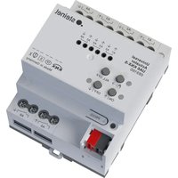
Universal Actuator UA6 KNX-S
Art.no.089160
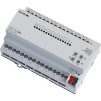
Universal Actuator UA16 KNX-S
Art.no.089177
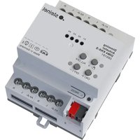
Universal Actuator UA24 KNX-S
Art.no.089184
Table of contents
1 Safety instructions 3
2 Device components 3
3 Function 4
4 Operation 5
5 Information for electrically skilled persons 9
5.1 Mounting and electrical connection 9
5.2 Commissioning 11
6 Technical data 12
7 Warranty 14
1 Safety instructions

Electrical devices may be mounted and connected only by electrically skilled persons.
Serious injuries, fire or property damage are possible. Please read and follow the manual fully.
Danger of electric shock on the SELV/PELV installation. Do not connect loads for mains voltage and SELV/PELV together to the device.
For parallel connection of several motors to an output it is essential to observe the corresponding instructions of the manufacturers, and to use a cut-off relay if necessary. The motors may be destroyed.
Use only venetian blind motors with mechanical or electronic limit switches. Check the limit switches for correct mastering. Observe the specifications of the motor manufacturers. Device can be damaged.
Do not connect any three-phase motors. Device can be damaged.
These instructions are an integral part of the product, and must remain with the end customer.
2 Device components
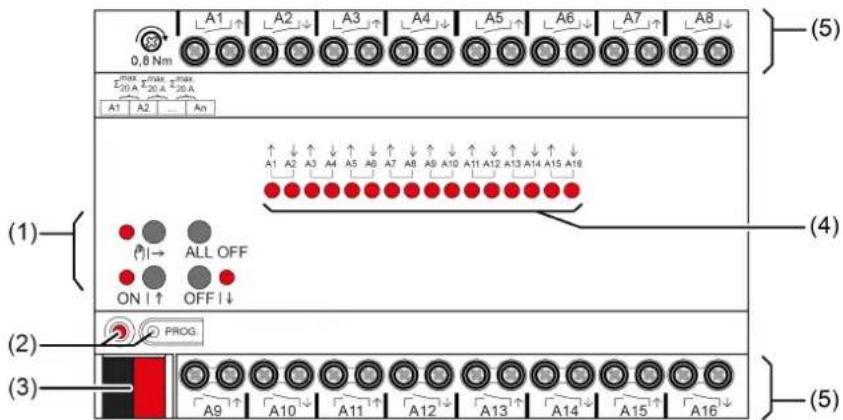
Figure 1: Device components
(1) Button field for manual operation
(2) Programming button and LED
(3) KNX connection
(4) Status LEDs for outputs
(5) Load connections (relay outputs)
3 Function
System information
This device is a product of the KNX system and complies with the KNX directives. Detailed technical knowledge obtained in KNX training courses is a prerequisite to proper understanding.
The function of this device depends upon the software. Detailed information on loadable software and attainable functionality as well as the software itself can be obtained from the manufacturer's product database.
The device can be updated. Firmware can be easily updated with the STEINEL KNX Service App (additional software).
The device is KNX Data Secure capable. KNX Data Secure offers protection against manipulation in building automation and can be configured in the ETS project. Detailed technical knowledge is required. A device certificate, which is attached to the device, is required for safe commissioning. During mounting, the device certificate must be removed from the device and stored securely.
Planning, installation and commissioning of the device are carried out with the aid of the ETS, version 5.7.3 and above.
Intended use
- Switching of electrical loads with potential-free contacts
- Switching of electrically-driven Venetian blinds, roller shutters, awnings and similar hangings
- Installation in sub-distribution unit on DIN rail according to DIN EN 60715
Product characteristics
- Outputs can be operated manually, construction site mode
- Manual switching between Venetian blind operation and switching operation without commissioning
- Feedback in manual mode and in bus mode
- Disabling of individual outputs manually or by bus
- Status feedback (e.g. wind alarm)
- KNX Data Secure capable
- Updateable with STEINEL KNX Service App
Characteristics switch operation
Operation as NO or NC contacts
- Feedback function
- Logic and restraint function
- Central switching functions with collective feedback
- Time functions: switch-on delay, switch-off delay, staircase lighting timer with run-on time
- Scene function
- Operating hours counter
Characteristics Venetian blinds operation
- Suitable for AC motors 110...230 V
- Operating modes "Venetian blind with slats", "Roller shutter/awning", "Venting louvre/roof window"
- Blind/shutter position directly controllable
- Slat position directly controllable
- Feedback of movement status, blind/shutter position and slat position
- Forced position through higher-level controller
- Safety function: 3 independent wind alarms, rain alarm, frost alarm
Sun protection function with heating/cooling operation - Disabling function (lock-out protection)
- Scene function
Logic function characteristics
- Logic gate
- Transformer (conversion)
- Disabling element
-Comparator - Limit value switch
4 Operation
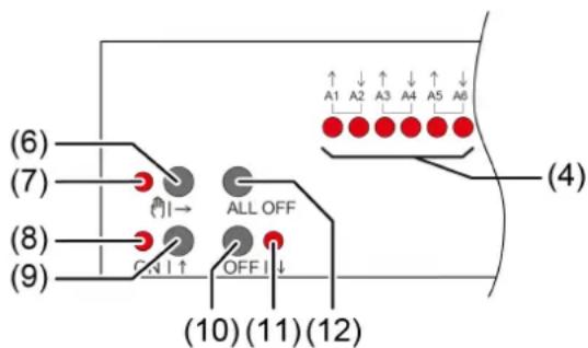
Figure 2: Operating elements
(4) Status LEDs for outputs
ON: Relay output closed
OFF: Relay output opened
Flashes slowly: Output in manual mode selected
Flashes quickly: Output disabled via continuous manual mode
(6) Button Manual operation
(7)LED ON: Continuous manual mode active/Flashing: Temporary manual mode active
(8)LEDON|ON:Relay outputs closed, manual mode active
(9) Button ON|↑
Short: Switch on, adjust slats or stop
Long: Move hanging upwards
(10) Button OFF|↓
Short: Switch off, adjust slats or stop
Long: Move hanging downwards
(11) LED OFF|ON: Relay outputs opened, manual mode active
(12) Button ALL OFF Open all relay outputs, stop drives
In operation with the button field the device distinguishes between a short and a long press.
- Short: Pressing for less than 1 s
- Long: Pressing for between 1 and 5 s
In switching operation, the device distinguishes between the "NO contact" and "NC contact" operating modes. The buttons (9 + 10) switch the switching state when actuated: NO contact: Switch on = close relay, Switch off = open relay NC contact: Switch on = open relay, Switch off = close relay The LED (4 + 8 + 11) always indicate the relay state.
The LEDs (4) optionally indicate the states of the outputs only temporarily (parameter-dependent).
Operating modes
- Bus operation: operation via push-button sensors or other bus devices
- Temporary manual control: manual control locally with keypad, automatic return to bus control
- Continuous manual mode: exclusively manual operation on the device
i No bus operation is possible in manual mode.
i After a bus failure and restoration the device switches to bus operation.
The manual mode can be disabled in ongoing operation via a bus telegram.
Switching on temporary manual operation mode
Operation is not disabled.
Press button (6) briefly.
LED | (7) flashes, LEDs A1... (4) of the first configured output or output pair flash.
Short-time manual operation is switched on.
i After 5 s without a button actuation, the actuator returns automatically to bus operation.
Switching off temporary manual operation mode
The device is in short-term manual mode.
No button-press for 5 s.
-or-
- Press | (6) button briefly as many time as necessary until the actuator leaves the short-time manual mode.
Status LEDs A1... (4) no longer flash, but rather indicate the relay status.
Short-time manual operation is switched off.
Switching outputs: depending on the programming, the output relays switch to the position that is active after the manual mode is switched off, e.g. logic function.
Venetian blind outputs: depending on the programming, the blind moves to the position that is active after the manual mode is switched off, e.g. to safety or sun protection position.
Switching on permanent manual operation mode
Operation is not disabled.
Press the | (6) button for at least 5 s.
LED | (7) lights up, LEDs A1... (4) of the first configured output or output pair flash.
Continuous manual mode is switched on.
Switching off permanent manual operation mode
The device is in permanent manual operation mode.
Press the | (6) button for at least 5 s.
LED (则) (7) is off.
Continuous manual mode is switched off. Bus operation is switched on.
Switching outputs: depending on the programming, the output relays switch to the position that is active after the manual mode is switched off, e.g. logic function.
Venetian blind outputs: depending on the programming, the blind moves to the position that is active after the manual mode is switched off, e.g. to safety or sun protection position.
Operating an output in manual mode
Activate short-term or permanent manual operation.
- Press button | (6) repeatedly until LED A1... (4) of the desired output or output pair flashes.
- Press button ON|↑ (9) or OFF|↓ (10).
- Short: Switch on/off, drive stop.
- Long: Move blind/shutter upwards/downwards.
LED ON|↑ (8) ON: Relay output closed
LED OFF|↓ (7) OFF: Relay output opened
i Short-term manual mode: After running through all of the outputs the device exits manual mode after another brief actuation.
Switching off all outputs / Stopping all hangings
The device is in permanent manual operation mode.
Press the ALL OFF button (12).
Switching outputs: all outputs switch off (NO operating mode: relay output opened/NC operating mode: relay output closed).
Venetian blind outputs: all blinds/shutters stop.
Disabling outputs
The device is in permanent manual operation mode. The bus control can be disabled (ETS parameter).
- Press button | (6) repeatedly until LED A1... (4) of the desired output or output pair flashes.
- Press the ON|↑ (9) and OFF|↓ (10) buttons simultaneously for approx. 5 s. Selected output is disabled.
The status LED A1... (4) of the selected output or output pair flashes quickly.
A disabled output can be operated in manual mode.
Re-enabling outputs
The device is in permanent manual operation mode. One or more outputs were disabled in manual mode.
- Press button | (6) repeatedly until the output to be unlocked or the output pair is selected.
- Press the ON|↑ (9) and OFF|↓ (10) buttons simultaneously for approx. 5 s.
Disabling is deactivated.
The LED A1... (4) of the selected output or output pair flashes slowly.
Switching between Venetian blind and switching operation
Device is not in operation
Activate permanent manual operation.
- Press button | (1) repeatedly until LED A1... (8) of the desired output or output pair flashes.
- Press the (1) and ON (4) and OFF (5) buttons simultaneously for approx. 5 s.
Switching operation: Both status LEDs A1... (8) of the output pair light up.
Venetian blind operation: Both status LEDs A1... (8) of the output pair flash alternately.
- Press the ON|↑ (4) and OFF|↓ (5) buttons simultaneously.
Outputs switch between switching operation and Venetian blind operation.
Both status LEDs A1... (8) indicate the current operating mode.
Press the (1) and ON (4) and OFF (5) buttons simultaneously for approx. 5 s.
Operating mode switchover is terminated, permanent manual operation mode is activated.
Press the button (1) for approx. 5 s.
Operating mode switchover is terminated, permanent manual operation mode is deactivated.
5 Information for electrically skilled persons

DANGER!
Mortal danger of electric shock.
Disconnect the device. Cover up live parts.
5.1 Mounting and electrical connection
Mount device
In secure operation (preconditions):
- Secure commissioning is activated in the ETS.
-
Device certificate entered/scanned or added to the ETS project. A high resolution camera should be used to scan the QR code.
-
Document all passwords and keep them safe.
Observe ambient temperature. Ensure adequate cooling.
Mount device on DIN rail.
- In secure operation: The device certificate must be removed from the device and stored securely.
Connect device
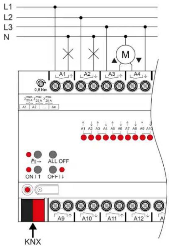
Figure 3: Device connection (connection example)
- Connect bus line with KNX device connection terminal observing the correct polarity.
- Attach the cover cap to the KNX connection as protection against hazardous voltages.
- Connect load as shown in the connection example. Two adjacent relay outputs form a Venetian blind output.
The total current capacity of neighbouring outputs is a maximum of 20 A.
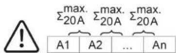
Figure 4: Total current capacity of neighbouring outputs
5.2 Commissioning
Commissioning the device

NOTICE!
Incorrect load control due to undefined relay state at delivery.
Risk of destruction of connected drive motors.
During commissioning, before switching on the load, ensure that all relay contacts are open by applying the KNX bus voltage. Observe commissioning sequence!
- Switch on the KNX bus voltage.
Wait about 10 s.
Switch on load circuits.
i Delivery state: The outputs can be operated with manual control. Outputs are set as Venetian blind outputs.
Load physical address and application program
■ For switched loads, configure the outputs as a switching output.
■ For Venetian blind operation, configure the outputs as a Venetian blind output.
In Venetian blind operation: measure blind/shutter and slat travel times and enter them in the parameter setting.
Press the programming button.
The programming LED lights up.
- Load physical address and application program using the ETS.
Safe-state mode
The safe-state mode stops the execution of the loaded application program.
1 Only the system software of the device is still functional. ETS diagnosis functions and programming of the device are possible. Manual operation is not possible.
Activating safe-state mode
- Switch off the bus voltage or remove the KNX device connection terminal.
Wait about 15 s.
Press and hold down the programming button. - Switch on the bus voltage or attach the KNX device connection terminal. Release the programming button only after the programming LED starts flashing slowly.
The safe-state mode is activated.
By briefly pressing the programming button again, the programming mode can also be switched on and off in the safe-state mode as usual. If the programming mode is active, the programming LED stops flashing.
Deactivating safe-state mode
- Switch off bus voltage (wait approx. 15 s) or carry out ETS programming.
Master reset
The master reset restores the basic device settings (physical address 15.15.255, firmware remains in place). The device must then be recommissioned with the ETS. Manual operation is possible.
In secure operation: A master reset deactivates device security. The device can then be recommissioned with the device certificate.
Performing a master reset
Precondition: The safe-state mode is activated.
- Press and hold down the programming button for >5 s.
The programming LED flashes quickly.
The device performs a master reset, restarts and is ready for operation again after approx. 5 s.
Restoring the device to factory settings
Devices can be reset to factory settings with the STEINEL KNX Service App. This function uses the firmware contained in the device that was active at the time of delivery (delivered state). Restoring the factory settings causes the devices to lose their physical address and configuration.
6 Technical data
KNX
KNX medium TP256
Commissioning mode S mode
Rated voltage KNX DC 21 ... 32 V SELV
Current consumption KNX
Order no. 089160, 089177 5 ... 18 mA
Order no. 089184 5 ... 24 mA
Outputs
Switching voltage AC 250 V ~
Switching current AC1 16 A
Fluorescent lamps 16 AX
Current carrying capacity
Neighbouring outputs 20A
Loads per output
Ohmic load 3000 W
Capacitive load max. 16 A (140 F)
Motors 1380 VA
Switch-on current 200~ s max. 800 A
Switch-on current 20 ms max. 165 A
Lamp loads
Incandescent lamps 2300 W
HV halogen lamps 2300 W
HV-LED lamps max. 400 W
LV halogen lamps with electronic
transformers
LV halogen lamps with inductive
transformer
Compact fluorescent lamps
uncompensated 1000 W
parallel compensated 1160 W (140 F)
Installation width
Order no. 089160 72 mm / 4 HP
Order no. 089177 144 mm / 8 HP
Order no. 089184 216 mm / 12 HP
Weight
Order no. 089160 approx. 230g
Order no. 089177 approx. 500g
Order no. 089184 approx. 740 g
Clampable conductor cross-section
Single stranded 0.5 ... 4 mm²
Finely stranded without conductor sleeve 0.5 ... 4 mm²
Finely stranded with conductor sleeve
Ambient conditions
Ambient temperature
Storage/transport temperature
Connection torque, screw terminals
1500W
1200 VA
0.5 ... 2.5 mm²
-5…+45°C
-25 ... +70°C
max. 0.8Nm
7 Warranty
We reserve the right to make technical and formal changes to the product in the interest of technical progress.
We provide a warranty as provided for by law.
STEINEL GmbH
Dieselstraße 80-84
33442 Herzebrock-Clarholz
Telefon +49 5245 448 0
www.steinel.de
info@steinel.de
Désactiver le mode Safe State
N.ord.089160 ca.230g
N.ord.089177 ca.500g
N.ord.089184 ca.740g
Koble inn permanent manuell drift
Utfore Master-omstart
Forutsetting: Safe-State-modus er aktivert.
Trykk pa programmeringstasten, og hold den >5 s.
Programmerings-LED-en blinker raskt.
Hoyvoltshalogenlamper 2300 W
HV-LED-lamper maks. 400 W