D21585 - Drill DEWALT - Free user manual and instructions
Find the device manual for free D21585 DEWALT in PDF.


User questions about D21585 DEWALT
0 question about this device. Answer the ones you know or ask your own.
Ask a new question about this device
Download the instructions for your Drill in PDF format for free! Find your manual D21585 - DEWALT and take your electronic device back in hand. On this page are published all the documents necessary for the use of your device. D21585 by DEWALT.
USER MANUAL D21585 DEWALT
English (original instructions) 23
natural_image
Line drawing of a handheld electrical plug with a terminal labeled 'R' and a secondary plug (no text or symbols beyond label)Figure 2
text_image
Technical diagram of a vacuum cleaner assembly with labeled parts including pump, fan, and base standFigure 3
natural_image
Technical line drawing of a drill press and clamp assembly (no text or symbols)Figure 4
text_image
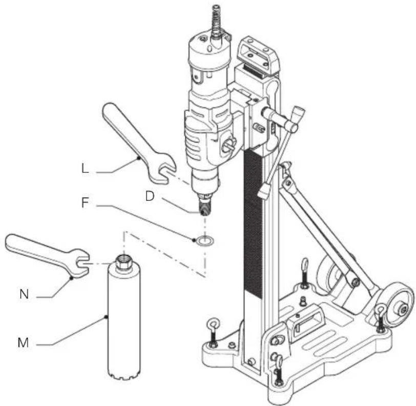
Technical diagram of a mechanical drill press with labeled parts including drill bit, wrench, and baseFigure 5
text_image
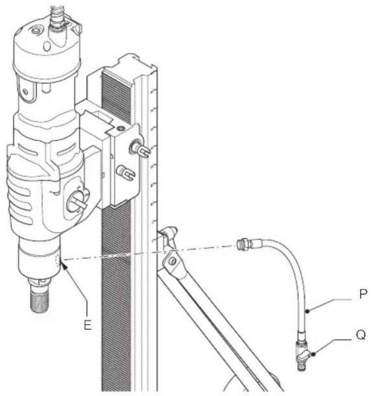
Technical diagram of a mechanical device with labeled parts E, P, and Q, showing assembly or assembly details.Figure 6
text_image
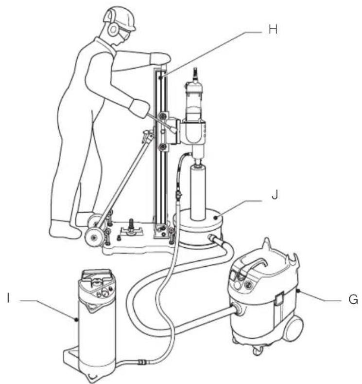
Technical diagram of a mechanical device with labeled components I, J, H, and GDIAMANTBOREMASKINE D21585
Tillykke!
VALGFRIT TILBEH∅R (FIG. 2)
F. D215854 Sæt kobberinge (5 stk.)
G. D27902 Støvopsamler
H. D215851 Borestander
I. D215824 Vandpumpe
J. D215852
Vandsamlingsring
(til brug samme med D215851)
K. D215853
Ekstra pakning til vandsamlingsring
(3 stk.)
(til brug samme med D215852)
TILSIGTET BRUG
I = ON (rød LED lyser op).
- Reducer vandstrømmen.
Forkert rotationshastighed
You have chosen a DEWALTtool. Years of experience, thorough product development and innovation make DEWALT one of the most reliable partners for professional power tool users.
Technical Data
| D21585 | ||
| Voltage(V.K. & Ireland only) V 230/115 | 230 | |
| Type 1 | ||
| Power input W 2,500/2,220 | ||
| Power output W 1,500/1,350 | ||
| No-load speed | ||
| 1st gear min | -1 | 0–500 |
| 2nd gear min | -1 | 0–1,200 |
| 3rd gear min | -1 | 0–2,000 |
| Load speed | ||
| 1st gear min | -1 | 0–290 |
| 2nd gear min | -1 | 0–760 |
| 3rd gear min | -1 | 0–1,280 |
| Spindle thread 1 1/4" (Male) | ||
| Protection class | I | |
| Max. water pressure | bar | 3 |
| Weight | kg | 11.2 |
DRILLING CAPACITIES
| Drilling range in masonry | ||
| 1st gear | mm | 52-300 |
| 2nd gear mm | 52-300 | |
| 3rd gear | mm | 52-250 |
| maximum length | mm | 400 |
Drilling range in concrete
| 1st gear | mm | 52-250 |
| 2nd gear mm | 52-200 | |
| 3rd gear | mm | 52-150 |
| maximum length | mm | 400 |
Noise values and vibration values (triax vector sum) according to EN61029-1:
| L_PA (emission sound pressure level) | dB(A) | 84.3 |
| L_WA (sound power level) | dB(A) | 97.2 |
| K (uncertainty for the given sound level) | dB(A) | 3 |
| Vibration emission value a_n= | m/s2 | 2.4 |
| Uncertainty K = | m/s2 | 2.1 |
The vibration emission level given in this information sheet has been measured in accordance with a standardised test given in EN61029 and may be used to compare one tool with another. It may be used for a preliminary assessment of exposure.

WARNING: The declared vibration emission level represents the main applications of the tool. However if the tool is used for different applications, with different accessories or poorly maintained, the vibration emission may differ. This may significantly increase the exposure level over the total working period.
An estimation of the level of exposure to vibration should also take into account the times when the tool is switched off or when it is running but not actually doing the job. This may significantly reduce the exposure level over the total working period.
Identify additional safety measures to protect the operator from the effects of vibration such as: maintain the tool and the accessories, keep the hands warm, organisation of work patterns.
Fuses:
| Europe | 230 V tools | 10 Amperes, mains |
| U.K. & Ireland | 230 V tools | 13 Amperes, in plugs |
NOTE: This device is intended for the connection to a power supply system with maximum permissible system impedance Zmax of 0.28Ω at the interface point (power service box) of user's supply.
The user has to ensure that this device is connected only to a power system which fulfils the requirement above. If necessary, the user can ask the public power supply company for the system impedance at the interface point.
Definitions: Safety Guidelines
The definitions below describe the level of severity for each signal word. Please read the manual and pay attention to these symbols.

DANGER: Indicates an imminently hazardous situation which, if not avoided, will result in death or serious injury.

WARNING: Indicates a potentially hazardous situation which, if not avoided, could result in death or serious injury.

CAUTION: Indicates a potentially hazardous situation which, if not avoided, may result in minor or moderate injury.
NOTICE: Indicates a practice not related to personal injury which, if not avoided, may result in property damage.
Denotes risk of electric shock.
Denotes risk of fire.
EC-Declaration of Conformity MACHINERY DIRECTIVE

DIAMOND DRILLING MACHINE D21585
DEWALT declares that these products described under Technical Data are in compliance with: 2006/42/EC, EN61029-1:2009 +A11:2010
These products also comply with Directive 2014/30/EU and 2011/65/EU. For more information, please contact DEWALT at the following address or refer to the back of the manual.
The undersigned is responsible for compilation of the technical file and makes this declaration on behalf of DEWALT.
text_image
Mr. RergelMarkus Rompel
Director Engineering
D-65510, Idstein, Germany
20.04.16

IG: To reduce the risk of injury, read the instruction manual.
Safety Instructions

NG! When using electric tools basic safety precautions should always be followed to reduce the risk of fire, electric shock and personal injury including the following.
Read all these instructions before attempting to operate this product and save these instructions.
SAVE THIS MANUAL FOR FUTURE REFERENCE
General Safety Rules
- Keep work area clear.
Cluttered areas and benches invite injuries.
- Consider work area environment.
Do not expose the tool to rain. Do not use the tool in damp or wet conditions. Keep the work area well lit. Do not use the tool in the presence of flammable liquids and gases.
- Guard against electric shock.
Avoid body contact with earthed or grounded surfaces (e.g., pipes, radiators, ranges and refrigerators).
- Keep other persons away.
Do not let persons, especially children, not involved in the work, touch the tool or the extension cord and keep them away from the work area.
- Store idle tools.
When not in use, tools must be stored in a dry place and locked up securely, out of reach of children.
- Do not force the tool.
It will do the job better and safer at the rate for which it was intended.
- Use the right tool.
Do not force small tools to do the job of a heavy duty tool. Do not use tools for purposes not intended; for example do not use circular saws to cut tree limbs or logs.
- Dress properly.
Do not wear loose clothing or jewellery, as these can be caught in moving parts. Non-skid footwear is recommended when working outdoors. Wear protective hair covering to contain long hair.
- Use protective equipment.
Always use safety glasses. Use a face or dust mask if working operations create dust.
10. Connect dust extraction equipment.
If the tool is provided for the connection of dust extraction and collecting equipment, ensure these are connected and properly used.
11. Do not abuse the cord.
Never yank the cord to disconnect it from the socket. Keep the cord away from heat, oil and sharp edges.
12. Secure work.
Where possible use clamps or a vice to hold the work. It is safer than using your hand.
13. Do not overreach.
Keep proper footing and balance at all times.
14. Maintain tools with care.
Keep cutting tools sharp and clean for better and safer performance. Follow instructions for lubricating and changing accessories. Inspect tools periodically and if damaged have them repaired by an authorized service facility. Inspect extension cords periodically and replace if damaged. Keep handles dry, clean and free from oil and grease.
15. Disconnect tools.
When not in use, before servicing and when changing accessories such as blades, bits and cutters, disconnect tools from the power supply.
16. Remove adjusting keys and wrenches.
Form the habit of checking to see that adjusting wrenches are removed from the tool before turning it on.
17. Avoid unintentional starting.
Insure switch is in the "off" position before plugging in.
18. Use outdoor extension leads.
When the tool is used outdoors, use only extension cords intended for outdoor use and marked accordingly.
19. Stay alert.
Watch what you are doing. Use common sense and do not operate the tool when you are tired.
20. Check for damaged parts.
Before furture use of tool, it should be carefully check to determine that it will operate properly and perform its intended function. Check for alignment of moving parts, binding of moving parts, breakage of parts, mounting and any other conditions that may affect its operation. A guard or other part that is damaged should be properly repaired or replaced by an authorized service centre unless otherwise indicated in this
instruction manual. Have defective switches replaced by an authorized service centre. Do not use the tool if the switch does not turn it on and off.

G!The use of any accessory or attachment other than one recommended in this instruction manual may present a risk of personal injury.
21. Have your tool repaired by a qualified person.
This electric tool complies relevant safety rules. Repairs should only be carried out by qualified persons using original spare parts; otherwise this may result in considerable danger to the user.
Additional Specific Safety Rules for Diamond Drills
- Bits, tools and drilling area get hot during operation. Wear gloves when touching them.
- Use the diamond drill under constant supervision.
- Make sure not to cut through electric mains, gas or water pipes. Use detection systems prior to drilling.
- Make sure the cutting accessory is fitted properly.
- Check all screws and tighten securely before you use the machine.
- When drilling downward, make sure the core can drop safely without injuring someone standing beneath.
- Make sure to stand on a stable surface and keep body balance at all times for better control of reaction torque.
- Inspect the machine before every use. Do not use the machine if there are any defectives on the mains plug, power cord, trigger switch or any part of the housing. Have the machine repaired by an authorized repair agent.
- Do not use the machine in a damp or wet location.
- Switch off the machine immediately if there is any leak of water.
- After interrupting the cut, do not switch on until the core bit can rotate freely.
- Always switch the tool off to prevent the machine from accidentally self starting. Note this procedure especially after the power supply is interrupted or the plug is disconnected from the power outlet.
- In case of jammed core bit disconnect the machine from the power supply, remove the reason for the jam before turning on the machine again.
Additional Safety Instructions for water supplied Drills
- Before use check the drill core bits. Never use damaged or deformed core bits.
- Use only drill core bits which are designed and recommended for this machine. Always consider the minimum and maximum diameter and the length given in the technical data.
- Always use hearing protection to reduce the risk of induced hearing loss.
- Wear safety goggles or other eye protection. Drilling operations cause chips to fly. Flying particles can cause permanent eye damage.
- Wear gloves when handling core bits or rough material to reduce injuries by sharp edges.
- Use non-slipping footwear to prevent injuries by slippery surfaces.
- Drilling with stand is only allowed downwards or horizontal. The stand shall be fixed, either by bolts (e.g. D215825) or vacuum fixation.
- Check the surface where the drill stand shall be fixed. Rough surface can significantly reduce the effectiveness of the suction system. Coated or laminated surface can be pulled off during work.
- Control the minimum vacuum level before and during drilling operation when using vacuum pump. The minimum level shall not be less 650 mbar.
- For safe operation and vacuum fixation the diameter of the drill core bit shall not be greater than 82 mm.
WET DRILLING
• Always use a water cooling device and a water collection system.
• Always use core bits designed for wet drilling.
- The maximum water pressure is 3 bar. Use a pressure relieve valve in case of a higher water pressure.
- Use only pure tap water for cooling purposes.
- Prevent water from entering the motor or other electrical components. Make sure the PRCD is not in contact with water.

WARNING: We recommend the use of a residual current device with a residual current rating of 30mA or less.
Residual Risks
In spite of the application of the relevant safety regulations and the implementation of safety devices, certain residual risks cannot be avoided.
These are:
- Impairment of hearing
– Risk of personal injury due flying particles. - Risk of burns due to accessories becoming hot during operation.
– Risk of personal injury due to prolonged use.
The following factors increase the risk of breathing problems:
- No dust extractor connected when performing dry operation
- Insufficient dust extraction caused by uncleand exhaust filters
Markings on Tool
The following pictograms are shown on the tool:

Safe use warning

Read instruction manual before use.

Wear ear protection.

Wear eye protection.

Always wear a dust mask

Always wear safety shoes

Always wear safety gloves.

Water supply

Gear selection
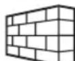
Applications in masonry

Applications in concrete
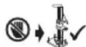
When using the machine, make sure that the machine is mounted on a stand. Never use the machine handheld, as it will lead to loss of control and serious injury.
DATE CODE POSITION
The Date Code which also includes the year of manufacture, is printed into the motor housing.
Example:
2016 XX XX
Year of Manufacture
Package Contents
The package contains:
1 Diamond drilling machine
1 Open ended spanner, 32 mm
1 Open ended spanner, 41 mm
1 Hose with tap
1 Instruction manual
- Check for damage to the tool, parts or accessories which may have occurred during transport.
• Take the time to thoroughly read and understand this manual prior to operation.
Description (fig. 1, 2)

WARNING: Never modify the power tool or any part of it. Damage or personal injury could result.
FIG. 1
A. On/off switch
B. Overload warning indicator LED
C. Three gear selector
D. Spindle
E. Water supply fitting
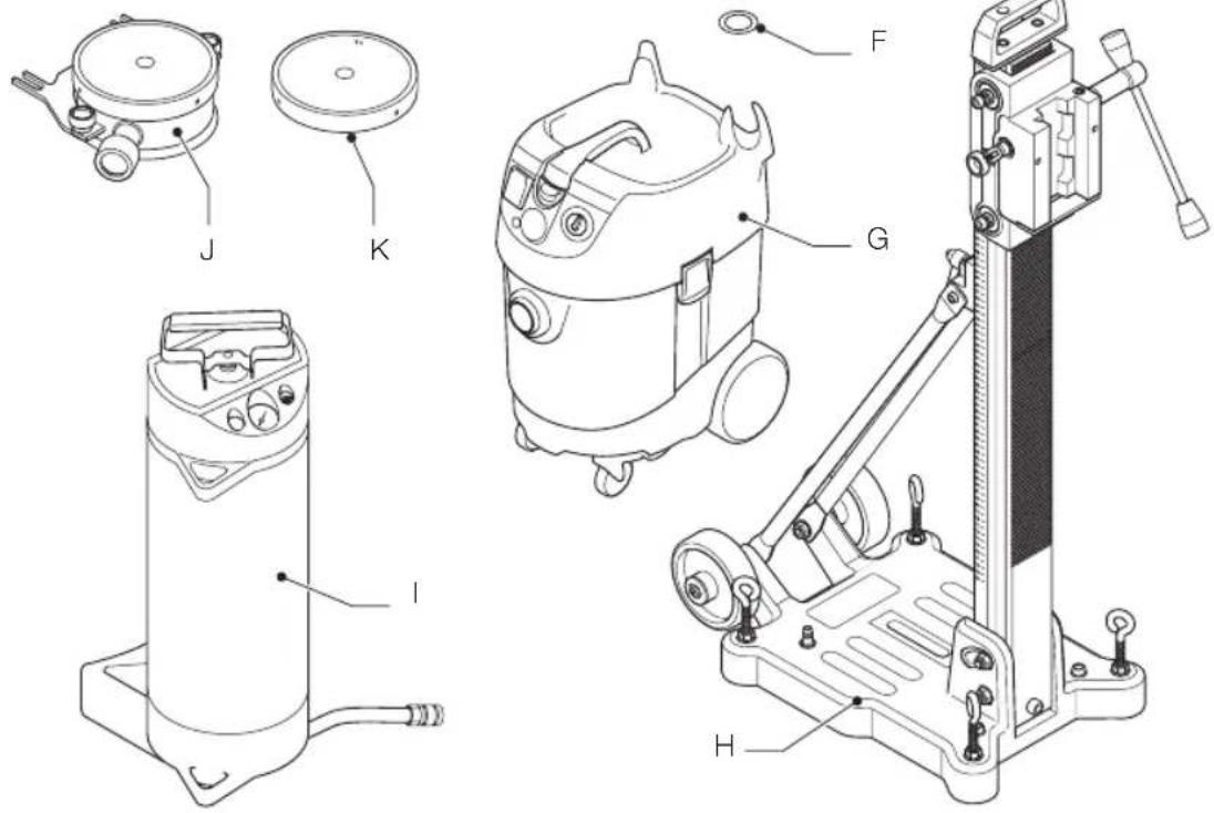
OPTIONAL ACCESSORIES (FIG. 2)
F. D215854 Set of copper rings (5 pcs)
G. D27902 Dust extractor
H. D215851 Drill stand
I. D215824 Water pump
J. D215852 Water collection ring (for use with D215851)
K. D215853 Spare seal for water collection ring (3 pcs) (for use with D215852)
INTENDED USE
Your D21585 diamond drilling machine has been designed for wet drilling into masonry materials such as brick, breeze block, etc., as well as engineered bricks, stone concrete and reinforced concrete with wet diamond core bits and a water supply. The machine should not be used for dry drilling applications.
The machine can only be used on a drill stand. The machine should never be used in handheld applications.
DO NOT use under wet conditions or in presence of flammable liquids or gases.
These diamond drills are professional power tools.
DO NOT let children come into contact with the tool. Supervision is required when inexperienced operators use this tool.
- Young children and the infirm. This appliance is not intended for use by young children or infirm persons without supervision.
- This product is not intended for use by persons (including children) suffering from diminished physical, sensory or mental abilities; lack of experience, knowledge or skills unless they are supervised by a person responsible for their safety. Children should never be left alone with this product.
Torque Limiting Clutch
This tool is equipped with a torque limiting clutch that reduces the maximum torque reaction transmitted to the operator in case of jamming of a drill bit. This feature also prevents the gearing and electric motor from stalling. The torque limiting clutch has been factory-set and cannot be adjusted.
Electronic Overload Protection (fig. 1)
The electronic overload protection offers additional safety: if the current approaches a certain limit, the warning indicator LED (B) lights up to indicate that the machine switches into overload mode if operation is continued at the same pressure level. Reduced operator pressure on the machine makes the electronics switch back into normal mode.
If continuous overload pressure is applied, the machine switches off. Thus, overheating of the motor windings is avoided. The machine is operational again after the load has been released.
Thermal Protection
After the machine has worked in overload for a long period of time, the thermal protection shuts off the machine to protect the motor. The machine will be operational after the thermal protection has cooled down. The time of cooling down depends on the overheating of the motor and the ambient temperature.
Water Supply
The integrated water swivel works directly through the motor shaft to provide continuous cooling of the core bit in wet drilling applications.
Electrical Safety
The electric motor has been designed for one voltage only. Always check that the power supply corresponds to the voltage on the rating plate.
Your DEWALT tool is grounded (class I) in accordance with EN61029; therefore no earth wire is required.

WARNING: 115 V units have to be operated via a fail-safe isolating transformer with an earth screen between the primary and secondary winding.
In case of cord or plug replacement, the tool must only be repaired by an authorized service agent or by a qualified electrician.
Using an Extension Cable
If an extension cable is required, use an approved 3-core extension cable suitable for the power input of this tool (see technical data). The minimum conductor size is 1.5 mm ^2 ; the maximum length is 30 m.
When using a cable reel, always unwind the cable completely.
Mains Plug Replacement (U.K. & Ireland Only)
If a new mains plug needs to be fitted:
• Safely dispose of the old plug.
- Connect the brown lead to the live terminal in the plug.
- Connect the blue lead to the neutral terminal.
- Connect the yellow/green lead to the earth terminal.
Follow the fitting instructions supplied with good quality plugs. Recommended fuse: 13 A.
Fitting a Mains Plug to 115 V Units (U.K. & Ireland only)
- The plug should be fitted by a competent person. If you are in doubt, contact an authorized DEWALT repair agent or a qualified electrician.
- The plug fitted should comply with BS EN 60309 (BS4343), 16 Amps, earthing contact position 4h.
DI-switch (in-line protector PRCD) (fig. 1)
The machine is equipped with a portable residual current device (PRCD) (R), which protects the user against electric shock by interrupting the circuit when a leakage current of 10 mA or greater is detected. For 115 V units the rated leakage current is 6 mA.

WARNING: Never operate the machine without the PRCD in place. Do not use the machine if the PRCD does not function properly. For the PRCD to work, the machine must be connected to an earthed wall socket.
TO SWITCH ON THE RCD
I = ON (red LED lights up).
Switch on the machine (also refer to the section Switching On and Off).
To switch off, proceed in reverse order.
TO TEST THE RCD
O = Test button: the switch must break the circuit (machine switches off).
WARNING:
- In the test mode the switch does not break the circuit, we recommend that the unit is inspected by an authorized DEWALT repair agent.
- It is not permitted to make any modifications to the machine, in particular it is not allowed to open the PRCD or to repair or replace the cable.
- Never use the PRCD as a main switch. Always switch the PRCD under no load condition.
ASSEMBLY AND ADJUSTMENTS

IG: To reduce the risk of injury, turn unit off and disconnect machine from power source before installing and removing accessories, before adjusting or changing set-ups or when making repairs. Be sure the trigger switch is in the OFF position. An accidental start-up can cause injury.
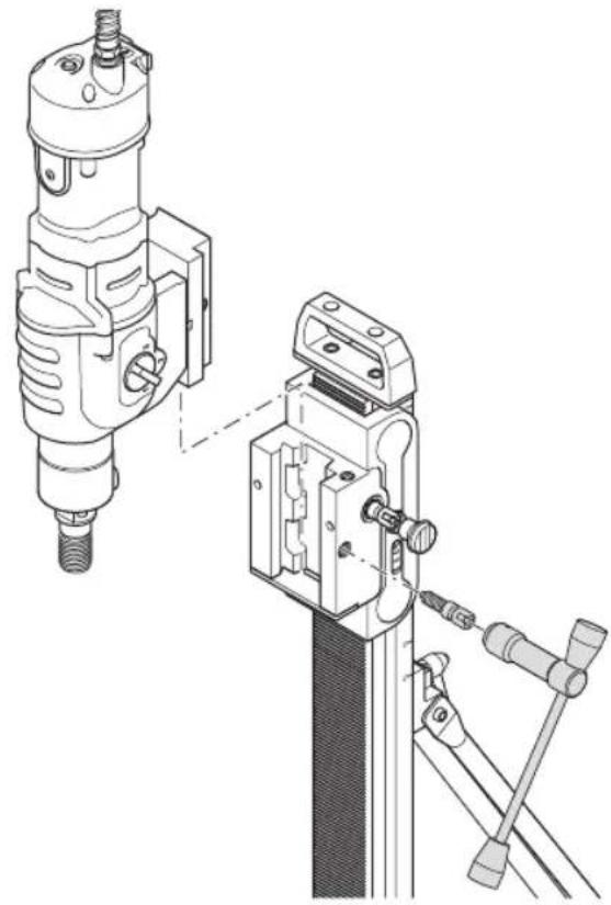
Fitting the Drill to the Stand (fig. 3)
The machine has to be fitted to the D215851 stand by means of the mounting bracket supplied with the stand.
WARNING: Also refer to the drill stand manual.
-
Fit the mounting bracket to the base of the machine.
-
Carefully place the machine with the bracket into the bracket holder on the stand as shown.
-
Secure the machine to the stand by tightening the bolt with the feed handle.

WARNING: Always mount your drill firmly to prevent movement.
Mounting and Removing an Accessory (fig. 4)
This tool uses threaded core bits and adaptors which thread directly onto the spindle (D).
We recommend to use professional accessories only.
- Choose the appropriate core bit for wet drilling.
- Follow the core bit or manufacturer's recommendations for mounting the accessory. You may require an adaptor to fit the bit onto the spindle.
- Make sure to place a copper ring (F) between the spindle and the core bit to facilitate removal of the core bit after use.
- Hold the spindle using the open-ended wrench (L) and tighten the core bit (M) by rotating clockwise using the open-ended wrench (N).

WARNING: Make sure the entire assembly is tight before starting the operation.
Three Gear Selector (fig. 1)
The tool is fitted with a three gear selector (C) to vary the speed/torque ratio.
- Release the switch and select the required position after the motor has come to a complete standstill.
- Always align the selector with the marks on the gear housing.
- Refer to the technical data to choose the appropriate gear according to the diameter of the core bit and the material to be drilled.
- Do not change gears at full speed or during use.
Connecting to a Water Supply (fig. 5)
WARNING:
- Never use the tool without the PRCD delivered with the tool.
- Replacement of the plug or the supply cord shall always be carried out by the manufacturer of the tool or his service organization.
-
Keep water clear of the electrical parts of the tool and away from persons in the working area.
-
Check that the water hose (P) has been tightened firmly into the fitting (E).
-
Close the water tap (Q).
-
Connect the water hose to an appropriate water supply system.

WARNING: Make sure that the pressure of the water supply is below the max. pressure as stated in the technical data.
Regulating the Water Flow (fig. 5)
The water tap (Q) on the water hose can be adjusted to regulate the flow of cooling water towards the drill bit.
- To reduce the flow, turn the tap clockwise.
- to increase the flow, turn the tap counterclockwise.
Prior to operation
- Mount the appropriate accessory.
- Mark the spot where the hole is to be drilled.
OPERATION
Instructions for Use
WARNING: Always observe the safety instructions and applicable regulations. WARNING: To reduce the risk of serious personal injury, turn tool off and disconnect tool from power source before making any adjustments or removing/installing attachments or accessories. Be sure the trigger switch is in the OFF position. An accidental start-up can cause injury

- For proper function, make sure the environment temperature is not too cold, machine and accessory is well maintained and the drill core bit size is suitable for this machine.
ENGLISH
• Always observe the safety instructions and applicable regulations.
- Be aware of the location of pipework and wiring.
- Apply only a gentle pressure to the tool. Excessive force does not speed up drilling but decreases tool performance and may shorten tool life.
Proper Hand Position (fig. 6)

WARNING: To reduce the risk of serious personal injury, ALWAYS use proper hand position as shown.

WARNING: To reduce the risk of serious personal injury, ALWAYS hold securely in anticipation of a sudden reaction.
Proper hand position requires one hand on the top of the drill stand, with the other hand on the stand handle.
Switching On and Off (fig. 1)
To switch the tool on, set the on/off switch (A) to position I.
To switch the tool off, set the on/off switch (A) to position 0.
General Tips for Drilling with Diamond Core Bits

G: Follow the core bit or manufacturer's recommendations for using the accessory.
NOTE: The use of a centredrill is not necessary.
- Switch on the drill motor.
- Slowly feed the accessory into the workpiece using the feed handle.
- At the start of the cut, apply light pressure to allow the accessory to perform the initial groove.
- Continue applying sufficient pressure to achieve a smooth progressive cut. Do not force.
- Take extra care when the accessory is about to break through the surface to prevent splintering.
- Always switch off the tool when work is finished and before unplugging.

WARNING: Do not mix or stir inflammable liquids labelled accordingly.
Wet Drilling
-
Connect the machine to an appropriate water supply system.
-
Adjust the water flow as necessary.
- Proceed as described above.

WARNING: If any water comes out of the drainage hole at the gear neck, stop the work immediately and have the machine repaired by an authorized repair agent.
MAINTENANCE
Your DEWALT power tool has been designed to operate over a long period of time with a minimum of maintenance. Continuous satisfactory operation depends upon proper tool care and regular cleaning.

IG: To reduce the risk of injury, turn unit off and disconnect machine from power source before installing and removing accessories, before adjusting or changing set-ups or when making repairs. Be sure the trigger switch is in the OFF position. An accidental start-up can cause injury.
Regularly take the tool to an authorized repair agent for inspection. This includes checking the carbon brushes, topping up oil in the gearcase and replacement of the gearcase sealing ring.
Troubleshooting
If your tool seems not to operate properly, follow the instructions below. If this does not solve the problem, please contact your repair agent.
Core bit does not cut
Material too hard for core bit
- Choose a more appropriate core bit (with softer segments).
- Apply wet drilling when appropriate.
Segments look glazed and polished
- Drill in abrasive material to re-expose diamond segments.
Evacuated water too clear and too fluid
Water flow slows down the cutting action and prevents the diamond segments to self-sharpen.
- Reduce water flow.
Rotating speed not appropriate
- Refer to the technical data for proper speed ratings.
Dust accumulating in core bit
Accumulating dust slows down the drilling speed.
- Use the appropriate dust extraction device.
- Disengage drill bit regularly to evacuate cuttings.
Segments and core are burnt
- Increase water flow.
Segments wear too fast
- Choose a more appropriate core bit (with harder segments).
- Reduce the pressure applied on the core bit.

Lubrication
Your power tool requires no additional lubrication.

Cleaning

WARNING: Blow dirt and dust out of the main housing with dry air as often as dirt is seen collecting in and around the air vents. Wear approved eye protection and approved dust mask when performing this procedure.

WARNING: Never use solvents or other harsh chemicals for cleaning the non-metallic parts of the tool. These chemicals may weaken the materials used in these parts. Use a cloth dampened only with water and mild soap. Never let any liquid get inside the tool; never immerse any part of the tool into a liquid.
Optional Accessories

WARNING: Since accessories, other than those offered by DEWALT, have not been tested with this product, use of such accessories with this tool could be hazardous. To reduce the risk of injury, only DEWALT, recommended accessories should be used with this product.
Consult your dealer for further information on the appropriate accessories.
DUST EXTRACTION SYSTEM (FIG. 6)
The D27902 dust extractor (G) ensures a proper and safe discharge of dust in all drilling applications. The D215852 water collection ring (J) is required to accommodate the assembly for wet drilling applications.
WATER PUMP (FIG. 6)
Removing debris from the working area and cooling the core bit in wet applications, the D215824 water pump (I) ensures water supply where main water supply is not available.
DRILL STAND (FIG. 6)
The D215851 drill stand (H) enables a quick set-up for stationary use of your diamond drill.

WARNING: DO NOT use the stand with a vacuum pump on a wall or ceiling.
Protecting the Environment
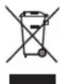
Separate collection. Products and batteries marked with this symbol must not be disposed of with normal household waste.
Products and batteries contain materials that can be recovered or recycled reducing the demand for raw materials. Please recycle electrical products and batteries according to local provisions. Further information is available at www.2helpU.com.
TALADRO DE PUNTA DE DIAMANTE D21585
¡Enhorabuena!
ACCESSOIRES EN OPTION (FIG. 2)
VALGFRITT TILBEH∅R (FIG. 2)
F. D215854 Sett med kobberringer (5 stk.)
G. D27902 Støvavsug
H. D215851 Drillstativ
I. D215824 Vannpumpe
J. D215852
I = PÅ (rød LCD lyser).
Segmentene slites for fort
- Velg et mer passende kjernebor (med hardere segmenter).
- Reduser trykket på kjerneboret.

Smøring
Director de Engenharia
DEWALT, Richard-Klinger-Strase 11,
D-65510, Idstein, Germany
20.04.16

The Date Code which also includes the year of manufacture, is printed into the motor housing.
Exempel:
2016 XX XX
Tillverkningsår
Paketets innehåll
Paketet innehåller: