DCN694 - Stapler DEWALT - Free user manual and instructions
Find the device manual for free DCN694 DEWALT in PDF.

| Product Type | Cordless Metal Connector Nailer |
| Brand | DeWalt |
| Model | DCN694 |
| Rated Voltage | 18 V DC |
| Battery Type | Li-Ion (compatible DCB180, DCB181, DCB182, DCB183, DCB183B, DCB184, DCB184B, DCB185) |
| Weight (without battery) | 8.0 kg |
| Magazine Angle | 33° |
| Fastener Length (profile 1) | 35 mm |
| Shank Diameter | 3.4–4.0 mm |
| Fastener Angle | 30–35° |
| Head Geometry | Full Round |
| Fastener Collation | Paper Tape |
| Operating Modes | Sequential, Sequential Rapid Cycle |
| Depth Adjustment | Depth Adjustment Wheel |
| Trigger Lock | Yes, with locking device |
| Dry-Fire Lockout | Yes, integrated |
| LED Indicators | Low battery, jam/stall, hot tool |
| Sound Pressure Level (L_PA) | 87 dB(A) |
| Sound Power Level (L_WA) | 98 dB(A) |
| Vibration Emission Value (a_h) | < 2.5 m/s² |
| Compatible Chargers | DCB105, DCB107, DCB112, DCB113, DCB115 |
| Maintenance | Regular cleaning of ventilation slots with compressed air |
| Lubrication | No additional lubrication required |
| Included Accessories (model P2) | Charger, 2 battery packs, replacement locating tip, accessory kit |
Frequently Asked Questions - DCN694 DEWALT
User questions about DCN694 DEWALT
0 question about this device. Answer the ones you know or ask your own.
Ask a new question about this device
Download the instructions for your Stapler in PDF format for free! Find your manual DCN694 - DEWALT and take your electronic device back in hand. On this page are published all the documents necessary for the use of your device. DCN694 by DEWALT.
USER MANUAL DCN694 DEWALT
English (original instructions) 44
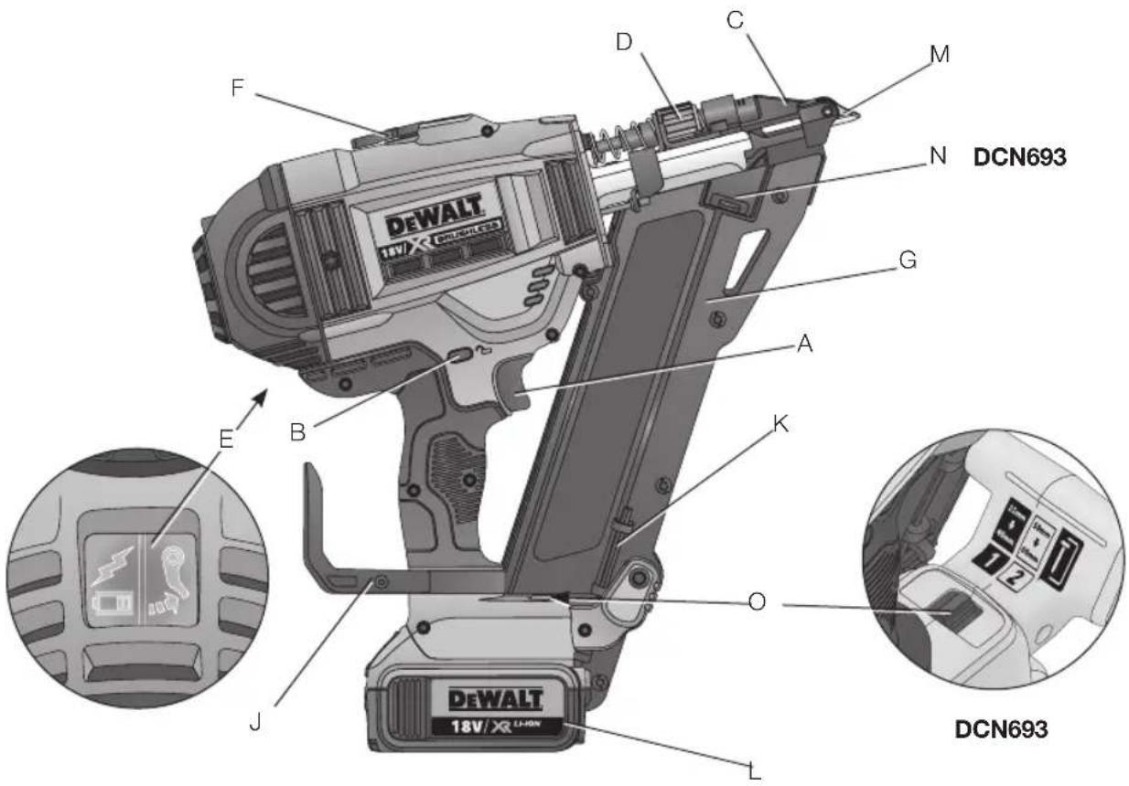
Figure 2
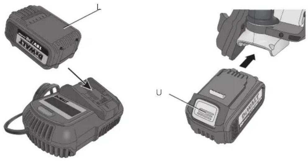
Figure 2a
 | Figure 5Figure 4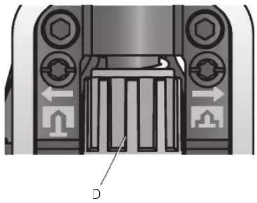 |
Figure 6 Figure 7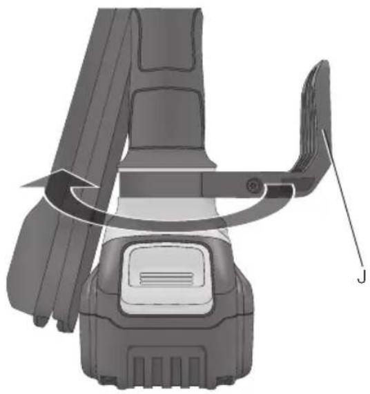 | 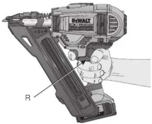 |
Figure 6 Figure 7
Figure 8
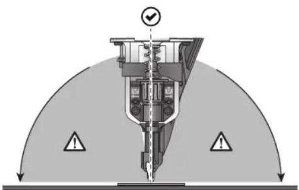
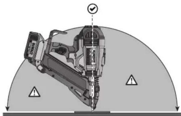
Figure 9
natural_image
Mechanical assembly diagram showing a cutting tool pressing into a workpiece on a flat base (no text or symbols visible)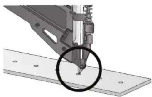
natural_image
Mechanical assembly diagram showing a cutting tool interacting with a flat plate (no text or symbols visible)Figure 10
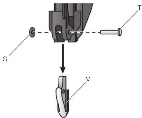
Figure 11a
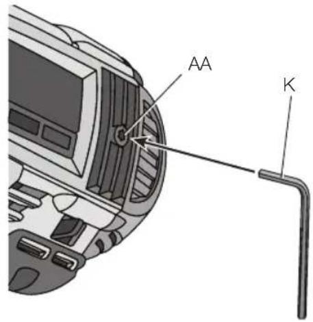
Figure 11b
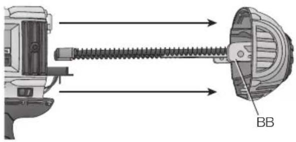
Figure 11c Figure 11d
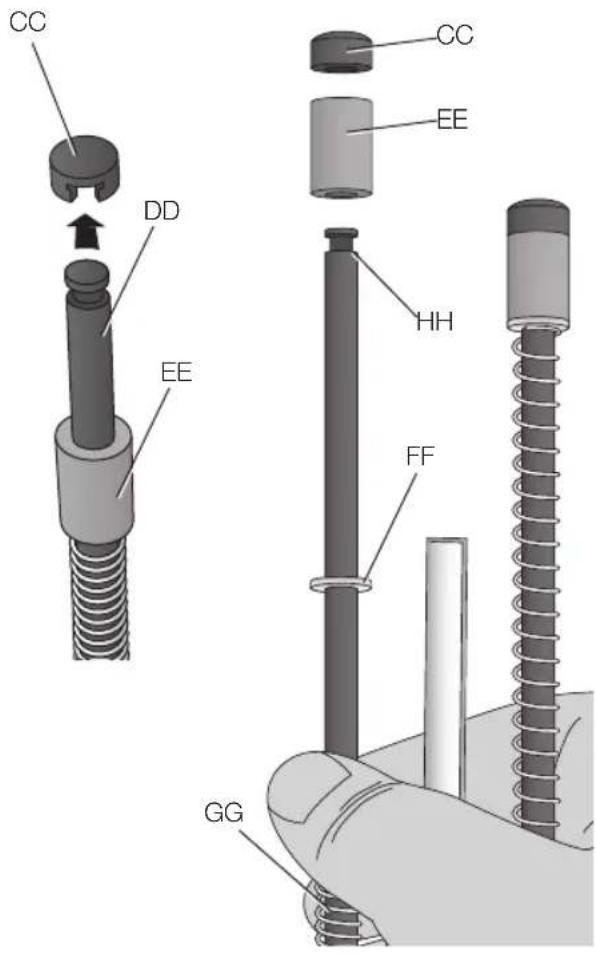
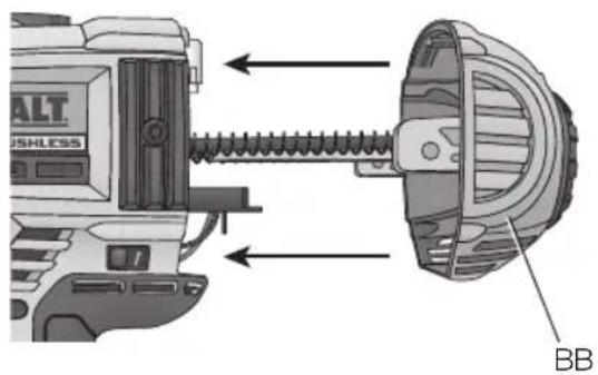
Figure 11e
TRÅDL∅S METALKONNEKTOR S∅MPISTOL DCN693, DCN694
Tillykke!
You have chosen a DEWALTtool. Years of experience, thorough product development and innovation make DEWALT one of the most reliable partners for professional power tool users.
Technical Data
| DCN693 DCN694 | |||
| Voltage V | DC | 18 18 | |
| Type 1 1 | |||
| Battery type Li-Ion Li-Ion | |||
| Actuating mode Sequential/ | RapidCycle Sequential | Sequential/RapidCycle Sequential | |
| Multi-Speed Yes No | |||
| Magazine angle 33^ 33^ | |||
| Fasteners | |||
| length (speed 1) | mm | 40 | 35 |
| length (speed 2) | mm | 50-60 | N/A |
| shank diameter | mm | 3.4-4.0 | 3.4-4.0 |
| angle | 30-35^ | 30-35^ | |
| head geometry | Full Round | Full Round | |
| collation type | Paper Tape | Paper Tape | |
| Weight (without battery pack) | kg | 8.0 | 8.0 |
| Noise values and vibration values (triax vector sum) according to EN60745: | |||
| L_PA (emission sound pressure level) | dB(A) | 87 87 | |
| L_WA (sound power level) | dB(A) | 98 98 | |
| K(uncertainty for the given sound level) | dB(A) | 3 3 | |
| Vibration emission value a_h = | m/s ^2 | < 2,5 < 2,5 | |
| Uncertainty K = | m/s ^2 | 1,5 | 1,5 |
The vibration emission level given in this information sheet has been measured in accordance with a standardised test given in EN60745 and may be used to compare one tool with another. It may be used for a preliminary assessment of exposure.

WARNING: The declared vibration emission level represents the main applications of the tool. However if the tool is used for different applications, with different accessories or poorly maintained, the vibration emission may differ. This may significantly increase the exposure level over the total working period.
An estimation of the level of exposure to vibration should also take into account the times when the tool is switched off or when it is running but not actually doing the job. This may significantly reduce the exposure level over the total working period.
Identify additional safety measures to protect the operator from the effects of vibration such as: maintain the tool and the accessories, keep the hands warm, organisation of work patterns.
Battery pack DCB180 DCB181 DCB182
| Battery type | Li-Ion | Li-Ion | Li-Ion | |
| Voltage | V_DC | 18 | 18 | 18 |
| Capacity | Ah | 3.0 | 1.5 | 4.0 |
| Weight | kg | 0.64 | 0.35 | 0.61 |
| Battery pack | DCB183/B | DCB184/B | DCB185 | |
| Battery type | Li-Ion | Li-Ion | Li-Ion | |
| Voltage | V_DC | 18 | 18 | 18 |
| Capacity | Ah | 2.0 | 5.0 | 1.3 |
| Weight | kg | 0.40/0.45 | 0.62/0.67 | 0.35 |
| Charger | DCB105 | |||
| Mains voltage | V_AC | 230 | ||
| Battery type | 10.8/14.4/18 Li-Ion | |||
| Approx. charging time of battery packs | min | 25 (1.3 Ah) | 30 (1.5 Ah) | 40 (2.0 Ah) |
| 55 (3.0 Ah) | 70 (4.0 Ah) | 90 (5.0 Ah) | ||
| Weight kg | 0.49 | |||
| Charger | DCB107 | |||
| Mains voltage | V_AC | 230 | ||
| Battery type | 10.8/14.4/18 Li-Ion | |||
| Approx. charging time of battery packs | min | 60 (1.3 Ah) | 70 (1.5 Ah) | 90 (2.0 Ah) |
| 140 (3.0 Ah) | 185 (4.0 Ah) | 240 (5.0 Ah) | ||
| Weight | kg | 0.29 | ||
| Charger | DCB112 | |||
| Mains voltage V | V_AC | 230 | ||
| Battery type | 10.8/14.4/18 Li-Ion | |||
| Approx. charging time of battery packs | min | 40 (1.3 Ah) | 45 (1.5 Ah) | 60 (2.0 Ah) |
| 90 (3.0 Ah) | 120 (4.0 Ah) | 150 (5.0 Ah) | ||
| Weight | kg | 0.36 | ||
| Charger | DCB113 | |||
| Mains voltage | V_AC | 230 | ||
| Battery type | 10.8/14.4/18 Li-Ion | |||
| Approx. charging time of battery packs | min | 30 (1.3 Ah) | 35 (1.5 Ah) | 50 (2.0 Ah) |
| 70 (3.0 Ah) | 100 (4.0 Ah) | 120 (5.0 Ah) | ||
| Weight kg 0.4 | ||||
| Charger | DCB115 | |||
| Mains voltage | V_AC | 230 | ||
| Battery type | 10.8/14.4/18 Li-Ion | |||
| Approx. charging time of battery packs | min | 22 (1.3 Ah) | 22 (1.5 Ah) | 30 (2.0 Ah) |
| 45 (3.0 Ah) | 60 (4.0 Ah) | 75 (5.0 Ah) | ||
| Weight | kg 0.5 | |||
Fuses:
Europe 230V tools 10 Amperes. mains
U.K. & Ireland 230V tools 3 Amperes. in plugs
Definitions: Safety Guidelines
The definitions below describe the level of severity for each signal word. Please read the manual and pay attention to these symbols.

DANGER: Indicates an imminently hazardous situation which, if not avoided, will result in death or serious injury.

WARNING: Indicates a potentially hazardous situation which, if not avoided, could result in death or serious injury.

CAUTION: Indicates a potentially hazardous situation which, if not avoided, may result in minor or moderate injury.
NOTICE: Indicates a practice not related to personal injury which, if not avoided, may result in property damage.

risk of electric shock.

risk of fire.
EC-Declaration of Conformity MACHINERY DIRECTIVE

18V XR LI-ION CORDLESS METAL CONNECTOR NAILER DCN693, DCN694
DEWALT declares that these products described under Technical Data are in compliance with: 2006/42/EC, EN60745-1:2009 +A11:2010, EN60745-2-16:2010.
These products also comply with Directive 2004/108/EC (until 19.04.2016), 2014/30/EU (from 20.04.2016) and 2011/65/EU. For more information, please contact DEWALTat the following address or refer to the back of the manual.
The undersigned is responsible for compilation of the technical file and makes this declaration on behalf of DEWALT.

ENGLISH
Markus Rompel
Director Engineering
D-65510, Idstein, Germany
16.11.2015

G: To reduce the risk of injury,
read the instruction manual.
General Power Tool Safety Warnings

WARNING: Read all safety warnings and all instructions. Failure to follow the warnings and instructions may result in electric shock, fire and/or serious injury.
SAVE ALL WARNINGS AND INSTRUCTIONS FOR FUTURE REFERENCE
The term "power tool" in the warnings refers to your mains-operated (corded) power tool or battery-operated (cordless) power tool.
1) WORK AREA SAFETY
a) Keep work area clean and well lit.
Cluttered or dark areas invite accidents.
b) Do not operate power tools in explosive atmospheres, such as in the presence of flammable liquids, gases or dust. Power tools create sparks which may ignite the dust or fumes.
c) Keep children and bystanders away while operating a power tool. Distractions can cause you to lose control.
2) ELECTRICAL SAFETY
a) Power tool plugs must match the outlet. Never modify the plug in any way. Do not use any adapter plugs with earthed (grounded) power tools.
Unmodified plugs and matching outlets will reduce risk of electric shock.
b) Avoid body contact with earthed or grounded surfaces such as pipes, radiators, ranges and refrigerators. There is an increased risk of electric shock if your body is earthed or grounded.
c) Do not expose power tools to rain or wet conditions. Water entering a power tool will increase the risk of electric shock.
d) Do not abuse the cord. Never use the cord for carrying, pulling or unplugging the power tool. Keep cord away from heat, oil, sharp edges or moving parts. Damaged or entangled cords increase the risk of electric shock.
e) When operating a power tool outdoors, use an extension cord suitable for outdoor use. Use of a cord suitable for outdoor use reduces the risk of electric shock.
f) If operating a power tool in a damp location is unavoidable, use a residual current device (RCD) protected supply. Use of an RCD reduces the risk of electric shock.
3) PERSONAL SAFETY
a) Stay alert, watch what you are doing and use common sense when operating a power tool. Do not use a power tool while you are tired or under the influence of drugs, alcohol or medication. A moment of inattention while operating power tools may result in serious personal injury.
b) Use personal protective equipment. Always wear eye protection. Protective equipment such as dust mask, non-skid safety shoes, hard hat, or hearing protection used for appropriate conditions will reduce personal injuries.
c) Prevent unintentional starting. Ensure the switch is in the off position before connecting to power source and/or battery pack, picking up or carrying the tool. Carrying power tools with your finger on the switch or energising power tools that have the switch on invites accidents.
d) Remove any adjusting key or wrench before turning the power tool on. A wrench or a key left attached to a rotating part of the power tool may result in personal injury.
e) Do not overreach. Keep proper footing and balance at all times. This enables better control of the power tool in unexpected situations.
f) Dress properly. Do not wear loose clothing or jewellery. Keep your hair, clothing and gloves away from moving parts. Loose clothes, jewellery or long hair can be caught in moving parts.
g) If devices are provided for the connection of dust extraction and collection facilities, ensure these are connected and properly used. Use of dust collection can reduce dust-related hazards.
4) POWER TOOL USE AND CARE
a) Do not force the power tool. Use the correct power tool for your application.
The correct power tool will do the job better and safer at the rate for which it was designed.
b) Do not use the power tool if the switch does not turn it on and off. Any power tool that cannot be controlled with the switch is dangerous and must be repaired.
c) Disconnect the plug from the power source and/or the battery pack from the power tool before making any adjustments, changing accessories, or storing power tools. Such preventive safety measures reduce the risk of starting the power tool accidentally.
d) Store idle power tools out of the reach of children and do not allow persons unfamiliar with the power tool or these instructions to operate the power tool. Power tools are dangerous in the hands of untrained users.
e) Maintain power tools. Check for misalignment or binding of moving parts, breakage of parts and any other condition that may affect the power tool's operation. If damaged, have the power tool repaired before use. Many accidents are caused by poorly maintained power tools.
f) Keep cutting tools sharp and clean. Properly maintained cutting tools with sharp cutting edges are less likely to bind and are easier to control.
g) Use the power tool, accessories and tool bits etc., in accordance with these instructions taking into account the working conditions and the work to be performed. Use of the power tool for operations different from those intended could result in a hazardous situation.
5) BATTERY TOOL USE AND CARE
a) Recharge only with the charger specified by the manufacturer. A charger that is suitable for one type of battery pack may create a risk of fire when used with another battery pack.
b) Use power tools only with specifically designated battery packs. Use of any other battery packs may create a risk of injury and fire.
c) When battery pack is not in use, keep it away from other metal objects like paper clips, coins, keys, nails, screws or other small metal objects that can make a connection from one terminal to another. Shorting the battery terminals together may cause burns or a fire.
d) Under abusive conditions, liquid may be ejected from the battery; avoid contact. If contact accidentally occurs, flush with water. If liquid contacts eyes, additionally seek medical help. Liquid ejected from the battery may cause irritation or burns.
6) SERVICE
a) Have your power tool serviced by a qualified repair person using only identical replacement parts. This will ensure that the safety of the power tool is maintained.
Safety Instructions for Cordless Nailers
- Always assume that the tool contains fasteners. Careless handling of the nailer can result in unexpected firing of fasteners and personal injury.
- Do not point the tool towards yourself or anyone nearby. Unexpected triggering will discharge the fastener causing an injury.
- Do not actuate the tool unless the tool is placed firmly against the workpiece. If the tool is not in contact with the workpiece, the fastener may be deflected away from your target.
- Disconnect the tool from the power source when the fastener jams in the tool. While removing a jammed fastener, the nailer may be accidentally activated if it is plugged in.
- Do not use this nailer for fastening electrical cables. It is not designed for electric cable installation and may damage the insulation of electric cables thereby causing electric shock or fire hazards.
- Do not use the tool as a hammer. For exemptions check your local national workplace regulations.
• Always check local workplace regulations.
• Always wear safety glasses.
• Always wear ear protection.
- Only use fasteners of the type specified in the manual.
- Do not use any stands for mounting the tool to a support.
- Do not disassemble or block any parts of the fastener driving tool such as the contact trip.
- Prior to each operation check that the safety and triggering mechanism is functioning properly and that all nuts and bolts are tight.
- Never actuate the fastener driving tool into free space.
- In the work area, carry the tool at the workplace using only one handle, and never with the trigger actuated.
ENGLISH
- Consider the conditions in the work area. Fasteners can penetrate thin work pieces or slip off corners and edges of the work piece, and thus put people at risk.
- Do not drive fasteners close to the edge of the workpiece.
- Do not drive fasteners on top of other fasteners.
Residual Risks
The following risks are inherent to the use of these machines:
– Injuries caused by improper handling of the tool.
– Loss of control due to not gripping tool firmly.
- Muscle strain of arms and hands, especially when working overhead. Always take regular breaks when working for long periods of time.
In spite of the application of the relevant safety regulations and the implementation of safety devices, certain residual risks cannot be avoided. These are:
- Impairment of hearing.
– Risk of personal injury due to flying particles.
– Risk of personal injury due to prolonged use.
– Loss of control caused by recoil.
– Risk of injury caused by pinch points, sharp edges and improper handling of workpiece.
– Risk of injury caused by sharp edges when changing nails or inserting nail sticks.
Markings on Tool
The following pictograms are shown on the tool:

Read instruction manual before use.

Wear ear protection.

Wear eye protection.

Visible radiation. Do not stare into light.

Length of nails.

Nailthickness.

Loading capacity.

Suitable nail collation angle.
DATE CODE POSITION
The date code, which also includes the year of manufacture, is printed into the housing.
Example:
2016 XX XX
Year of Manufacture
Important Safety Instructions for All Battery Chargers
SAVE THESE INSTRUCTIONS: This manual contains important safety and operating instructions for compatible battery chargers (refer to Technical Data).
- Before using charger, read all instructions and cautionary markings on charger, battery pack, and product using battery pack.

WARNING: Shock hazard. Do not allow any liquid to get inside charger. Electric shock may result.

G: We recommend the use of a residual current device with a residual current rating of 30mA or less.

CAUTION: Burn hazard. To reduce the risk of injury, charge only DEWALT rechargeable batteries. Other types of batteries may burst causing personal injury and damage.

CAUTION: Children should be supervised to ensure that they do not play with the appliance.
NOTICE: Under certain conditions, with the charger plugged into the power supply, the exposed charging contacts inside the charger can be shorted by foreign material. Foreign materials of a conductive nature such as, but not limited to, steel wool, aluminum foil or any buildup of metallic particles should be kept away from charger cavities. Always unplug the charger from the power supply when there is no battery pack in the cavity. Unplug charger before attempting to clean
- DO NOT attempt to charge the battery pack with any chargers other than the ones in this manual. The charger and battery pack are specifically designed to work together.
-
These chargers are not intended for any uses other than charging DEWALT rechargeable batteries. Any other uses may result in risk of fire, electric shock or electrocution.
-
Do not expose charger to rain or snow.
- Pull by plug rather than cord when disconnecting charger. This will reduce risk of damage to electric plug and cord.
- Make sure that cord is located so that it will not be stepped on, tripped over, or otherwise subjected to damage or stress.
- Do not use an extension cord unless it is absolutely necessary. Use of improper extension cord could result in risk of fire, electric shock, or electrocution.
- Do not place any object on top of charger or place the charger on a soft surface that might block the ventilation slots and result in excessive internal heat. Place the charger in a position away from any heat source. The charger is ventilated through slots in the top and the bottom of the housing.
- Do not operate charger with damaged cord or plug—have them replaced immediately.
- Do not operate charger if it has received a sharp blow, been dropped, or otherwise damaged in any way. Take it to an authorised service centre.
- Do not disassemble charger; take it to an authorised service centre when service or repair is required. Incorrect reassembly may result in a risk of electric shock, electrocution or fire.
- In case of damaged power supply cord the supply cord must be replaced immediately by the manufacturer, its service agent or similar qualified person to prevent any hazard.
- Disconnect the charger from the outlet before attempting any cleaning. This will reduce the risk of electric shock. Removing the battery pack will not reduce this risk.
- NEVER attempt to connect two chargers together.
- The charger is designed to operate on standard 230V household electrical power. Do not attempt to use it on any other voltage. This does not apply to the vehicular charger.
SAVE THESE INSTRUCTIONS
Chargers
The DCB105, DCB107, DCB112, DCB113 and DCB115 chargers accept 10.8V, 14.4V and 18V Li-Ion XR (DCB140, DCB141, DCB142, DCB143, DCB144, DCB145, DCB180, DCB181, DCB182, DCB183, DCB183B, DCB184, DCB184B and DCB185) battery packs.
DEWALT chargers require no adjustment and are designed to be as easy as possible to operate.
Charging Procedure (Fig. 2, 2a)
- Plug the charger into an appropriate outlet before inserting battery pack.
- Insert the battery pack (L) into the charger. The red (charging) light will blink continuously indicating that the charging process has started.
- The completion of charge will be indicated by the red light remaining ON continuously. The pack is fully charged and may be used at this time or left in the charger.
NOTE: To ensure maximum performance and life of lithium-ion batteries, charge the battery pack fully before first use.
Charging Process
Refer to the table below for the charge status of the battery pack.
Charge indicators: DCB105
| charging | — — — — — | |
| fully charged | — | |
| hot/cold pack delay | — • — • — • | |
| replace battery pack | • • • • • • • • • |
Charge indicators: DCB107, DCB112, DCB113, DCB115
| charging | |
| fully charged | |
| hot/cold pack delay* |
* DCB107, DCB112, DCB113, DCB115: The red light will continue to blink, but a yellow indicator light will be illuminated during this operation. Once the battery has reached an appropriate temperature, the yellow light will turn off and the charger will resume the charging procedure.
The compatible charger(S) will not charge a faulty battery pack. The charger will indicate faulty battery by refusing to light or by displaying problem pack or charger blink pattern.
NOTE: This could also mean a problem with a charger.
If the charger indicates a problem, take the charger and battery pack to be tested at an authorised service centre.
ENGLISH
HOT/COLD PACK DELAY
When the charger detects a battery that is too hot or too cold, it automatically starts a Hot/Cold Pack Delay, suspending charging until the battery has reached an appropriate temperature. The charger then automatically switches to the pack charging mode. This feature ensures maximum battery life.
A cold battery pack will charge at about half the rate of a warm battery pack. The battery pack will charge at that slower rate throughout the entire charging cycle and will not return to maximum charge rate even if the battery warms.
XR Li-Ion tools are designed with an Electronic Protection System that will protect the battery against overloading, overheating or deep discharge.
The tool will automatically turn off if the Electronic Protection System engages. If this occurs, place the lithium-ion battery on the charger until it is fully charged.
Important Safety Instructions for All Battery Packs
When ordering replacement battery packs, be sure to include catalog number and voltage.
The battery pack is not fully charged out of the carton. Before using the battery pack and charger, read the safety instructions below. Then follow charging procedures outlined.
READ ALL INSTRUCTIONS
- Do not charge or use battery in explosive atmospheres, such as in the presence of flammable liquids, gases or dust. Inserting or removing the battery from the charger may ignite the dust or fumes.
- Never force battery pack into charger. Do not modify battery pack in any way to fit into a non-compatible charger as battery pack may rupture causing serious personal injury.
- Charge the battery packs only in DEWALT chargers.
- DO NOT splash or immerse in water or other liquids.
- Do not store or use the tool and battery pack in locations where the temperature may reach or exceed 40 °C (104 °F) (such as outside sheds or metal buildings in summer).

WARNING: Never attempt to open the battery pack for any reason. If battery pack case is cracked or damaged,
do not insert into charger. Do not crush, drop or damage battery pack. Do not use a battery pack or charger that has received a sharp blow, been dropped, run over or damaged in any way (i.e., pierced with a nail, hit with a hammer, stepped on). Electric shock or electrocution may result. Damaged battery packs should be returned to service centre for recycling.

N: When not in use, place tool on its side on a stable surface where it will not cause a tripping or falling hazard. Some tools with large battery packs will stand upright on the battery pack but may be easily knocked over.
SPECIFIC SAFETY INSTRUCTIONS FOR LITHIUM-ION (LI-ION)
- Do not incinerate the battery pack even if it is severely damaged or is completely worn out. The battery pack can explode in a fire. Toxic fumes and materials are created when lithium-ion battery packs are burned.
- If battery contents come into contact with the skin, immediately wash area with mild soap and water. If battery liquid gets into the eye, rinse water over the open eye for 15 minutes or until irritation ceases. If medical attention is needed, the battery electrolyte is composed of a mixture of liquid organic carbonates and lithium salts.
- Contents of opened battery cells may cause respiratory irritation. Provide fresh air. If symptoms persist, seek medical attention.

WARNING: Burn hazard. Battery liquid may be flammable if exposed to spark or flame.
Transportation
DEWALT batteries comply with all applicable shipping regulations as prescribed by industry and legal standards which include UN Recommendations on the Transport of Dangerous Goods; International Air Transport Association (IATA) Dangerous Goods Regulations, International Maritime Dangerous Goods (IMDG) Regulations, and the European Agreement Concerning The International Carriage of Dangerous Goods by Road (ADR). Lithium-ion cells and batteries have been tested to section 38.3 of the UN Recommendations on the Transport of Dangerous Goods Manual of Tests and Criteria.
In most instances, shipping a DEWALT battery pack will be excepted from being classified as a fully regulated Class 9 Hazardous Material. In general, the two instances that require shipping Class 9 are:
- Air shipping more than two DEWALT lithium-ion battery packs when the package contains only battery packs (no tools), and
- Any shipment containing a lithium-ion battery with an energy rating greater than 100 watt hours (Wh). All lithium-ion batteries have the watt hour rating marked on the pack.
Regardless of whether a shipment is considered excepted or fully regulated, it is the shipper's responsibility to consult the latest regulations for packaging, labeling/marking and documentation requirements.
Transporting batteries can possibly cause fire if the battery terminals inadvertently come in contact with conductive materials. When transporting batteries, make sure that the battery terminals are protected and well insulated from materials that could contact them and cause a short circuit.
The information provided in this section of the manual is provided in good faith and believed to be accurate at the time the document was created. However, no warranty, expressed or implied, is given. It is the buyer's responsibility to ensure that its activities comply with the applicable regulations.
Battery Pack
BATTERY TYPE
The DCN693 and DCN693 operate on a 18 volt battery pack.
The DCB180, DCB181, DCB182, DCB183, DCB183B, DCB184, DCB184B or DCB185 battery packs may be used. Refer to Technical Data for more information.
Storage Recommendations
- The best storage place is one that is cool and dry away from direct sunlight and excess heat or cold. For optimum battery performance and life, store battery packs at room temperature when not in use.
- For long storage, it is recommended to store a fully charged battery pack in a cool, dry place out of the charger for optimal results.
NOTE: Battery packs should not be stored completely depleted of charge. The battery pack will need to be recharged before use.
Labels on Charger and Battery Pack
In addition to the pictographs used in this manual, the labels on the charger and the battery pack may show the following pictographs:


Read instruction manual before use.
See Technical Data for charging time.
Battery charging.
Battery charged.

Battery defective.

Hot/cold pack delay.

Do not probe with conductive objects.

Do not charge damaged battery packs.

Do not expose to water.

Have defective cords replaced immediately.

Charge only between 4 °C and 40 °C.
Only for indoor use.
Discard the battery pack with due care for the environment.

Charge DEWALT battery packs only with designated DEWALT chargers. Charging battery packs other than the designated DEWALT batteries with a DEWALT charger may make them burst or lead to other dangerous situations.

Do not incinerate the battery pack.
Package Contents
The package contains:
1 Metal connector nailer
1 Hole locating tip replacement (P2 models only)
ENGLISH
1 Charger (P2 models only)
2 Battery packs (P2 models only)
1 Kitbox (P2 models only)
1 Instruction manual
NOTE: Battery packs, chargers and kitboxes are not included in N versions.
- Check for damage to the tool, parts or accessories which may have occurred during transport.
• Take the time to thoroughly read and understand this manual prior to operation.
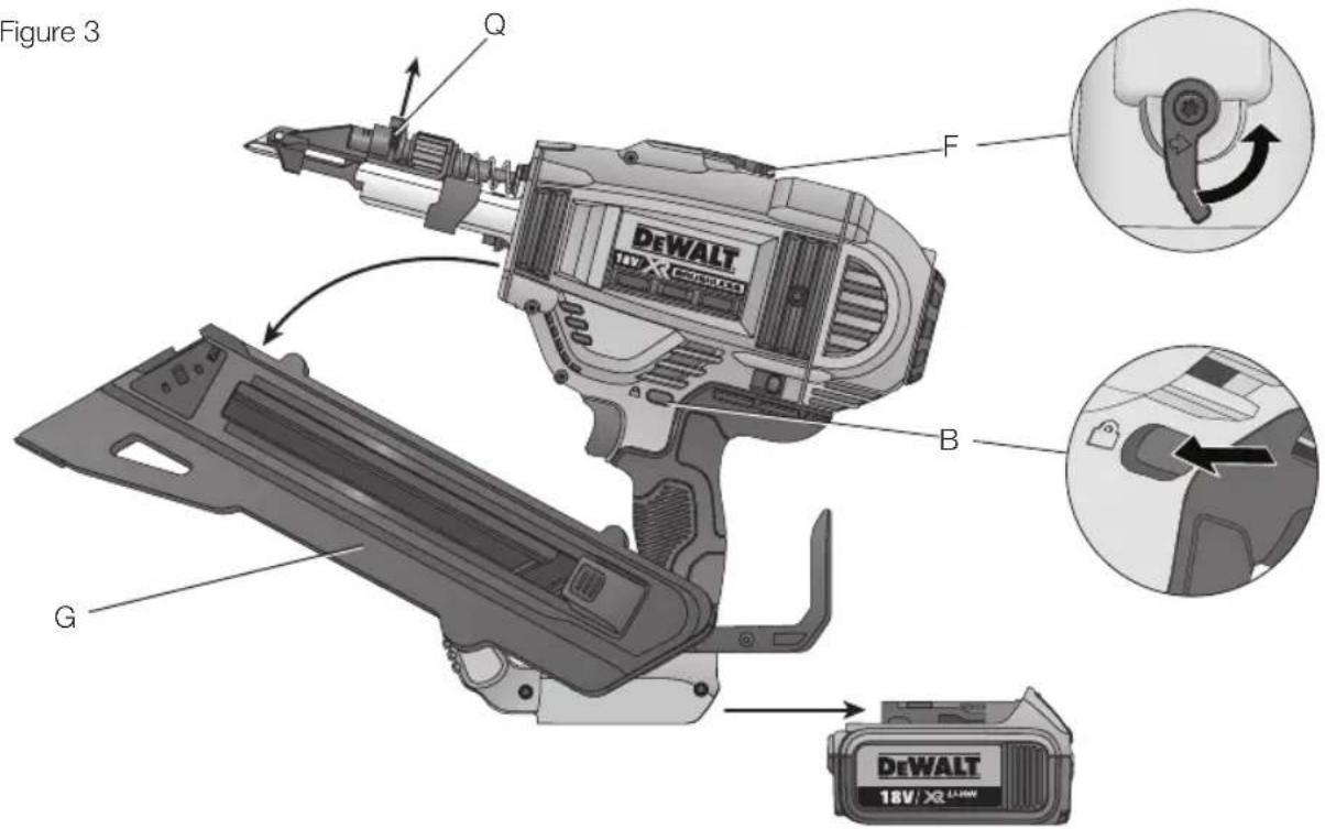
Description (Fig. 1)

WARNING: Never modify the power tool or any part of it. Damage or personal injury could result.
A. Trigger
B. Trigger safety lock-off
C. Contact trip
D. Depth adjustment wheel
E. Low battery and jam/stall indicator light
F. Stall release lever
G. Magazine
H. Pusher latch
- Mode select switch
J. Rotating rafter/belt hook
K. On-board hex wrench
L. Battery pack
M. Hole locating tip
N. Nail support lever (DCN693)
O. Nail length selector switch (DCN693)
INTENDED USE
The DCN693 and DCN694 cordless metal connector nailers have been designed ONLY for attaching metal hardware with pre-formed holes to wooden workpieces.
The cordless metal connector nailer is designed for sequential and RapidCycle sequential mode. Nailers designed for sequential only mode MAY BE used on scaffoldings, stairs, ladders or ladder-like constructions, e.g., roof laths.
Only fasteners recommended by the metal connector hardware manufacturer and meeting applicable building code requirements must be used in this tool to install connectors.
DO NOT use under wet conditions or in the presence of flammable liquids or gases.
These cordless nailers are professional power tools.
DO NOT let children come into contact with the tool. Supervision is required when inexperienced operators use this tool.
- Young children and the infirm. This appliance is not intended for use by young children or infirm persons without supervision.
- This product is not intended for use by persons (including children) suffering from diminished physical, sensory or mental abilities; lack of experience, knowledge or skills unless they are supervised by a person responsible for their safety. Children should never be left alone with this product.
Electrical Safety
The electric motor has been designed for one voltage only. Always check that the battery pack voltage corresponds to the voltage on the rating plate. Also make sure that the voltage of your charger corresponds to that of your mains.

Your DEWALTcharger is double insulated in accordance with EN60335; therefore no earth wire is required.
If the supply cord is damaged, it must be replaced by a specially prepared cord available through the DEWALT service organisation.
Mains Plug Replacement (U.K. & Ireland Only)
If a new mains plug needs to be fitted:
- Safely dispose of the old plug.
- Connect the brown lead to the live terminal in the plug.
- Connect the blue lead to the neutral terminal.

WARNING: No connection is to be made to the earth terminal.
Follow the fitting instructions supplied with good quality plugs. Recommended fuse: 3 A.
Using an Extension Cable
An extension cord should not be used unless absolutely necessary. Use an approved extension cable suitable for the power input of your charger (see Technical Data). The minimum conductor size is 1 mm ^2 ; the maximum length is 30 m.
When using a cable reel, always unwind the cable completely.
ASSEMBLY AND ADJUSTMENTS
WARNING: To reduce the risk of serious personal injury, turn tool off and disconnect battery pack before making any adjustments or removing/installing attachments or accessories. An accidental start-up can cause injury.
WARNING: Use only DEWALT battery packs and chargers.
Inserting and Removing the Battery Pack from the Tool (Fig. 2)
NOTE: Make sure your battery pack (L) is fully charged.
TO INSTALL THE BATTERY PACK INTO THE TOOL HANDLE
- Align the battery pack (L) with the rails inside the tool's handle.
- Slide it into the handle until the battery pack is firmly seated in the tool and ensure that you hear the lock snap into place.
TO REMOVE THE BATTERY PACK FROM THE TOOL
- Press the release button (U) and firmly pull the battery pack out of the tool handle.
- Insert battery pack into the charger as described in the charger section of this manual.
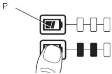
FUEL GAUGE BATTERY PACKS (FIG. 2, 2A)
Some DEWALT battery packs include a fuel gauge which consists of three green LED lights that indicate the level of charge remaining in the battery pack.
To actuate the fuel gauge, press and hold the fuel gauge button (P). A combination of the three green LED lights will illuminate designating the level of charge left. When the level of charge in the battery is below the usable limit, the fuel gauge will not illuminate and the battery will need to be recharged.
NOTE: The fuel gauge is only an indication of the charge left on the battery pack. It does not indicate tool functionality and is subject to variation based on product components, temperature and end-user application.
Rotating Rafter/Belt Hook (Fig. 6)
The rafter/belt hook (J) and can be easily positioned to the left or right of the tool to accommodate left-or right-handed users.
If use of the hook is not desired at all, it can be rotated to the front or back of the handle base.
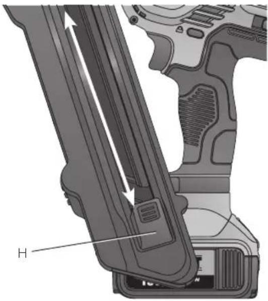
Loading the Tool (Fig. 4)
WARNING: Always engage the trigger safety lock-off (B) and disconnect battery pack before loading and unloading fasteners.
WARNING: Fasteners used to install metal connectors must meet the requirements of the applicable building codes and must be installed in compliance with code requirements and metal connector hardware supplier specifications. Failure to properly install connectors may result in structural failures.
- Slide the spring-loaded pusher latch (H) to the base of the magazine to lock it into place.
- Select an appropriate collated nail stick. (Refer to Technical Data.) DEWALT would always recommend that you use DEWALT branded first fix nails.
WARNING: Since accessories, other than those offered by DEWALT, have not been tested with this product, use of such accessories with this tool could be hazardous. To reduce the risk of injury, only DEWALT recommended accessories should be used with this product.
- Insert nail strips into the loading slot of the magazine, making sure the nail heads align correctly with the slot opening.
- Close the magazine by releasing the pusher latch. Carefully allow the latch to slide forward and engage the nail strip.
Dry Fire Lock out
The nailer is equipped with a dry drive lock out which restricts the tool from actuating when the magazine is nearly empty. When approximately 4 to 6 nails remain in the magazine, the tool dry drive lock actuates. Refer to Loading the Tool to reload a stick of collated nails.
NOTE: If heavy force is placed on the tool it is possible to override the lock out. This protects the tool from potential damage if dropped.
Adjusting the Driving Depth (Fig. 5)
The nail driving depth can be adjusted using the depth adjustment wheel.
- To drive the nail shallower, rotate the depth adjustment wheel (D) to the left, toward the shallow nail icon.
- To sink a nail deeper, rotate the depth adjustment wheel (D) to the right, toward the deeper nail icon.
ENGLISH
Selecting the Mode (Fig. 1)
To select standard sequential mode, slide the mode selector switch (l) to display the single arrow (◀) icon.
To select RapidCycle sequential mode, slide the mode selector switch (I) to display the double arrow (◀◀) icon.
NOTE: Battery life in RapidCycle sequential mode will be shorter than in standard sequential mode. Leaving the tool in standard sequential will give maximum battery life.
Nail Length Setting (Fig. 1)
DCN693 ONLY
This nailer is equipped with a nail length selection switch (O) located on the foot.
- For shorter nails, select position 1 by setting the switch to the left most position.
- For longer nails and more rigorous applications, select position 2 by setting the switch to the right most position.
In the event that nails are not driving to depth in speed setting 1, you may have to switch to speed setting 2 for additional driving power.
NOTICE: Firing nails under 40 mm in
length using speed setting 2 will cause excessive wear to your tool and may result in early failures.
| Speed Setting | Benefit | Typical Nail Length |
| 2 | Power to drive longer nails | 50–60 mm |
| 1 | Increased tool durability, Increased battery life, Increased speed of driving nails | 40 mm |
OPERATION
Instructions for Use
WARNING: Always observe the safety instructions and applicable regulations.
WARNING: To reduce the risk of serious personal injury, turn tool off and disconnect battery pack before making any adjustments or removing/installing attachments or accessories. An accidental start-up can cause injury.
Proper Hand Position (Fig. 7)
WARNING: To reduce the risk of serious personal injury, ALWAYS use proper hand position as shown.

WARNING: To reduce the risk of serious personal injury, ALWAYS hold securely in anticipation of a sudden reaction.
Proper hand position requires one hand on the main handle (R) as shown.
Preparing the Tool (Fig. 1)
- Remove the battery pack (L) from the tool and ensure the tool is locked off.
- Remove all nails from the magazine (G).
NOTE: If nails don't release press nail support lever (N). - Check if the contact trip (C) can move freely.
- Reload the nails to the magazine.
- Insert battery pack.

WARNING: Do not use the tool if the contact trip or nail pusher cannot move freely.
NOTICE: NEVER spray
or in any other way apply lubricants or cleaning solvents inside the tool. This can seriously affect the life and performance of the tool.

Using the Trigger Lock-off (Fig. 3)
Each DEWALT nailer is equipped with a trigger lock-off (B) which when pushed to the right as shown in Figure 3, prevents the tool from driving a nail by locking the trigger and bypassing power to the motor.
When the trigger lock-off is pressed to the left, the tool will be fully operational. The trigger lock-off should always be locked off whenever any adjustments are made or when tool is not in immediate use.
Running in the Tool
Please note that this tool requires a run-in period before it operates with full power due to parts which need to mesh or wear in together. It may be that the tool does not drive long nails flush consistently during this period.
After driving between 500 and 1000 nails the tool should have run-in and perform at full capacity.
Actuating/Firing the Tool (Fig. 1, 8, 9)
The tool can be actuated by pulling the trigger (A) in one of two modes: sequential mode or RapidCycle sequential mode.

WARNING: Fasteners must be driven straight into the material. Do not tilt nailer while driving fasteners. Refer to Fig. 8.

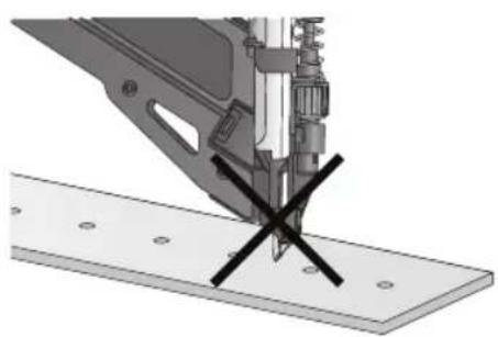
WARNING: Metal connector nails are not designed to penetrate metal. When installing metal connectors, ALWAYS place the hole locating tip into the metal connector's pre-formed hole, and orient so the nail is perpendicular to the hole before attempting to drive a fastener. Refer to Figure 9.
SEQUENTIAL MODE
The sequential mode is used for intermittent nailing. It offers the maximum battery life for driving nails.
- Using the mode selector switch (I), select the sequential mode (◀).
- Release the trigger safety lock-off (B).
- Place the hole locating tip (M) into the first hole on the metal connector and press down on the tool.
- Pull the trigger switch (A) to actuate the tool.
- Release the trigger and raise the nailer from the work surface.
- Repeat steps 3–5 to actuate the next nail.
RAPIDCYCLE SEQUENTIAL MODE
In RapidCycle sequential mode, the motor rotation speed is automatically restored after driving a nail to allow fast consecutive nailing, but with all of the health & safety benefits of a sequential actuating pattern. While offering the ability to drive more nails in less time, this mode more quickly depletes the battery charge.
- Use the mode selector switch (I) to select the RapidCycle sequential mode (◀◀).
- Release the trigger safety lock-off (B).
- Place the hole locating tip (M) into the first hole on the metal connector and press down on the tool.
- Pull the trigger switch (A) to actuate the tool.
- Release the trigger and raise the nailer from the work surface.
NOTE: The tool motor returns to full speed automatically without the contact tip (C) being depressed.
- Repeat steps 3–5 to actuate the next nail.
LED Indicator (Fig. 1)
Your nailer is equipped with two LED indicator lights (E) located on the back of the tool just below the back cap. Also refer to the Troubleshooting Guide for further instruction.
| [TY33] |  | LOW BATTERYReplace battery with a charged pack. |
 |  | HOT PACKLet the battery cool or replace it with a cool pack. |
| [KZTO] |  | JAM/STALL CONDITIONRotate the stall release lever to release. Refer to Stall Release. |
| [ABWO] |  | HOT TOOLLet the tool cool down before continuing use. |
 |  or any other combination. or any other combination. | ERRORReset tool by removing and reinserting battery pack or cycling trigger lock off. If error code persist, take tool to an authorized DEWALT service center. |
LOW BATTERY
HOT PACK
JAM/STALL CONDITION
HOT TOOL
ERROR
Stall Release (Fig. 1, 3)
If the nailer is used in rigorous application where all available energy in the motor is used to drive a fastener, the tool may stall. The driver blade did not complete the drive cycle and the jam/stall indicator (E) will flash. Rotate the stall release lever (F) on the tool and the mechanism will release. If the driver blade does not automatically return to the home position, proceed to Clearing a Jammed
Nail. If the unit continues to stall please review the mode selection, material and fastener length to be sure that it is not too rigorous an application.
DCN693
If continuous stalling occurs, review speed selection. Depending upon the application, a different speed setting may be necessary.
Clearing a Jammed Nail (Fig. 1, 3)

WARNING: Always engage the trigger safety lock-off (B) and disconnect battery pack and unload fasteners before attempting to clear a jam.
If a nail becomes jammed in the nosepiece, the jam/stall indicator light (E) will flash.

CAUTION: When removing a jammed nail, DO NOT orient the nailer with the nose up or with the battery foot up. Positioning the nailer this way makes the jammed nail or pieces of the nail more
likely to be ingested into the nailer. If any portion of a nail is ingested into the tool, the nail should be retrieved by removing the top cap.
NOTE: The jam could be as a result of debris build up in the nose channel. Please check and clear out any debris as outlined below immediately if you notice any change of performance in the tool.
- Remove battery pack from tool and engage trigger safety lock-off (B).
- After laying the tool on its side, slide the spring-loaded pusher latch (H) to the base of the magazine to lock it into place and unload nail strip.
NOTE: If nails don't release press nail support lever (N).
- Using the hex tool (K) provided, loosen the two hex bolts (Q) at the top of the magazine.
- Rotate the magazine (G) forward.
- Remove jammed/bent nail, using pliers if necessary. Clear out any debris in the nail channel if required.

CAUTION: If any portion of a nail is ingested into the tool, the nail should be retrieved by removing the top cap. Refer to Figure 11 a, b, d, e.
- If driver blade is in the down position, rotate the stall release lever (F) on the top of the nailer.
NOTE: If the driver blade will not reset after rotating the stall release lever, manually resetting the blade with a long screwdriver may be necessary.
- Rotate the magazine back into position under the nose of the tool and tighten hex bolts (Q).
- Reinsert battery pack.
NOTE: The tool will disable itself and not reset until the battery pack has been removed and reinserted.
- Reinsert nails into magazine (refer to Loading the Tool).
- Release the pusher latch (H).
- Disengage the trigger safety lock-off (B) when ready to continue nailing.
If nails become jammed in the nosepiece frequently, have the tool serviced by an authorised DEWALT service centre.
MAINTENANCE
Your DEWALT power tool has been designed to operate over a long period of time with a minimum of maintenance. Continuous satisfactory operation depends upon proper tool care and regular cleaning.

IG: To reduce the risk of serious personal injury, turn tool off and disconnect battery pack before making any adjustments or removing/installing attachments or accessories. An accidental start-up can cause injury.
The charger and battery pack are not serviceable.

Lubrication
Your power tool requires no additional lubrication.
NOTICE: NEVER spray or in any other way apply lubricants or cleaning solvents inside the tool. This can seriously affect the life and performance of the tool.

Cleaning

WARNING: Blow dirt and dust out of the main housing with dry air as often as dirt is seen collecting in and around the air vents. Wear approved eye protection and approved dust mask when performing this procedure.

WARNING: Never use solvents or other harsh chemicals for cleaning the non-metallic parts of the tool. These chemicals may weaken the materials used in these parts. Use a cloth dampened only with water and mild soap. Never let any liquid get inside the tool; never immerse any part of the tool into a liquid.
CHARGER CLEANING INSTRUCTIONS

G: Shock hazard. Disconnect the charger from the AC outlet before cleaning. Dirt and grease may be removed from the exterior of the charger using a cloth or soft non-metallic brush. Do not use water or any cleaning solutions.
Optional Accessories

WARNING: Since accessories, other than those offered by DEWALT have not been tested with this product, use of such accessories with this tool could be hazardous. To reduce the risk of injury, only DEWALT recommended accessories should be used with this product.
Consult your dealer for further information on the appropriate accessories.
DCN6931-XJ TIP REPLACEMENT (FIG. 10)
Over time the hole locating tip (M) will wear and eventually need replacement.

For your own safety, read the tool instruction manual before using any accessory. Failure to heed these warnings may result in personal injury and serious damage to the tool and the accessory. When servicing this tool, use only identical replacement parts.
TO REPLACE HOLE LOCATING TIP:
- Using a flathead screwdriver, gently push the hard rubber washer (S) off of the tip securing pin (T).
- Slide the pin (T) out of the nailer nose.
- Pull the worn/damaged tip out of the nose.
- Insert a new hole locating tip.
- Insert the new securing pin (T) through the nose and hole locating tip.
- Press the new hard rubber washer (S) back on to the securing pin.
NOTE: Only use new pin and grommet included with DCN6931 kit. The rubber grommet should not be reused.
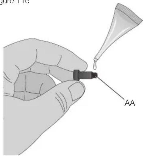
DCN6901 RETURN SPRING REPLACEMENT KIT (FIG. 11A-11E)
Over time - driver blade return springs will wear and eventually need replacement. It will become apparent that the springs will need replacement when the driver blade does not return home after every shot. To verify - open the magazine as in the
Clearing a Jammed Nail section and if the springs have worn out you will be able to move the driver backwards and forwards in the nail channel with very little resistance.
The tool has been designed in a way that it is easily possible for the return springs to be replaced in less than 5 minutes on site using accessory DCN6901-XJ.

For your own safety, read the tool instruction manual before using any accessory. Failure to heed these
warnings may result in personal injury and serious damage to the tool and the accessory. When servicing this tool, use only identical replacement parts.
NOTICE: All the mechanical parts of the spring replacement kit are shown for convenience and verification of inclusion. The kit also contains a packet of Loctite adhesive for use in step 9. Refer to Figure 11e.
TO CHANGE BROKEN RETURN SPRINGS:
NOTE: Springs should be replaced as a pair, using only the correct DEWALTaccessory spring replacement kit.
- Using the key (K) provided, loosen the two screws (AA) on either side of the unit. Refer to Figure 11a.
- Remove the return system (BB) from the unit. Refer to Figure 11b.
- Slide the spring rail clip (CC) off of the spring rail (DD). Refer to Figure 11c.
- Twist and remove the spring bumper (EE) and remove the washer (FF) and return spring (GG). Refer to figure 11c.
- Mount the new return spring and washer on to the spring rail (DD). While compressing the spring with the washer near the opposite end of the rail, twist on the new spring bumper until it is past the groove (HH) for the spring rail clip.
- Mount the new spring rail clip securely and position the bumper against the clip.
- Repeat steps 3–6 for the second spring.
NOTE: Check the return of the profile by sliding the profile up the spring rail and letting it go. It should return due to the force from the springs.
- Slide the return system (BB) back into the unit. Refer to figure 11d. It is important to try the alignment of the profile and the flywheel before screwing the return system back on to the unit. This can be done by connecting a battery and pushing then releasing the nose of the unit against a bench or hard surface. This will start the motor spinning.
NOTE: When the profile and the flywheel are correctly aligned, you will hear the motor coast back down from full speed. If the profile and the flywheel are not correctly aligned the motor it may not start up, may slow down much faster than normal along with a loud grinding noise from the unit. If this happens remove and reseat the return system.
ENGLISH
- Once the return system is correctly seated, open the provided sachet of Loctite ^®* and apply a small amount on the thread of the two screws (AA) and remount the two screws using the key and tighten securely. Refer to figure 11e.

:Always test the unit by driving short nails in to soft wood, to ensure that the tool is working properly. If tool does not operate properly, contact a recognized DEWALT service center immediately.

- CLOCTITE CONTENTS MAY IRRITATE EYES, SKIN, AND RESPIRATORY SYETEM. USE ENTIRE CONTENTS ON OPENING. Do not breath fumes. Do not get in eyes or on skin or clothing. Use only in a well ventilated area. Keep out of reach of children.
FIRST AID TREATMENT: Contains polyglycol dimethacrylate, polyglycol oleate propylene glycol, titanium dioxide, and cumene hydroperoxide. If swallowed, call a Poison Control Center or doctor immediately. Do not induce vomiting. If breathed in move person to fresh air. If in eyes, rinse with water for 15 minutes. Obtain medical attention. If on skin, rinse well with water. If on clothes, remove clothes.
*Loctite® is a registered trademark of Henkel Corp.
Protecting the Environment
Separate collection. Products and batteries marked with this symbol must not be disposed of with normal household waste.
Products and batteries contain materials that can be recovered or recycled reducing the demand for raw materials. Please recycle electrical products and batteries according to local provisions. Further information is available at www.2helpU.com.
Rechargeable Battery Pack
This long life battery pack must be recharged when it fails to produce sufficient power on jobs which were easily done before. At the end of its technical life, discard it with due care for our environment:
- Run the battery pack down completely, then remove it from the tool.
- Lithium-ion cells are recyclable. Take them to your dealer or a local recycling station. The collected battery packs will be recycled or disposed of properly.
TROUBLESHOOTING GUIDE
MANY COMMON PROBLEMS CAN BE SOLVED EASILY BY UTILIZING THE CHART BELOW.
For more serious or persistent problems, contact your nearest authorised DEWALT repair agent, or contact your DEWALT office at the address indicated in this manual.

WARNING: To reduce the risk of serious personal injury, ALWAYS lock off the tool and disconnect battery pack from tool before all repairs
| SYMPTOM CAUSE FIX | ||
| Motor does not run with contact trip depressed | Trigger lock in locked position Unlock trigger lock. | |
| Dry drive lock out engaged, blocking contact trip from traveling fully | Load more nails into magazine. | |
| Tool is stalled, locking the motor from rotating | Rotate the stall release lever on the tool and the mechanism will release. If driver blade does not return, remove battery and manually push driver blade back to home position. | |
| Bent contact trip See authorised | DEWALTrepair agent. | |
| Motor stops running after 5 seconds Normal operation, release contact trip and redepress. | ||
| Terminals are dirty or damaged See authorised | DEWALTrepair agent. | |
| Damaged internal electronics See authorised | DEWALTrepair agent. | |
| Damaged trigger See authorised | DEWALTrepair agent. | |
| Battery is hot Let the battery cool or replace it with a cool pack. | ||
| Tool is hot Let the tool cool down before continuing use. | ||
| Tool does not actuate (motor runs but will not drive a nail) | Dry drive lock out engaged, blocking contact trip from traveling fully | Load nails into magazine. |
| Low battery charge or damaged battery Check charge level if pack shows state-of-charge. Charge or replace battery pack if necessary. | ||
| Jammed nail/drive blade not returned to home position | Remove battery, clear jammed nail, cycle stall release lever, (push driver blade up manually if necessary) reinsert battery pack. | |
| Damaged driver/return assembly See authorised | DEWALTrepair agent. | |
| Jammed internal mechanism | See authorised DEWALTrepair agent. | |
| Damaged internal electronics See authorised | DEWALTrepair agent. | |
| Motor starts up but generates a lot of noise | Jammed nail and driver blade is stuck in down position | Use stall release lever, clear any jammed nails, and return driver blade manually if necessary. |
| Damaged driver/return assembly See authorised | DEWALTrepair agent. | |
| Drive blade continues to get stuck in down position | Jammed nail and driver blade is stuck in down position | Use stall release lever, clear and jammed nails, and return driver blade manually if necessary. |
| Damaged driver/return assembly See authorised | DEWALTrepair agent. | |
| Material and fastener length | If the unit continues to stall (forcing the need to rotate the Stall release lever) choose the appropriate material and fastener length that is not too rigorous an application. | |
| Debris in nosepiece | Clean nose area and watch closely for small pieces of broken nails stuck in the track. | |
| Tool is not yet run-in | New tools can take 500–1000 nails for parts to mesh and wear in together. Drive shorter nails during this period if experiencing difficulty driving nails flush. | |
| Use of incorrect speed (DCN693 only) | If trying to drive longer ring shank nails in soft woods, or driving ring shank nails into harder materials in speed 1 - adjust speed setting to position 2. | |
ENGLISH
| SYMPTOM CAUSE FIX | |||
| Tool operates but does not drive fasteners fully | Depth adjust set too shallow Rotate depth | adjust to a deeper setting. | |
| Tool not firmly applied to workpiece Apply | adequate force to tool securing it tightly to workpiece. Refer to instruction manual. | ||
| Material and fastener length If the unit continues to stall (forcing the need to rotate the Stall release lever) choose the appropriate material and fastener length that is not too rigorous of an application. | |||
| Damaged or worn driver blade tip Replace driver/return assembly. See authorised DEWALTrepair agent. | |||
| Damaged actuation mechanism See authorised DEWALTrepair agent. | |||
| Tool is not yet run-in New tools can take 500-1000 nails for parts to mesh and wear in together. Drive shorter nails during this period if experiencing difficulty driving nails flush. | |||
| Use of incorrect speed (DCN693 only) | If trying to drive longer ring shank nails in soft woods, or driving ring shank nails into harder materials in speed 1 - adjust speed setting to position 2. | ||
| Tool operates, but no fastener is driven | No nails in magazine Load nails in magazine. | ||
| Wrong size or angle nails Use only the recommended nails. Refer to Technical Data. | |||
| Debris in nosepiece Clean nose area and watch closely for small pieces of broken nails stuck in the track. | |||
| Debris in magazine Clean magazine. | |||
| Worn magazine | Replace magazine. See authorised DEWALTrepair agent. | ||
| Damaged or worn driver blade | See authorised DEWALTrepair agent. | ||
| Damaged pusher spring | Replace spring; see authorised DEWALTrepair agent. | ||
| Jammed nail | Wrong size or angle nails Use only the recommended nails. Refer to Technical Data. | ||
| Magazine screws not secured after previous jam clear/inspection | Make sure to tighten magazine hex bolts with wrench provided. | ||
| Damaged or worn driver blade | Replace driver blade. See authorised DEWALT repair agent. | ||
| Material and fastener length If the unit continues to stall (forcing the need to rotate the Stall release lever) choose the appropriate material and fastener length that is not too rigorous an application. | |||
| Debris in nosepiece Clean nose area and watch closely for small pieces of broken nails stuck in the track. | |||
| Worn magazine | Replace magazine. See authorised DEWALTrepair agent. | ||
| Dry drive lock out is engaged with only 7-9 nails remaining in magazine and the user is applying excessive force to contact trip, overriding the lockout | Load more nails in magazine to disengage dry drive lockout. | ||
| Tool is not yet run-in New tools can take 500-1000 nails for parts to mesh and wear in together. Drive shorter nails during this period if experiencing difficulty driving nails flush. | |||
| Use of incorrect speed (DCN693 only) | If trying to drive longer ring shank nails in soft woods, or driving ring shank nails into harder materials in speed 1 - adjust speed setting to position 2. | ||
| Poor driving hole performance | Damaged or worn hole locating tip | Replace tip with kit. If poor performace remains take tool to an authorised DEWALTrepair agent. | |
CLAVADORA INALÁMBRICA DE CONECTORES METÁLICOS DCN693, DCN694
¡Enhorabuena!
Suspension de charge.

Batterie rechargeable
BEWAAR ALLE WAARSCHUWINGEN EN INSTRUCTIES ALS TOEKOMSTIG REFERENTIEMATERIAAL
1) SIKKERHET PÅ ARBEIDSOMRÅDET
FOR Å SKIFTE UT HULLFINNERTUPP:
- Bruk en flat skrutrekker og skyv forsiktig den harde gummiskiven (S) av tuppens festepinne (T).
- Skyv pinnen (T) ut av nesen på spikerpistolen.
- Trekk den slitte/skadede tuppen ut av nesen.
- Sett inn en ny tupp.
- Sett inn den nye festepinnen (T) gjennom nesen og hullfinnertuppen.
- Trykk den nye harde gummiskiven (S) tilbake på festepinnen.
Director de Engenharia
D-65510, Idstein, Germany
16.11.2015