CSDXB32USB - Battery charger Tripp Lite - Free user manual and instructions
Find the device manual for free CSDXB32USB Tripp Lite in PDF.
| Product Type | 32-port USB Charging Station / Battery Charger |
| Brand | Tripp Lite |
| Model | CSDXB32USB |
| Dimensions (H x W x D) | 374 x 600 x 483 mm |
| Weight | 28.2 kg |
| Maximum Load Capacity | 81.65 kg |
| Input Power | 230 V, 5 A, 50 Hz |
| Output Power | 5.0 V, 2.4 A max per USB port |
| USB Ports | 32 x USB Type-A (female), 1 x USB Type-B (female), 2 x USB Mini (female) |
| Transmission Speed | USB 2.0 up to 480 Mbits/s |
| Operating Temperature | 0 °C to 30 °C |
| Operating Humidity | 5 % to 95 % (non-condensing) |
| Housing Material | Metal |
| Main Features | Charging and syncing of up to 32 smartphones, Apple compatible (iTunes, Apple Configurator), firmware update via mini-USB port |
| Mounting | Wall or desk mount (mounting hardware not included) |
| Security | Lockable doors with keys, optional padlock hasp, mandatory grounding |
| Maintenance and Cleaning | Unplug before cleaning, use a clean, damp, lint-free cloth, do not use solvents or abrasives |
| Warranty | 2-year limited warranty |
| Repairability | Tripp Lite Technical Support (tripplite.com/support) |
| Package Contents | Charging station, power cord (BS 1363 plug for CSDXB32USB), keys, padlock hasp, mounting screws |
Frequently Asked Questions - CSDXB32USB Tripp Lite
User questions about CSDXB32USB Tripp Lite
0 question about this device. Answer the ones you know or ask your own.
Ask a new question about this device
Download the instructions for your Battery charger in PDF format for free! Find your manual CSDXB32USB - Tripp Lite and take your electronic device back in hand. On this page are published all the documents necessary for the use of your device. CSDXB32USB by Tripp Lite.
USER MANUAL CSDXB32USB Tripp Lite
32-Port USB Charging Station for Smartphones
Models: CSD32USB, CSDXB32USB, CSDXS32USB
(Series number: AG-0737)
Table of Contents
- Important Safety Instructions 2
- Overview 3
- Feature Identification 4
- Setup 5
4.1 Powering the USB Charger/Hub Unit 5
4.2 Door Locks 5
- 32-Port USB Charger/Hub 6
5.1 USB Charger/Hub Features 6
5.2 Connecting Smartphones 6 to the USB Charger/Hub
5.3 Connecting a Computer to the 6 USB Charger/Hub
- Wall Mounting 7
- Desktop Placement 8
- Specifications 9
-
Storage, Service and Cleaning 10
-
Warranty and Product Registration 10
Español 11
Français 21
Русский 31
Deutsch 41
WARRANTY REGISTRATION
Register your product today and be automatically entered to win an ISOBAR ^® surge protector in our monthly drawing!
tripplite.com/warranty


TrippLite.Eaton.com/support
Copyright © 2023 Tripp Lite. All trademarks are the sole property of their respective owners.
1. Important Safety Instructions

SAVE THESE INSTRUCTIONS
This manual contains instructions and warnings that must be followed during the installation and operation of the product described in this manual. Failure to comply may invalidate the warranty and cause property damage or personal injury.
USB Charger/Hub Unit:
- Connect the unit to an outlet that is in accordance with your local building codes and adequately protected against excess current, short-circuits and earthly faults.
- The electrical outlet supplying power to the equipment should be installed near the unit and be easily accessible.
- The AC plug on the power supply cord serves as the disconnect device.
- Connect the unit directly to a properly grounded AC power outlet.
- Do not modify the plug, and do not use an adapter that would eliminate the ground connection.
• If any of the following situations arise, schedule an appointment with a service technician to have your equipment inspected:
• The equipment has been exposed to moisture
• The equipment has been dropped and damaged - The equipment shows obvious signs of breakage
- The equipment is not functioning properly or is not functioning according to the instructions described in this Owner's Manual
- Use of this equipment in life support applications where failure of this equipment can reasonably be expected to cause the failure of the life support equipment or to significantly affect its safety or effectiveness is not recommended.
Charging Station Cabinet:
- Keep the charging station in a controlled indoor environment away from moisture, temperature extremes, flammable liquids and gasses, conductive contaminants, dust and direct sunlight.
- Leave adequate space around the charging station for proper ventilation. Do not block, cover or insert objects into the charging station's external ventilation openings.
- For best performance, keep indoor temperature between 32^ and 86^ (0°C and 30°C).
- Do not remove any warnings, cautions or descriptive labels from the charging cart.
- The charging station is extremely heavy. Use caution when handling the charging station. Do not attempt to unpack or mount it unassisted. Use a mechanical device such as a forklift or pallet jack to move the charging station in the shipping container.
- Do not place containers of liquid or stack items on the cabinet.
- Inspect the shipping container and the charging station for shipping damage. Do not use the charging station if it is damaged.
- Use caution when cutting packing materials. The charging station could be scratched, causing damage not covered by the warranty.
- Save all packing materials for later use. Repacking and shipping the charging station cabinet or equipment without the original packing materials may cause product damage that will void the warranty.
For Wall-Mount and Desktop Installations:
- The charging station must be installed by a qualified technician.
- Before mounting, first make sure that the wall surface can safely support the combined load of the charging station, equipment stored and all attached hardware and components.
- The charging station can support equipment up to its maximum load capacity of 180 lb. (81.6 kg).
- Always use suitable mounting means when installing to cinder blocks, concrete, drywall or wood studs. Install securely to the wall using proper hardware (not provided).
WARNING: The supporting surface must be able to safely support the combined load of the charging station, equipment stored and all attached hardware and components (see 8. Specifications for more information on your model's weight and dimensions).
2. Overview
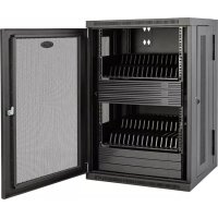
Your charging station is an all-in-one solution for storing, charging and syncing for up to 32 smartphones. Your charging station can be conveniently mounted to walls as well as used for stationary desktop installations. To prevent theft and device tampering, your charging station enclosure comes equipped with locking steel doors. A padlock hasp accessory (optional) attaches to the doors to provide an extra measure of protection.
Explanation of Symbols:

CAUTION: RISK OF DANGER

PROTECTIVE BONDING TERMINAL

AC VOLTAGE
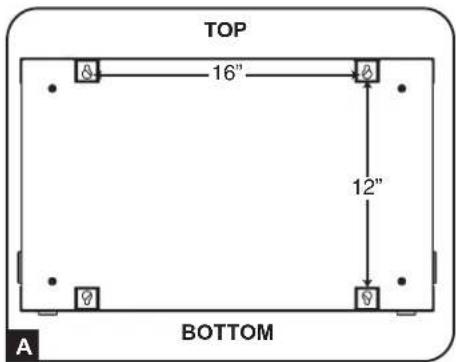
WALL-MOUNT WARNINGS: The wall surface, wall studs and all user-supplied mounting hardware must be able to support the combined weight of the cabinet and all equipment that will be installed in the cabinet. The cabinet can support equipment up to its maximum load capacity of 180 lb. (81.6 kg).
Wall-mounting holes are spaced 16 in. (406 mm) apart horizontally to accommodate standard placement of wall studs. It is advised to safety distribute the weight of the cabinet and all installed equipment.
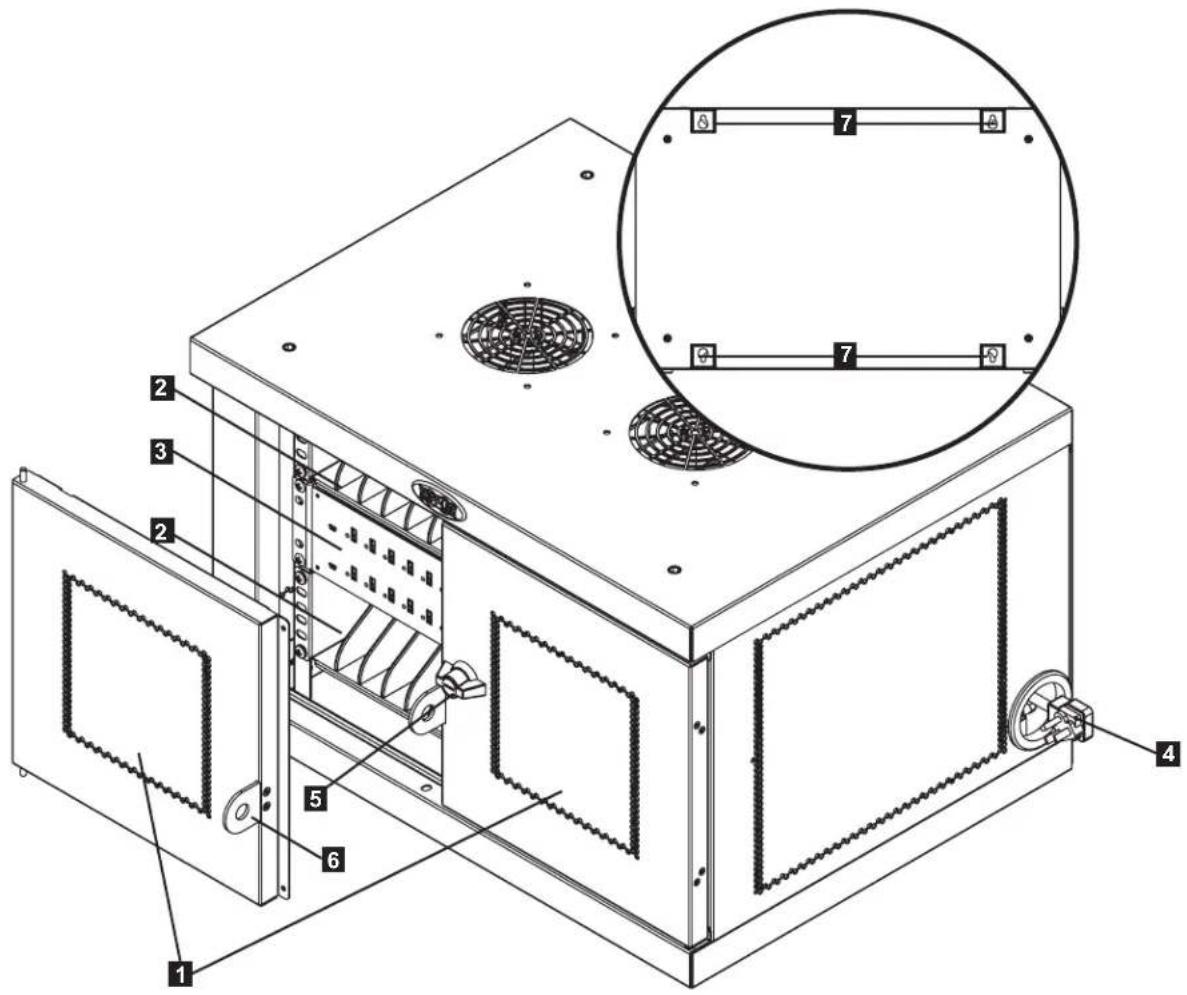
3. Feature Identification
CSD32USB
1 Locking Split Doors
2 Storage Shelves (Hold up to 16 Devices Each.)
3 32-Port USB Charger/Hub Unit
4 Power Cord Access Holes with 5-15P (CSD32USB) Right-Angle Plug (1 Opening Located on Each Side.)
5 3-Point Lock
6 Padlock Hasp (Optional. Assembly Required, See Section 3.4 for More Information. Lock Not Included.)
7 Rear Panel with Keyhole Wall Mount Slots (See Section 6 for More Information.)
Not Shown:
BS 1363 (CSDXB32USB) Plug or Schuko (CSDXS32USB) Power Cord Plugs
Keys
4. Setup

Caution! Read All Instructions and Warnings Before Installation!

Warning: Charging stations can be extremely heavy. Do not attempt to unpack or mount the charging station without assistance. Use extreme caution when handling the charging station and be sure to follow all handling and installation instructions. Do not attempt to install equipment without first stabilizing the charging station.
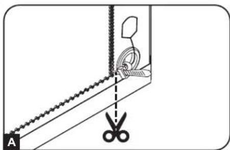
4.1 Powering the USB Charger/Hub Unit
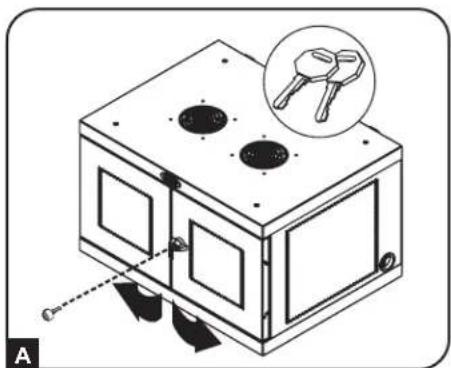
For convenient power connections, a tab is located on each side of the power cord access holes. To connect the USB charger/hub, choose which side you would like to use to plug in to a power outlet, then cut the zip ties securing both tabs to the power cord access holes A. Pull the tab from the desired power cord access hole B for the cord and plug to extend outward.
natural_image
Diagram showing a pair of scissors cutting through a metal frame with a wire and a clip, no text or symbols present.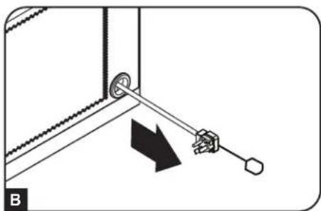
natural_image
Diagram of a mechanical linkage or lever mechanism with a black arrow indicating direction (no text or symbols present)4.2 Door Locks
The split doors contain a lock that is accessible with the included keys A.
The included padlock hasp accessory can attach to the unit to provide an extra measure of protection. To attach the padlock hasp, use the included screws to secure the hasp to the door B. Repeat for the other door.
natural_image
Diagram of a mechanical device with two circular holes and a magnified inset showing a key (no text or symbols present)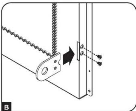
natural_image
Technical diagram showing a chain link attached to a metal bracket with an arrow indicating motion (no text or symbols present)5. 32-Port USB Charger Hub
5.1 USB Charger/Hub Features
• Professional-grade USB charger/hub charges and syncs up to 32 smartphones.
- Provides each USB port with an optimum charge level for a particular device (up to 2.4 amps).
- Allows syncing to be performed with any device designed for USB data communications, per compatible file management software.
- Syncs Apple ^® devices via iTunes ^® software or Apple Configurator.
- Mini-USB Firmware Upgrade Port enables future software upgrades to support newer devices.
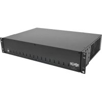
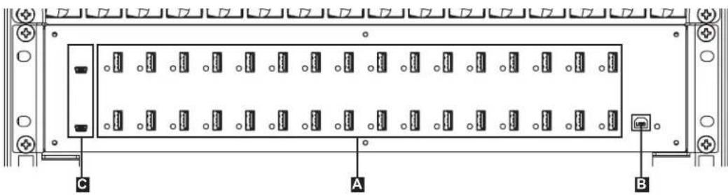
A 2.4A USB Device Ports with LED Indicator Lights (32 Total)
B Computer Sync Port
C Firmware Upgrade Ports
natural_image
Front view of a rack-mounted electronic device with labeled ports A, B, and C (no text or symbols beyond labels)5.2 Connecting Smartphones to the USB Charger/Hub
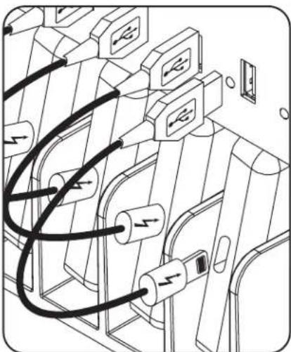
Using a user-supplied or device manufacturer's shielded USB cable, connect the USB cable to the smartphone to be charged. Repeat for all devices.
Tripp Lite offers individual and 10-pack cables for Apple devices using USB to 30-Pin or USB to Lightning™ cables, as well as individual and 10-pack cables for USB 3.0 or 2.0 devices using USB-A (male) to 5-Pin Micro B (male) cables.
| Cable Type | Individual Cable Model Number | 10-Pack Cable Model Number |
| Apple USB to 8-Pin Lightning Connector, 10 in. M100-10N-BK | M100-10N-BK-10 | |
| USB 3.0 SuperSpeed A (Male) to 5-Pin Micro-B (Male), 1 ft. U | 326-001-BK U326 | 001-BK-10 |
Visit tripplite.com for more information on our selection of premium USB cables.
natural_image
Diagram of electrical connectors with black cables and switches, no text or symbols present5.3 Connecting a Computer to the USB Charger/Hub
In addition to device charging, the USB Charger/Hub is equipped with a hub function that syncs devices and their respective software applications via a connected computer. To enable the hub function, use the included USB cable to connect the USB-B connector into the unit's Computer Sync Port and the USB-A connector into a computer's USB port.
Note: When a computer connection is established and multiple devices are connected to the USB Charger/Hub, the charge rate will reduce during syncing and resume to the normal charge rate upon completion.
Note: The Firmware Upgrade Port requires a mini-USB connection (cable not included). To download the most recent firmware updates, go to tripplite.com/support.
6. Wall Mounting
For wall mounting, you will need:
- Level
• Appropriate tools for wall mounting - Appropriate hardware for wall mounting (not included)
Warning: Do not attempt to mount the charging station to the wall with any personal electronic devices inside.
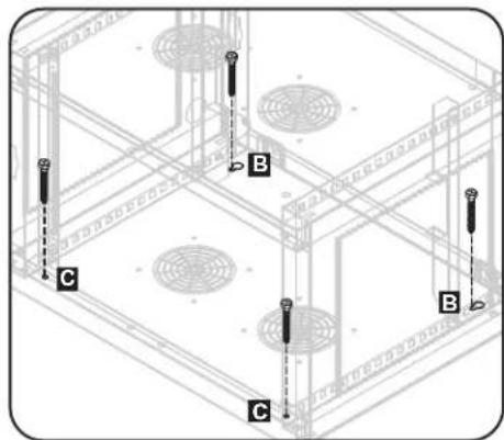
There are 4 keyhole cutouts on the charging station cabinet's rear panel. Each keyhole can accommodate an M5 or 3/16" bolt. The keyhole sets are centered 16" apart horizontally and 12" vertically A.
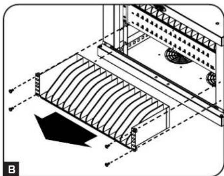
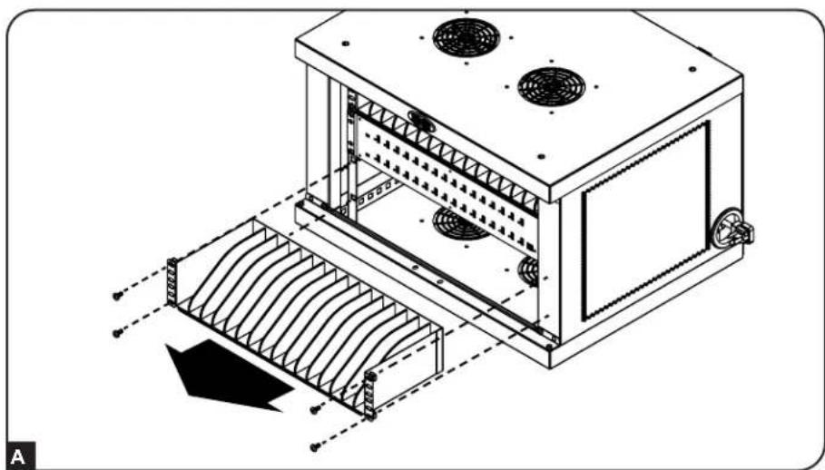
To mount the charging station, first remove the bottom shelf inside the cabinet B. Using a level and tape measure, measure to position your mounting area precisely. For the position where the top keyholes will be located, secure appropriate fasteners (not included) to the wall or supporting surface, then hang the charging station onto the hardware C. For an added measure of security, use appropriate fasteners and the bottom keyhole slots to secure the charging station cabinet to the wall D.
Note: The charging station must be installed by a qualified technician. Use suitable mounting means when installing to cinder block, concrete, drywall or wood studs. Warning: The supporting surface must be able to safely support the combined load of the charging station, equipment stored and all attached hardware and components. See Section 8. Specifications for more information on your model's weight and dimensions.
natural_image
Technical line drawing of a mechanical assembly with curved structural elements and mounting brackets (no text or symbols)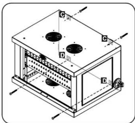
natural_image
Isometric technical diagram of a multi-compartment industrial or laboratory chamber with labeled components (no text or symbols present)7. Desktop Placement
WARNING: For desktop applications, always install the charging station in a structurally sound area with a level surface that is able to bear the weight of the charging station, all equipment that will be installed in the charging station and any other enclosures and/or equipment that will be installed nearby. Never attempt to lift or install the charging station without adequate help. See Section 8. Specifications for more information on the charging station's rated load capacity.
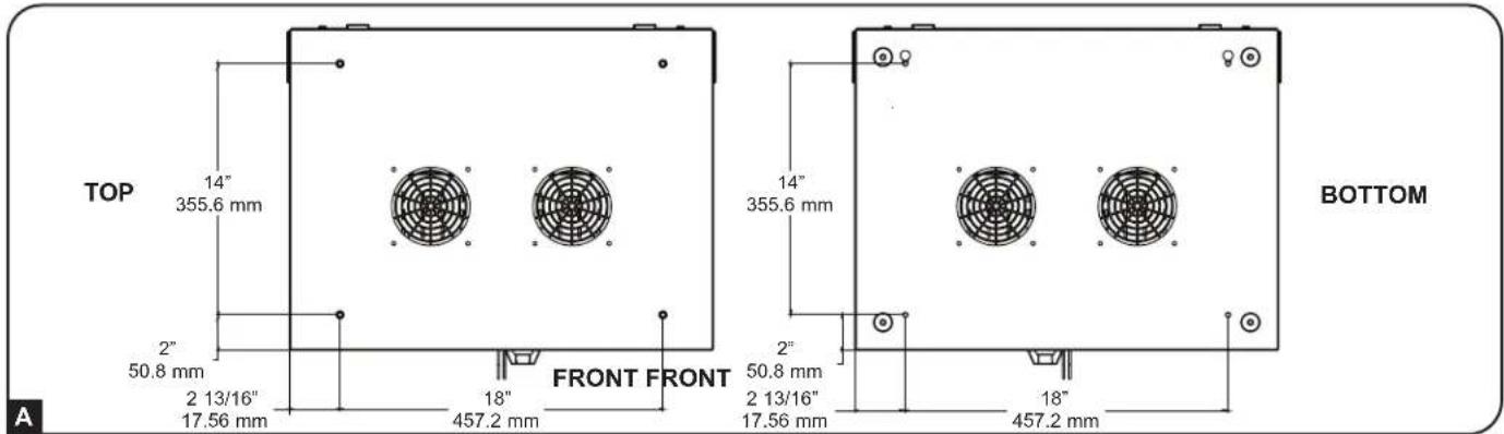
For an added measure of security, the cabinet can secure to a desktop. There are two keyhole cutouts located at the rear end of the bottom panel. Each keyhole can accommodate an M5 or 3/16" bolt. The bottom keyhole set is centered 18" (457 mm) apart horizontally and 14" (356 mm) vertically from the front mounting holes A.
Using a tape measure, measure to position your mounting areas precisely. Use appropriate fasteners (not included) to attach the cabinet to the rear keyhole cutouts B and secure the charging station to the desktop with the front mounting holes C.
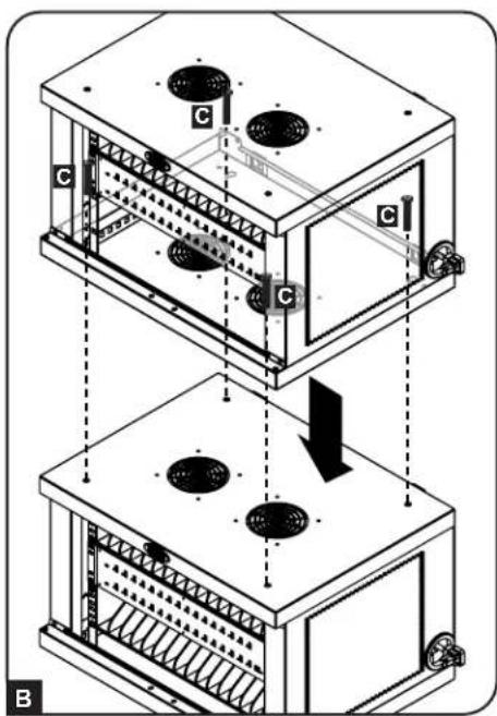
Stacking Charging Station Cabinets
One charging station can be securely stacked onto another. First remove the bottom shelf from inside the cabinet that will be placed on top A. Carefully place the top cabinet on top of the bottom cabinet, aligning the top cabinet's front mounting holes and rear keyhole cutouts with the bottom cabinet's threaded inserts located on the top panel B. To secure the two cabinets, use four (4) M6 x 20 mm screws (not included) C.
natural_image
Technical line drawing of a mechanical device with cooling fins and heat exchangers (no text or symbols)
Caution! Do not stack more than one Charging Station Cabinet. Personal or property damage may result.
8. Specifications
| Models CSD32USB, CSDXB32USB, CSDXS32USB | |
| Dimensions (H x W x D) 14.7 x 23.63 x 19 in. / 374 x 600 x 483 mm | |
| Unit Weight 62.11 lb. / 28.2 kg | |
| Load Capacity* 180 lb. / 81.65 kg | |
| Charger/Hub Ports 32 x USB Type-A (Female) | 1 x USB Type-B (Female)2 x USB Mini (Female) |
| Transmission Speed USB 2.0: Up to 480 Mbps | |
| Power Requirement Input: 110-120V, 8A, 50/60 | Hz (CSD32USB) or 230V, 5A, 50 Hz (CSDXB32USB, CSDXS32USB)Output: 5.0V, 2.4A Max (per USB port) |
| Operating Temperature 32° to 86° F / 0° to 30° | C |
| Operating Humidity 5 to 95% RH, Non-Condensing | |
| Enclosure Material Metal | |
*Full wall-mount load capacity requires a mounting surface capable of bearing the full load of the charging station and all connected components. Specifications may be subject to change without further notice.
9. Storage, Service and Cleaning
Storage
The enclosure should be stored in a controlled indoor environment away from moisture, temperature extremes, flammable liquids and gasses, conductive contaminants, dust and direct sunlight. Store the enclosure in its original shipping container if possible.
Service
The enclosure is covered by the limited warranty described in this manual. For more information, visit tripplite.com/support.
Cleaning
Before cleaning, always power off the charging station by unplugging it from its AC source. Dampen a clean, lint-free cloth with water and wipe down the unit, as necessary. Allow the surface area to dry before plugging in the unit.
Note: Avoid using abrasive cloths, solvents or aerosol sprays to clean the charging station; doing so can damage the unit.
10. Warranty and Product Registration
2-Year Limited Warranty
Seller warrants this product, if used in accordance with all applicable instructions, to be free from original defects in material and workmanship for a period of 2 years from the date of initial purchase. If the product should prove defective in material or workmanship within that period, Seller will repair or replace the product, at its sole discretion. THIS WARRANTY DOES NOT APPLY TO NORMAL WEAR OR TO DAMAGE RESULTING FROM ACCIDENT, MISUSE, ABUSE OR NEGLECT. SELLER MAKES NO EXPRESS WARRANTIES OTHER THAN THE WARRANTY EXPRESSLY SET FORTH HEREIN. EXCEPT TO THE EXTENT PROHIBITED BY APPLICABLE LAW, ALL IMPLIED WARRANTIES, INCLUDING ALL WARRANTIES OF MERCHANTABILITY OR FITNESS, ARE LIMITED IN DURATION TO THE WARRANTY PERIOD SET FORTH ABOVE; AND THIS WARRANTY EXPRESSLY EXCLUDES ALL INCIDENTAL AND CONSEQUENTIAL DAMAGES. (Some states do not allow limitations on how long an implied warranty lasts, and some states do not allow the exclusion or limitation of incidental or consequential damages, so the above limitations or exclusions may not apply to you. This warranty gives you specific legal rights, and you may have other rights which vary from jurisdiction to jurisdiction.)
WARNING: The individual user should take care to determine prior to use whether this device is suitable, adequate or safe for the use intended. Since individual applications are subject to great variation, the manufacturer makes no representation or warranty as to the suitability or fitness of these devices for any specific application.
Product Registration
Visit tripplite.com/warranty today to register your new Tripp Lite product. You'll be automatically entered into a drawing for a chance to win a FREE Tripp Lite product!*
* No purchase necessary. Void where prohibited. Some restrictions apply. See website for details.
Regulatory Compliance Identification Numbers
For the purpose of regulatory compliance certifications and identification, your Tripp Lite product has been assigned a unique series number. The series number can be found on the product nameplate label, along with all required approval markings and information. When requesting compliance information for this product, always refer to the series number. The series number should not be confused with the marketing name or model number of the product.
FCC Notice, Class B
This device complies with part 15 of the FCC Rules. Operation is subject to the following two conditions: (1) This device may not cause harmful interference, and (2) this device must accept any interference received, including interference that may cause undesired operation.
Note: This equipment has been tested and found to comply with the limits for a Class B digital device, pursuant to part 15 of the FCC Rules. These limits are designed to provide reasonable protection against harmful interference in a residential installation. This equipment generates, uses and can radiate radio frequency energy and, if not installed and used in accordance with the instructions, may cause harmful interference to radio communications. However, there is no guarantee that interference will not occur in a particular installation. If this equipment does cause harmful interference to radio or television reception, which can be determined by turning the equipment off and on, the user is encouraged to try to correct the interference by one or more of the following measures:
- Reorient or relocate the receiving antenna.
- Increase the separation between the equipment and receiver.
- Connect the equipment into an outlet on a circuit different from that to which the receiver is connected.
- Consult the dealer or an experienced radio/TV technician for help.
Any changes or modifications to this equipment not expressly approved by Tripp Lite could void the user's authority to operate this equipment.
WEEE Compliance Information for Tripp Lite Customers and Recyclers (European Union)

Under the Waste Electrical and Electronic Equipment (WEEE) Directive and implementing regulations, when customers buy new electrical and electronic equipment from Tripp Lite they are entitled to:
- Send old equipment for recycling on a one-for-one, like-for-like basis (this varies depending on the country)
- Send the new equipment back for recycling when this ultimately becomes waste
Tripp Lite has a policy of continuous improvement. Specifications are subject to change without notice. Photos and illustrations may differ slightly from actual products.

TrippLite.Eaton.com/support
natural_image
Diagram showing a rope being cut with scissors, no text or symbols present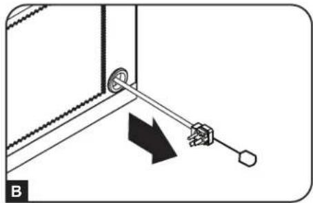
natural_image
Diagram of a mechanical assembly with a lever and pin, showing a directional arrow (no text or symbols)natural_image
Diagram of a mechanical device with two circular holes and a magnified inset showing a key inserted into one panel (no text or symbols present)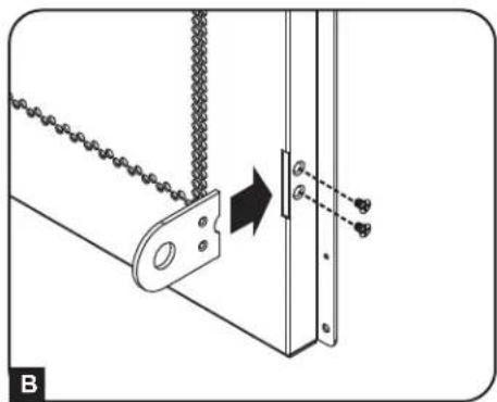
natural_image
Mechanical assembly diagram showing a chain link and mounting bracket with a directional arrow (no text or symbols)5. Cargador/Hub USB de 32 Puertos
natural_image
Diagram of electrical plug connections in a device (no text or symbols)natural_image
Technical line drawing of a mechanical assembly with curved structural elements and mounting brackets (no text or symbols)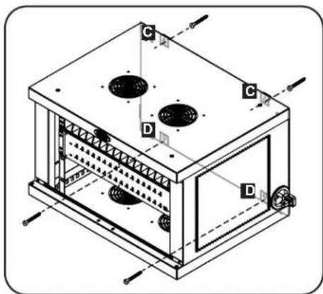
natural_image
Isometric technical diagram of a multi-compartment industrial or laboratory chamber with labeled components (no text or symbols present)natural_image
Isometric technical diagram of a structural frame with labeled components (A, B, C), no readable text or symbols present.natural_image
Technical line drawing of a mechanical or industrial device with cooling fins and ventilation grilles (no text or symbols)
8. Especificaciones
4. Configuration

natural_image
Diagram showing a sewing machine needle stitching a wall, with scissors cutting the edge (no text or symbols)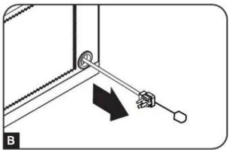
natural_image
Diagram showing a mechanical assembly with a lever and directional arrow (no text or symbols)natural_image
Diagram of a mechanical device with mounting holes and a close-up inset showing a tool (no text or symbols)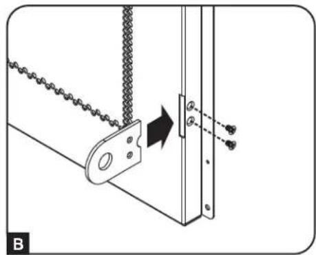
natural_image
Mechanical assembly diagram showing a chain connection with a bracket and mounting bracket (no text or symbols)natural_image
Front view of a rack-mounted electronic device with labeled ports A, B, and C (no text or symbols beyond labels)natural_image
Diagram of electrical connectors with black wires and switches, no text or symbols presentnatural_image
Technical line drawing of a mechanical assembly with curved structural elements and mounting brackets (no text or symbols)
natural_image
Technical line drawing of a mechanical device with cooling fins and heat exchangers (no text or symbols)
natural_image
Diagram showing a sewing machine needle with scissors and a pair of scissors (no text or symbols)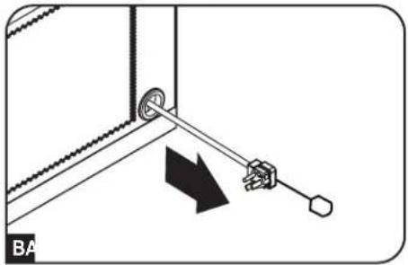
natural_image
Diagram showing a mechanical assembly with a lever and pin, no text or symbols present4.2 Дверные замки
natural_image
Diagram of a mechanical device with mounting holes and a close-up inset showing a tool (no text or symbols)
natural_image
Mechanical assembly diagram showing a chain hanging from a bracket with a vertical post and mounting holes (no text or symbols)natural_image
Front view of a rack-mounted server unit with multiple ports and connectors (no visible text or labels)natural_image
Diagram of electrical connectors with black wires and arrows indicating connections (no text or symbols)natural_image
Technical line drawing of a mechanical assembly with curved structural elements and mounting brackets (no text or symbols)
natural_image
Isometric technical diagram of a rectangular industrial or laboratory chamber with labeled components (C, D), no readable text or symbols present.natural_image
Isometric technical diagram of a structural frame with labeled points A, B, and C (no text or symbols beyond labels)natural_image
Technical line drawing of a mechanical device with cooling fins and ventilation grilles (no text or symbols)
natural_image
Diagram showing a pair of scissors cutting through a metal bracket with a wire and a clip, no text or symbols present.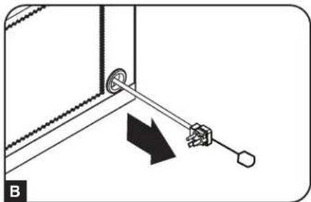
natural_image
Diagram of a mechanical assembly with a lever and pin, showing a directional arrow (no text or symbols)natural_image
Diagram of a mechanical device with labeled components and directional arrows, no readable text or symbols present.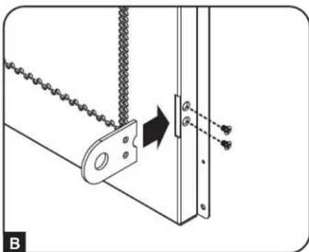
natural_image
Technical diagram showing a mechanical assembly with chains and a vertical component, no text or symbols presentnatural_image
Diagram of electrical connections with wires and switches (no text or symbols)natural_image
Technical line drawing of a mechanical assembly with curved structural elements and mounting brackets (no text or symbols)
natural_image
Isometric technical diagram of a rectangular industrial or laboratory chamber with internal components and labeled parts (no text or symbols present)natural_image
Technical line drawing of a mechanical device with cooling fins and heat exchangers (no text or symbols)