SU6KRT3UHWMB - Battery charger Tripp Lite - Free user manual and instructions
Find the device manual for free SU6KRT3UHWMB Tripp Lite in PDF.

| Product Type | Online double-conversion UPS (SmartOnline) |
| Brand | Tripp Lite |
| Model | SU6KRT3UHWMB |
| Output Capacity | 6 kVA / 5.4 kW (power factor 0.9) |
| Input Voltage | 200-240 V AC, single-phase, 30 A (L6-30P plug or hardwiring) |
| Output Voltage | 200 / 208 / 220 / 230 / 240 V AC (selectable) |
| Output Frequency | 50 / 60 Hz ±0.5 Hz (regulation or conversion) |
| Waveform Type | Pure sine wave |
| Internal Battery | Sealed lead-acid battery, hot-swappable, 2 battery modules |
| Typical Runtime | Approximately 5-10 minutes at full load (varies by load and battery age) |
| External Batteries | Up to 4 external Smart modules (BP192V12RT3US) |
| Dimensions (H x W x D) | 89 mm (2U) x 483 mm (19 inches) x 650 mm (approximate depth) |
| Approximate Weight | 55 kg (with internal batteries) |
| Mounting | 2U rack (2 or 4 post) or vertical tower (optional kit) |
| Main Features | Online double-conversion, interactive LCD screen, power strategies (auto-adaptive, max quality, max efficiency), frequency regulation/conversion, manual bypass, cold start, automatic restart |
| Communication | USB, RS-232, SNMP card slot, EPO, remote power on/off, Smart battery RJ-11 port |
| Safety | Protection against overloads, short circuits, overheating, emergency power off (EPO), FCC Class A compliance |
| Maintenance | Battery and fan replaceable by a qualified technician; firmware update via serial port |
| Spare Parts | Replacement battery cartridge (RBC58-3US), fans, power distribution modules (SUPDMB5HW, etc.) |
| Warranty | Standard manufacturer warranty (consult Tripp Lite for details) |
Frequently Asked Questions - SU6KRT3UHWMB Tripp Lite
User questions about SU6KRT3UHWMB Tripp Lite
0 question about this device. Answer the ones you know or ask your own.
Ask a new question about this device
Download the instructions for your Battery charger in PDF format for free! Find your manual SU6KRT3UHWMB - Tripp Lite and take your electronic device back in hand. On this page are published all the documents necessary for the use of your device. SU6KRT3UHWMB by Tripp Lite.
USER MANUAL SU6KRT3UHWMB Tripp Lite
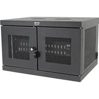
Single-Phase Rack-Mount Online UPS with Built-in LCD Monitoring, Control Screen and Detachable Bypass Power Distribution Module
Not suitable for mobile applications.
Product Bundle Configurations:
SU5KRT3UHVMB, SU5KRT3UHVMBP, SU5KRT3UGMB, SU5KRT3UHWMB, SU6KRT3UHVMB, SU6KRT3UHVMBP, SU6KRT3UGMB, SU6KRT3UHWMB, SU6KRT3UXMB
Models:
SUPDMB5, SUPDMB5P, SUPDMB6, SUPDMB6P SUPDMB6IEC, SUPDMB5G, SUPDMB6G, SUPDMB5HW, SUPDMB6HW
(Series Number: AG-03DD)
SU5KRT3PM, SU6KRT3PM
(Series Number: AG-0357)
Español 41 • Français 81 • Русский 121
NOTE: External battery pack options require configuration using front panel LCD interface or via Tripp Lite's EXTERNAL BATTERY CONFIGURATION software.
WARRANTY REGISTRATION
Register your product today and be automatically entered to win an ISOBAR ^® surge protector in our monthly drawing!
tripplite.com/warranty


text_image
TRIPP·LITE
1111 W. 35th Street, Chicago, IL 60609 USA • tripplite.com/support
Copyright © 2021 Tripp Lite. All rights reserved. SmartOnline ^10 is a trademark of Tripp Lite. For latest updates, please visit tripplite.com
Table of Contents
1. Overview 3
Parts List 3
Additional Accessory Options 3
2. Important Safety Instructions 3
3. UPS Circuit Block Diagram 6
4. Installation 7
Internal Battery Rotation 7
Rack Mounting 9
Tower Mounting 14
Hardwire Input and Output Wiring Instructions 15
(Optional with Select Models)
UPS Input and Output Overview 16
5. Features 17
Front Panel Controls, LEDs and LCD Screen 17
UPS Rear Panel 17
PDM Panel 18
6. Operations 19
LCD Front Panel Display and Controls 19
LED Front Panel Indicators 20
Front Panel Button Functions 21
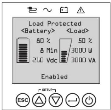
Home Screen Layout 21
Basic Connections and Start-Up 22
Power Strategy Selection Options 25
Front Panel LCD Selection and 27
Configuration Options
Configuring External Battery Packs 30
PDM Maintenance Bypass Procedure 31
Replacement UPS Power Module 31
Installation Procedure
7. Optional Connections 32
8. Troubleshooting and Event Log 35
9. Internal Battery Replacement 37
-
Fan Replacement 39
-
Storage and Service 40
-
Product Registration 40
Overview
Tripp Lite SmartOnline rack-mount UPS systems with interactive LCD interface feature on-line, double-conversion UPS protection with full-time sinewave output and zero transfer time, making them suitable for all advanced networking applications. The detachable Power Distribution Module (PDM) uses a blindmate connection, providing a seamless installation and allowing the UPS to be serviced or hot-swapped while keeping connected loads powered. Each UPS provides long running battery support with optional extended-run and Web communications ability. Built-in interfaces include Micro-USB, RS-232 serial, Emergency Power Off (EPO), Remote On/Off (ROO) and an RJ-11 smart battery port. The interactive front panel LCD screen provides detailed UPS status, preset and control options. Optional max efficiency and auto-adaptive power strategy options enable high-efficiency operation with reduced power consumption and BTU heat output.
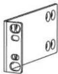
Parts List
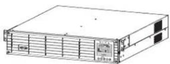
natural_image
Line drawing of a server rack unit with ventilation grilles and control panel (no text or symbols)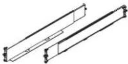
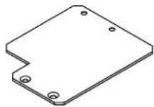
UPS System UPS 4-Post Rail Kit Tower Mounting Plate (2) Bypass PDM (Outlets and Outlet
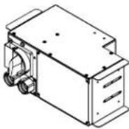
Configuration Vary by Model)
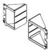
PDM Mounting
Brackets
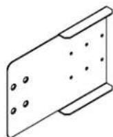
Deep Rack Extension Bracket (2)

M4 x 6 mm
Screw (8)

Thumbscrew (4) Bolt-on Mounting Ears (2)

Hardwire Strain Reliefs (2)
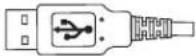
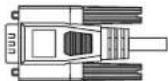
USB Cable (1) RS-232 Cable (1) (Select models) AC Input Power
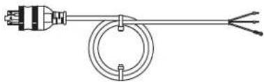
natural_image
Simple line drawing of a heating element with a bulb and three wires (no text or symbols)Cord with L6-30P Plug (1)
Owner's Manual
Optional Accessories (Not Included)
- 2POSTRMKITWM: Supports rack-mount UPS and battery packs in 2-post rack-mount or wall-mount configurations
• 2-9USTAND: Supports rack-mount UPS and battery packs in upright tower configuration - BP192V12RT3US External "SMART" Battery Pack: Extends the runtime of the UPS system

Important Safety Instructions
SAVE THESE INSTRUCTIONS
This manual contains important instructions and warnings that should be followed during the installation, operation, maintenance and storage of all Tripp Lite UPS Systems, Batteries and Detachable PDM. Failure to heed these warnings may affect your warranty.
Explanation of Symbols

Caution—risk of danger

Hot—overheating may occur

Electrical shock hazard

Protective earth ground

Bonding ground

Recyclable—contains lead
UPS Location Warnings
- Your UPS/PDM is intended to be used in a temperature-regulated, indoor area that is relatively free of conductive contaminants. Install your UPS/PDM indoors, away from excess moisture or heat, conductive contaminants, dust or direct sunlight.
- Ambient room temperature should be between 32^ and 104^ (0°C and 40°C).
- Leave adequate space around all sides of the UPS for proper ventilation.
- The PDM provides the convenience of multiple outlets, but DOES NOT provide surge or line noise protection for connected equipment, when in Bypass Mode.
- Do not mount unit with its front or rear panel blocked. Mounting in this manner will seriously inhibit the unit's internal cooling, eventually causing product damage not covered under warranty.
UPS Installation and Connection Warnings
All Models

CAUTION: Installation should be performed by qualified professional electrical service personnel only.
- Install in accordance with National Electrical Code standards. Be sure to use the proper overcurrent protection for the installation in accordance with the plug/equipment rating.
- Be sure to use an upstream circuit breaker with a C curve.
• Overcurrent protection shall be provided in the end-use application, installed in accordance with local and national electrical wiring regulations. - Short-circuit backup protection and overcurrent protection is provided by the building Installation, in the hardwire configuration (Bypass and Economy Modes).
• Install at a height not exceeding 1 m (3.3 ft.). - Equipment is intended for use on a TN-S power distribution system.
Select Models Come Equipped with an L6-30P Plug

CAUTION: To reduce the risk of fire, connect only to a circuit provided with 30A maximum branch circuit overcurrent protection in accordance with the National Electrical Code, ANSI/NFPA 70 and the Canadian Electrical Code, Part I, C22.1.
- The AC mains L6-30P plug serves as the disconnect device. The electrical outlets supplying power to the equipment must be installed near the equipment and easily accessible. Alternatively, a local disconnect may be provided.
- DO NOT use the hardwire AC supply input option when an L6-30P plug is present. Doing so may cause a catastrophic dangerous situation.
- When the hardwire AC output is used, appropriate output overcurrent protection must be provided.

Important Safety Instructions
Select Hardwire Models

CAUTION: To reduce the risk of fire, connect only to a circuit provided with maximum branch circuit overcurrent protection in accordance with the National Electrical Code, ANSI/NFPA 70 and the Canadian Electrical Code, Part I, C22.1. See "UPS Input and Output Overview" table in the Installation section for details.
- Use copper conductors with rated 105°C wires only. See “UPS Input and Output Overview” table in the Installation section for recommended input and output configuration.
- For models equipped with a permanent hardwire output connection, overcurrent protection is to be provided in the end use installation. Use output branch-rated overcurrent protection not exceeding the UPS Output rating. When supplying receptacles with lesser branch-rated overcurrent protection, the overcurrent protection should match the receptacle rating.
- In Europe, the circuit breaker must meet the IEC/ EN 60934 standard and have a contact air gap of at least 3 mm.
- When the hardwire AC output is used, appropriate OUTPUT OVERCURRENT protection must be provided by the installer. Be sure to use branch rated circuit breakers that match the rating of the receptacles/equipment being protected. Use circuit breaker(s) with a C curve.
- An appropriate and readily accessible two-pole disconnect device must be incorporated in the fixed wiring.
- In Europe, the AC mains connection is L, N, PE(GND). Make sure to hook up the L to the hot and N to the neutral conductor.
- Never attempt to install electrical equipment during a thunderstorm.
- Do not attempt to use this equipment if any part of it becomes damaged.
- Individual equipment connected to the UPS/PDM should not draw more current than the PDM outlet's rating.
- The total load connected to the UPS/PDM must not exceed the maximum load rating for the UPS/PDM.
- Do not attempt to modify the UPS/PDM, enclosure, input plugs or power cables.
- Do not attempt to use the UPS/PDM if any part of it becomes damaged.
Equipment Connection Warnings
- Do not connect surge protectors or extension cords to the output of your UPS. This may damage the UPS and may affect the surge protector and UPS warranties.
- The total load connected to the UPS must not exceed the maximum nameplate load rating.
- Use of this equipment in life support applications where failure of this equipment can reasonably be expected to cause the failure of the life support equipment or to significantly affect its safety or effectiveness is not recommended. Do not use this equipment within oxygen-enriched atmospheres, or within 0.3 m (1 ft.) of a point at which an oxygen-enriched atmosphere is intentionally vented
Fan Replacement Warning

Make sure UPS is powered down, i.e. turned off prior to fan replacement. Failure to do so may cause overheating and trigger thermal shutdown

CAUTION: The fan circuitry is not isolated from AC mains. Turn off power to the UPS prior to fan replacement. Fan replacement must be performed by qualified electrical service personnel.
Battery Warnings
- There are no user-serviceable parts inside the UPS.
- Battery rotation must be performed by qualified electrical service personnel.
- Battery replacement should be performed only by authorized service personnel.
- Servicing of batteries should be performed or supervised by personnel knowledgeable about batteries and the required precautions.
- When replacing batteries, replace with the same type and number of batteries or battery packs.
CAUTION: Do not dispose of batteries in a fire. The batteries may explode.
CAUTION: Do not open or mutilate batteries. Released electrolyte is harmful to the skin and eyes. It may be toxic.
CAUTION: A battery can present a risk of electrical shock and high short-circuit current. Contact with any part of a grounded battery can result in electrical shock. The following precautions should be observed when working on batteries:
- Remove watches, rings, or other metal objects.
- Use tools with insulated handles.
- Wear rubber gloves and boots.
- Do not lay tools or metal parts on top of batteries.

Important Safety Instructions
- Do not short or bridge the battery terminals with any object.
- Remove battery grounds during installation and maintenance to reduce likelihood of shock.
- Remove the connection from ground if any part of the battery is determined to be grounded.

External Battery Warnings
- Connect external battery ground wire before connecting external battery to UPS.
- For external battery configuration, see the Operations section for options and configuration method. Smart battery packs are automatically detected by the UPS.
- Fuses should be replaced only by factory authorized personnel. Replacement fuses should be of the same rating and type.
- For extended runtime, only use compatible Tripp Lite battery modules:
• BP192V12RT3US External Battery Pack
Battery Replacement and Recycling

Tripp Lite products use sealed lead-acid batteries, which are highly recyclable. Refer to your local codes for disposal requirements, Call Tripp Lite at +1.773.869.1234 or visit triplite.com/support/recycling-program for more information on recycling the batteries or any other Tripp Lite product.
Tripp Lite offers a complete line of UPS System Replacement Battery Cartridges (R.B.C.). Visit Tripp Lite on the Web at triplite.com/products/battery-finder/ to locate the specific replacement battery for your UPS.
Maintenance Warnings
- Your UPS does not contain user-serviceable parts. Do not disassemble.
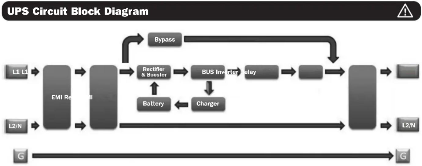
flowchart
graph LR
    L1_L1 --> EMI_Res["EMI Rectifier"]
    L2_N --> EMI_Res
    EMI_Res --> Rectifier["Rectifier & Booster"]
    Rectifier --> BUS_Bus["BUS Inverter Relay"]
    BUS_Bus --> Charger["Charger"]
    Bus_Bus --> Bypass["Bypass"]
    Bus_Bus --> L2_N
    Bus_Bus --> G["G"]
    Bypass --> Bus_Bus
    Battery <--> Battery
    Bus_Bus --> Bypass
Installation
Internal Battery Rotation
Your UPS ships with the batteries disconnected and in reverse orientation. Before mounting the UPS to your 4-post or 2-post rack, first remove the battery trays and set them aside. To remove the batteries from the UPS, follow the instructions below.
If an external battery pack is to be used, it should be installed first in the lower part of the rack. Be sure to follow instructions for Configuring External Battery Packs in this manual and in the BP192V12RT3US Owner's Manual before proceeding with UPS installation.
WARNING! Battery rotation must be performed by qualified electrical service personnel.
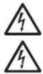
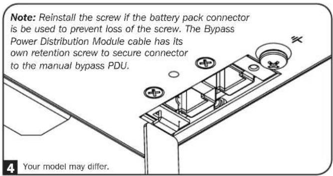
1 Remove the six front screws from the front bezel, then retract the bezel from the UPS. Hang the bezel on the available hook.
Note: The front panel display has an attached ribbon cable that extends from the UPS to the front bezel. Make sure to keep this cable out of the way when opening and closing the battery door.
natural_image
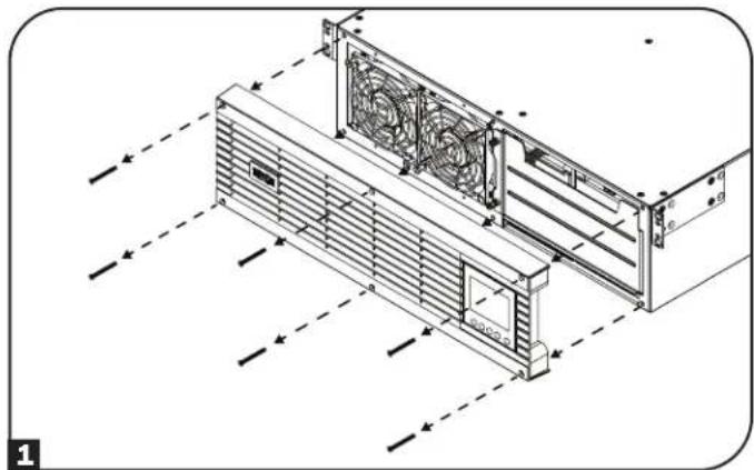
Technical line drawing of a server rack unit with fan blades and ventilation ducts (no text or symbols)2 Loosen the two captive screws securing the battery door.
natural_image
Technical line drawing of a server rack with fan blades and mounting holes (no text or symbols)3 Open the battery door. Ensure the smart battery communications cable is safely out of the way when opening the battery door and when removing the battery trays.

natural_image
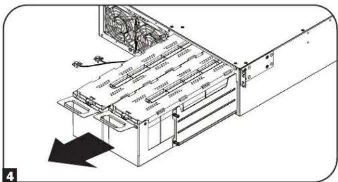
Diagram of a computer tower drive showing fan arrangement and cable routing (no text or symbols)4 Using the handles attached to each tray, remove the battery pack trays. Make sure to remove the handles before rotating the batteries (see next step) and install the handles on the opposite side.
natural_image
Diagram of a server rack with cooling fans and ventilation ducts, showing internal structure without any text or symbolsIt is recommended you remove the UPS internal batteries prior to installation. Doing so will remove excess weight and allow for safer handling.
Note: To reduce the weight of the UPS unit during installation, it is recommended you proceed to 4-Post Mounting or 2-Post Mounting instructions in the Rack Mounting section before rotating, reinstalling and connecting the battery pack trays.
Installation
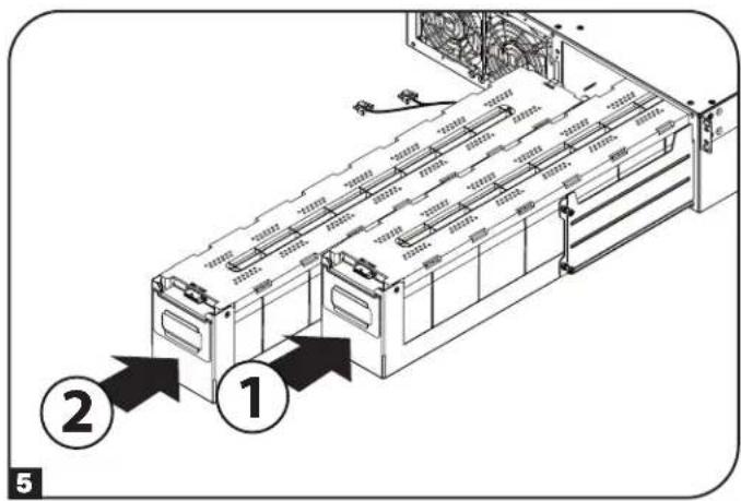
5 Each battery tray uses a blindmate DC connector. Position each battery tray so the red and black DC connector end is facing towards the rear of the UPS and the communication port is facing toward the front of the UPS. Starting with the right side battery tray, insert the battery tray, making sure it protrudes slightly from the UPS. Repeat for the left side battery tray.
Note: For better connector access, attach the cables before the battery packs are fully inserted into the UPS.
6 Connect the battery communication cable to each battery tray and push the battery trays completely into the UPS.
7 Close the battery door and secure by tightening the captive screws.
8 Reattach the front bezel to the UPS and secure with the screws removed in step 1.
text_image
Technical diagram of a server rack with numbered annotations pointing to components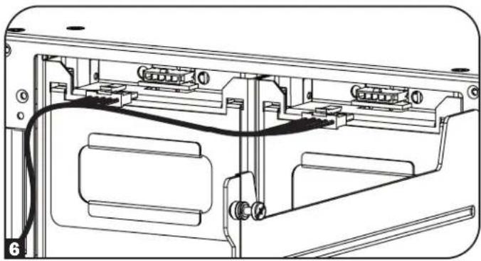
natural_image
Technical line drawing of a device rear panel with connectors and wiring (no text or symbols)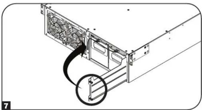
natural_image
Technical illustration of a computer tower drive with fan and cable (no text or symbols)
natural_image
Technical line drawing of a server rack unit with fan and ventilation ducts (no text or symbols)Installation
Rack Mounting
Mount your equipment in either a 4-post or 2-post rack or rack enclosure. The user must determine the fitness of hardware and procedures before mounting. If hardware and procedures are not suitable for your application, contact the manufacturer of your rack or rack enclosure. The procedures described in this manual are for common rack and rack enclosure types and may not be appropriate for all applications.
CAUTION: The equipment should be installed onto the rack rails at a height <1 m (36 in.).

If an external battery pack is to be used, it should be installed first in the lower part of the rack. Be sure to follow instructions for Configuring External Battery Packs in this manual and in the BP192V12RT3US Owner's Manual before proceeding with UPS installation.
4-Post Mounting
Mounting the UPS
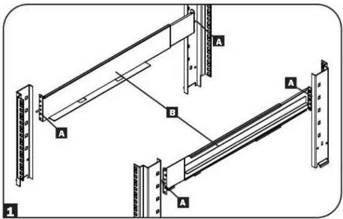
1 The included plastic pegs A will temporarily support the empty rack-mount shelves B while you install the permanent mounting hardware. Insert a peg into the third hole from the top on the front end of each bracket. On the rear end, insert a peg into the center hole. (Each front bracket has 6 holes and each rear bracket has 5 holes.) The pegs will snap into place.
After installing the pegs, expand each shelf to match the depth of your rack rails. The pegs will fit through the square holes in the rack rails to support the shelves. Refer to the rack unit labels to confirm that the shelves are level in all directions.
Note: The support ledge of each shelf must face inward.
2 Remove the pegs at the front end of each bracket. Secure the shelves B to the mounting rails permanently using the included screws and cup washers C as shown. Place 2 screws at the front of each rail (4 total) and 2 screws at the back of each rail (4 total). When securing to the rear rail, make sure each set of bracket screws are positioned above and below the lower screw used to secure the PDM Mounting Bracket D. Tighten all screws before proceeding.
Note: The rear pegs can be left in for installation, but the front ones must be removed before the bracket is secured by screws.
WARNING!
Do not attempt to install your UPS until you have inserted and tightened the required screws. The plastic pegs will not support the weight of your UPS.
text_image
A B A A A 1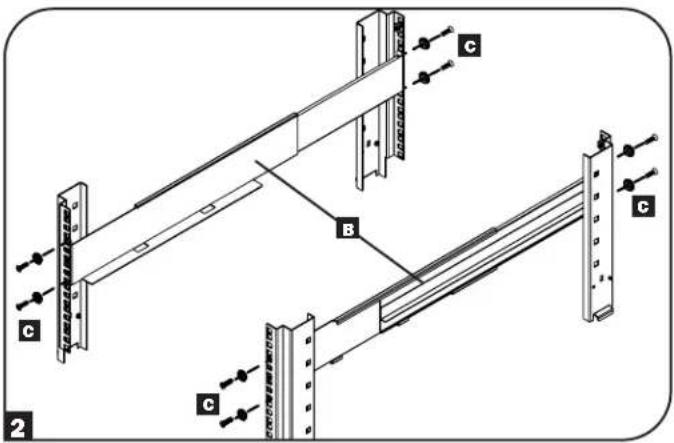
text_image
C B C C 2 CInstallation
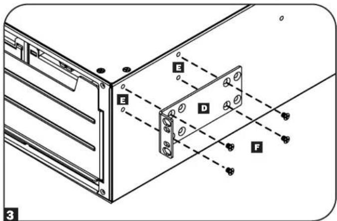
3 Attach your UPS mounting brackets D to the forward mounting holes E of the UPS using the included hardware F. The mounting bracket "ears" should face forward.
It is recommended you remove the UPS internal batteries prior to installation. Doing so will remove excess weight and allow for safer handling.
Note: To remove battery pack trays inside the UPS, refer to Internal Battery Rotation.
text_image
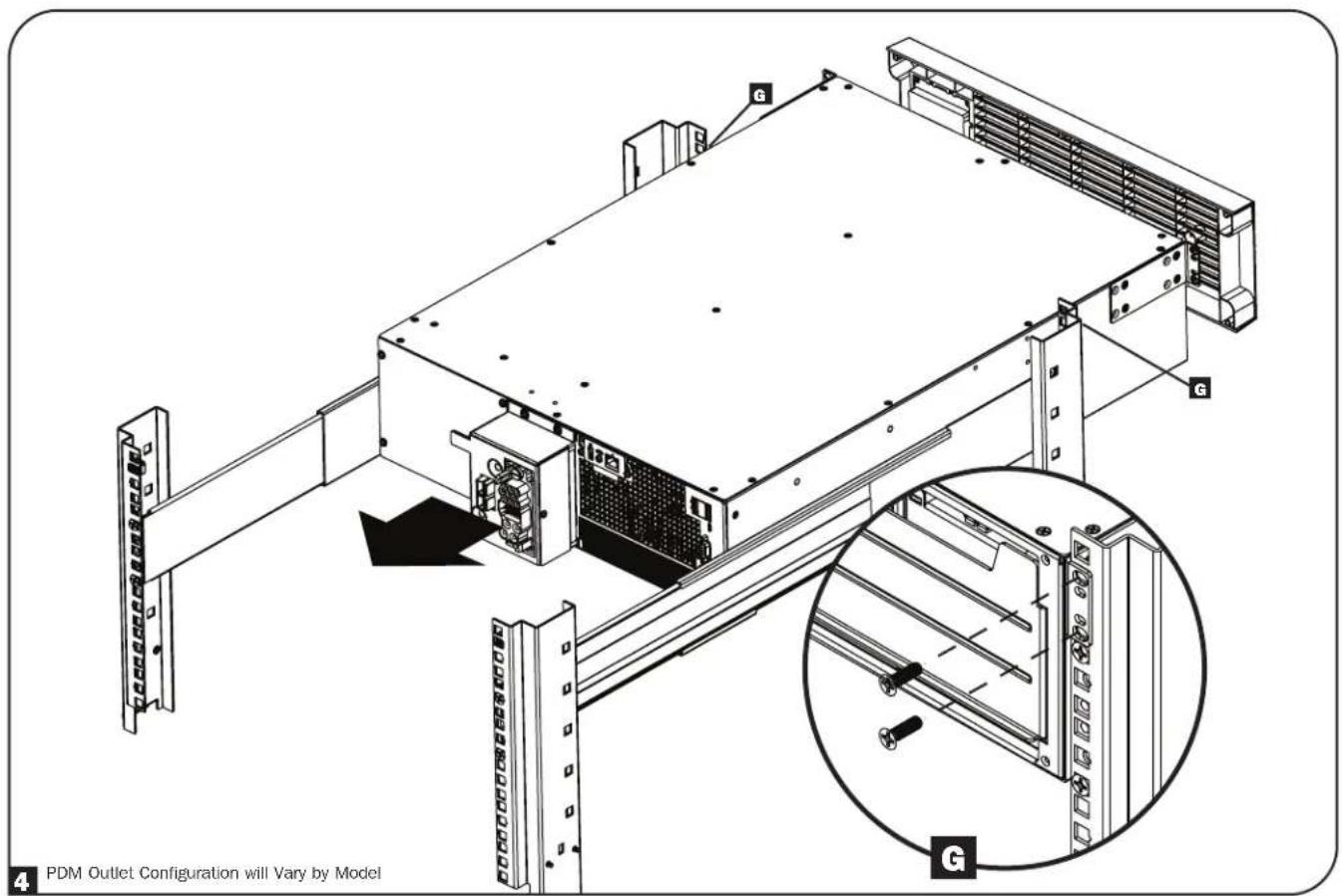
E E D F 34 With the aid of an assistant, lift your UPS and slide it into the shelves. Attach the UPS mounting ears to the front mounting rails with user-supplied screws and washers 6. Tighten all screws securely.
Note: To install battery trays inside the UPS, refer to instructions 5-8 in the Internal Battery Rotation section within the Installation section of this manual.
text_image
G G G 4 PDM Outlet Configuration will Vary by ModelInstallation
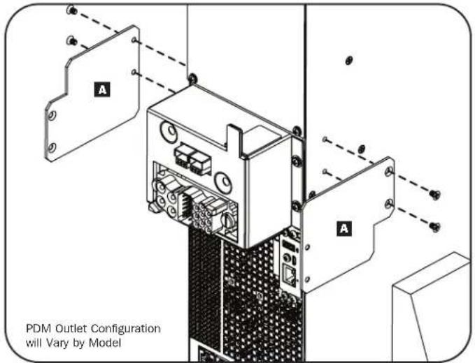
Mounting the Power Distribution Module in Standard-Depth Rack Enclosures
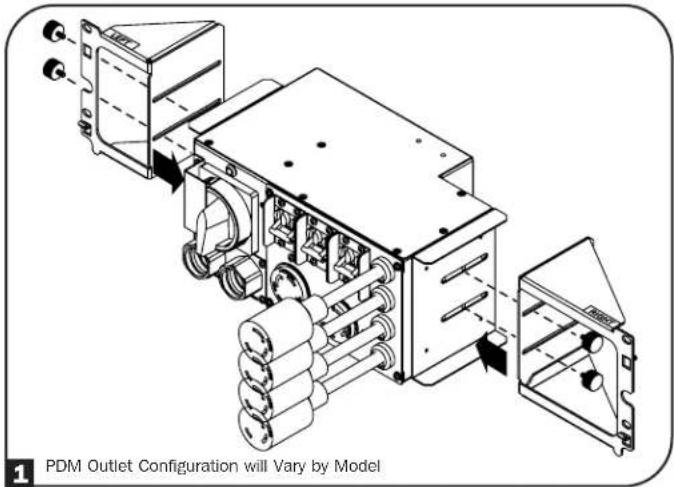
1 Using the thumbscrews, attach the PDM Mounting Brackets to the PDM. The default position to install the thumbscrews is in the center holes, as shown.
Notes:
- Do not fully tighten thumbscrews at this time.
- For extended runtime applications, attach and secure the external battery cable and ground wire to the underside of the Bypass Power Distribution Module battery connector and grounding screw.
text_image
1 PDM Outlet Configuration will Vary by ModelBypass Power Distribution Module Attachment Points – The tightening torque for the ground screw is 1 n·m (10 lb·in.).
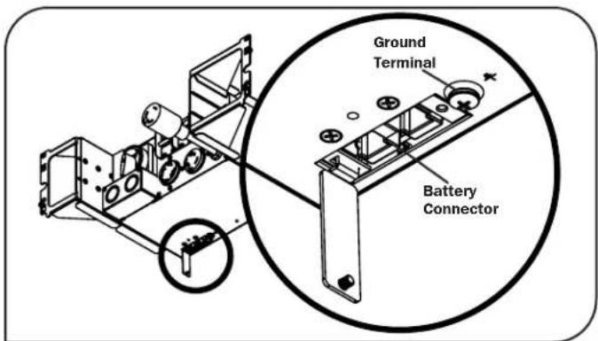
text_image
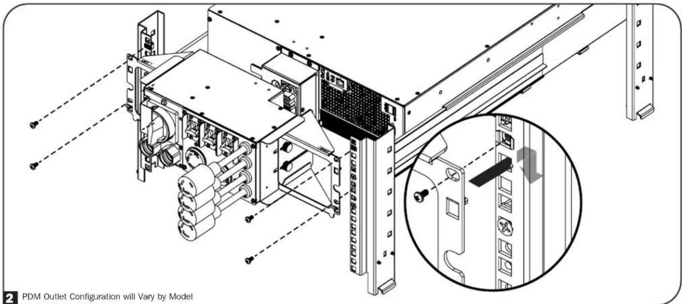
Ground Terminal Battery Connector2 Attach the PDM assembly to the rack's rear rails. The brackets' built-in hooks provide temporary support while securing the PDM to the rack with the permanent mounting hardware.
Note: PDM Mounting Brackets can be laterally adjusted to ensure a proper connection between the UPS and PDM. To adjust the brackets, loosen the thumbscrews. Fully extend the PDM to the end of the brackets. Do not tighten screws at this time. Refer to step 4 for more information.
text_image
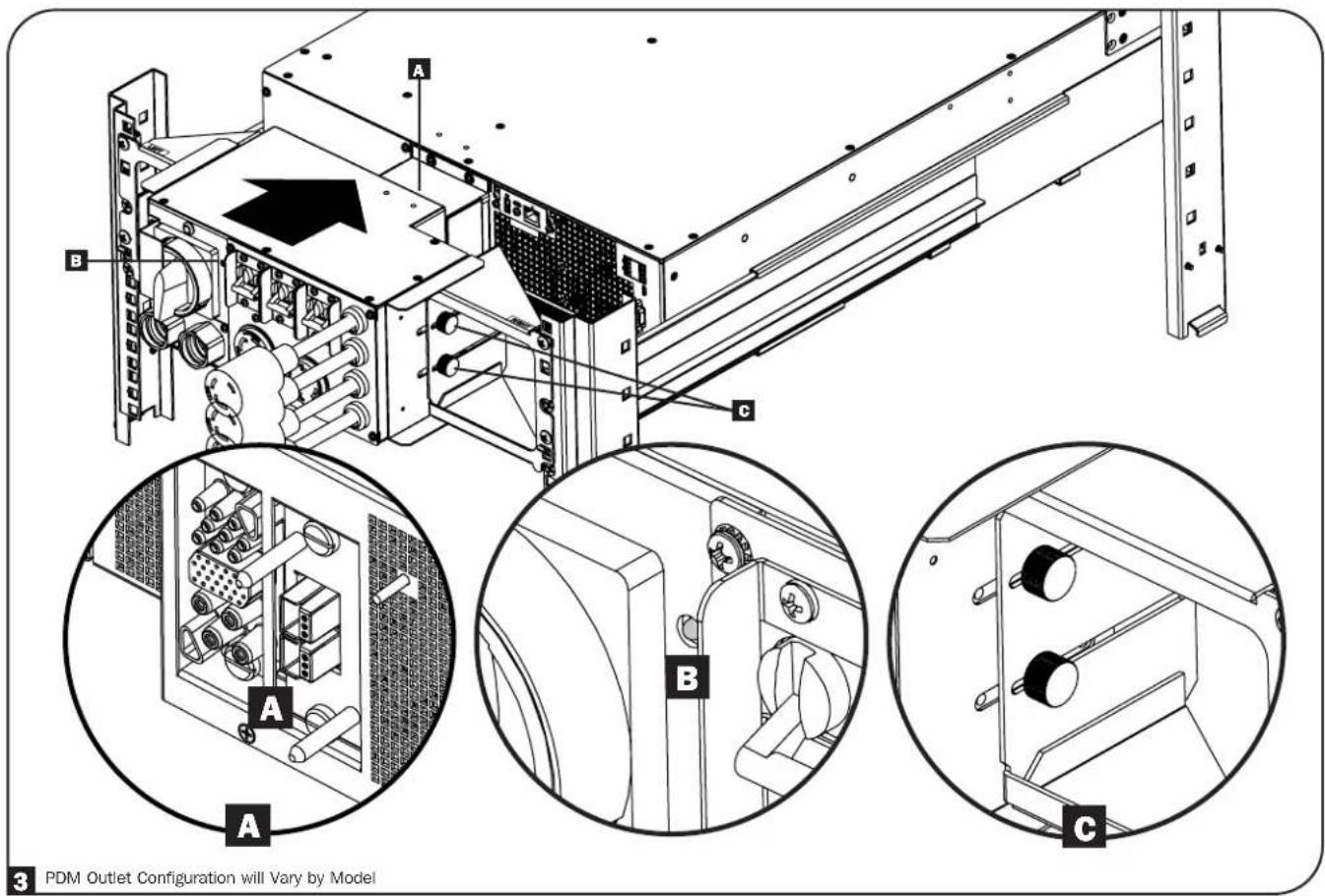
2 PDM Outlet Configuration will Vary by ModelInstallation
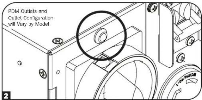
3 Push the PDM toward the UPS so its blindmate connectors securely mate with the connectors on the UPS A. A green pin will appear on the PDM's front panel to indicate a proper connection B. Once the PDM and UPS are properly mated, tighten the thumb screws C.
text_image
3 PDM Outlet Configuration will Vary by ModelMounting the Power Distribution Module in Extra-Deep Rack Enclosures
1 Use the included M4 x 6 mm Phillips Screws to attach the Deep Rack Extension Brackets to the PDM.

text_image
PDM Outlet Configuration will Vary by Model 1Installation
2 Using the thumbscrews, attach the PDM Mounting Brackets to the Deep Rack Extension Brackets.

To attach the PDM assembly to a 4-post rack, refer to Mounting the Power Distribution Module in Standard-Depth Rack Enclosures, instructions 2 and 3.
text_image
2 PDM Outlet Configuration will Vary by Model2-Post Mounting
If you mount 2U UPS models in 2-post racks, they require the addition of a Tripp Lite 2-Post Rack-Mount Installation Kit (model: 2POSTRMKITMB, sold separately). See Installation Kit owner's manual for installation procedure.
Installation
Tower Mounting

WARNING!
All UPS systems are extremely heavy. Use caution when lifting and mounting. User must properly stabilize the UPS when lifting and mounting.
Your UPS can be mounted in an upright tower position with optional base stands sold separately by Tripp Lite (model: 2-9USTAND). When mounting the UPS on adjustable base stands, make sure the LCD panel is facing toward the top.
The LCD panel may be rotated for easier viewing while the UPS is upright. To rotate, insert a small screwdriver or other flat-edge tool into the slots on any side of the LCD panel. Pop the panel out, rotate accordingly and snap it back into place.

WARNING: Display circuitry is not isolated. Display rotation must be performed only by qualified electrical service personnel.

natural_image
Technical line drawing of a mechanical assembly with mounting flanges and a vertical panel (no text or symbols)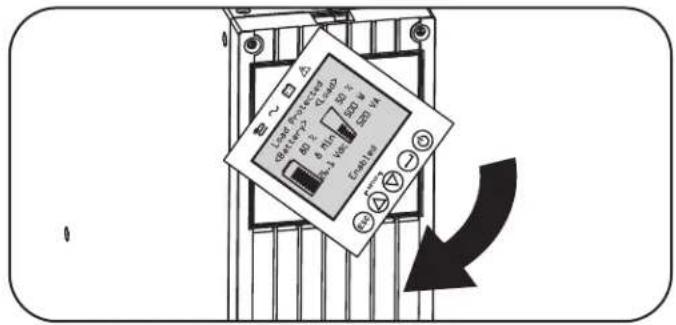
text_image
Loop Power Source 80 V 6 Min 300 V 300 W Load LoadTo attach the PDM unit, use the included screws to attach the Tower Mounting Plate to the UPS A. Align and mate the PDM's blindmate connectors with the connectors on the UPS B. A green pin will appear on the PDM's front panel to indicate a proper connection C. Use the thumbscrews to secure both sides of the PDM unit to the UPS via the Tower Mounting Plates D.
text_image
PDM Outlet Configuration will Vary by Model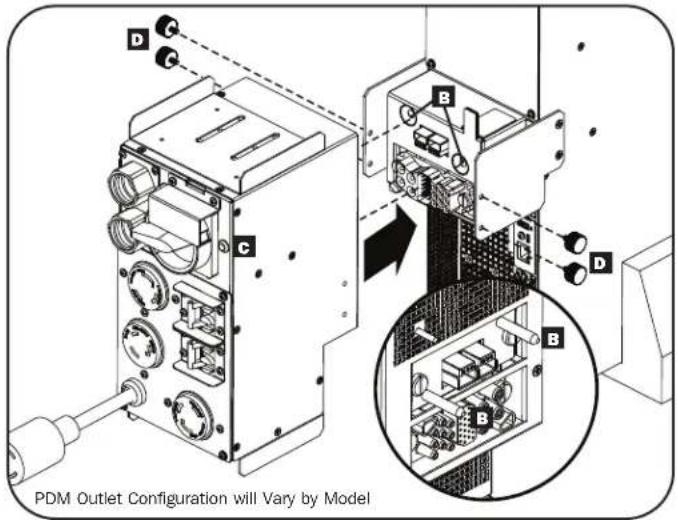
text_image
PDM Outlet Configuration will Vary by ModelEXTERNAL BATTERY CONFIGURATION NOTE
If external battery packs are to be used with this UPS, install them following the mounting/installation documentation included with each battery pack.
These SmartOnline UPS systems support automatic detection of up to four compatible Tripp Lite Smart battery packs. Each Smart battery pack includes a wired data connection that enables automatic detection and configuration for up to four Smart external battery packs to the UPS. If more than four external battery packs need to be configured, all packs must be configured via the Tripp Lite external battery configuration software connecting though the UPS serial port. In this configuration, do not connect the Smart battery communication cables to any of the external battery packs.
Installation
Input and Output Wiring Instructions (Optional with Select Models)
Note: The tightening torque is 1 n·m (10 lb·in.).
CAUTION: This type of connection must be performed by qualified professional electrical service personnel only. When making connections, check that the mains power to the UPS is OFF. Connect the ground wires from the cables to the chassis ground lug. Always connect the ground wire first.
Be sure to observe the Input Line Configuration, Breaker and wire AWG as outlined in the UPS Input and Output Overview table, detailed in this section.
Note: Select models include an AC input cord with L6-30P plug. If this AC cord is to be used, the UPS input/output power capacity ratings will change. See the UPS nameplate for more information.
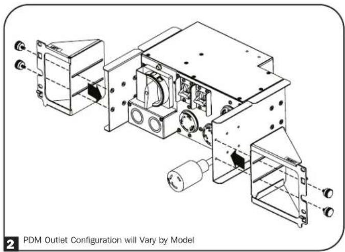
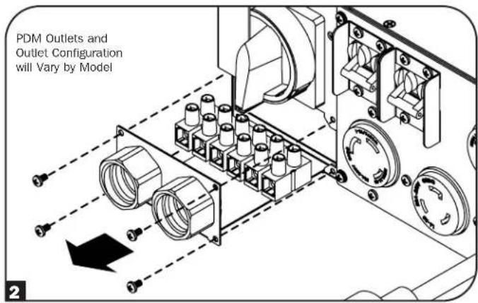
1 Detach the PDM from the UPS.
Hardware Input/Output models: Before removing the terminal block cover ensure that flexible conduits used for hardwire input and output are the correct length to reach the fixed knockout locations on PDM. Remove the appropriate knockout sized for your conduit from both Hardwire Input and Hardwire Output locations on the PDM terminal block cover.
Corded Models: Remove the knockout from the Hardwire Input location on the terminal block cover.
Note: If you will use hardwire output in combination with UPS models with outlets, remove the appropriate hardwire output knockout at this time.
2 Unscrew the four screws to remove the terminal strip cover and slide out.
3 Hardwire Models: Insert and secure the included user-supplied strain reliefs or connectors and secure to terminal block cover.
Corded Models: Attach and secure one of the included strain reliefs to the hardwire input side of terminal cover. Pass the included hardwire side of the cord with L6-30P plug. Do not tighten outer part of strain relief at this time.
4 Hardware Models: Connect the two sets of L1, L2/N and Ground wires (1 Input, 1 Output) according to markings on the terminal block. Be sure to connect one set of wires to the input terminals and the other set to the output terminals.
Corded Models: Pass input cord through strain relief. Connect and secure the input cord wire connections to the L1 In, L2/N In and input ground hardwire terminals. Tighten the outer strain relief.
Note: If hardwired output is used in combination with models that have outlets, connect the device wiring to the L1 Out, L2/N Out and output ground hardwire terminals at this time.
5 Slide in and reattach the terminal strip cover with the four screws removed in step 2.
text_image
PDM Outlets and Outlet Configuration will Vary by Model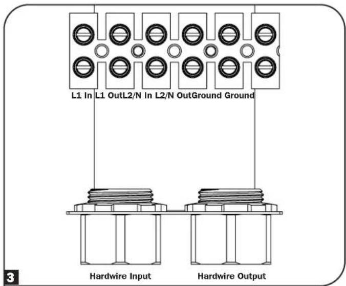
text_image
L1 In L1 OutL2/N In L2/N OutGround Ground 3 Hardwire Input Hardwire Output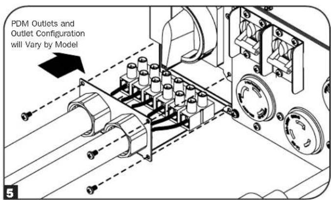
text_image
PDM Outlets and Outlet Configuration will Vary by ModelInstallation
UPS Input and Output Overview
| Model Name | Input Connection | Input Line Configuration | Building Breaker C-Curve Input AWG (mm ^2 ) | Receptacle Plate Configuration | |
| SUPDMB5 HW L1, L2/N, | PE(GND) 40 8 (6) |  | |||
| L6-30P L1, L2/N, PE(GND) 30 10 (4) | |||||
| SUPDMB5P L6-30P L1, | L2/N, PE(GND) 30 10 (4) | ||||
| SUPDMB5G HW L1, L2/N, PE(GND) 40 8 (6) | 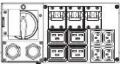 | ||||
| SUPDMB5HW HW L1, L2/N, PE(GND) 40 8 (6) None | |||||
| SUPDMB6 HW L1, L2/N, | PE(GND) 50 6 (10) | 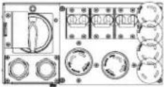 | |||
| L6-30P L1, L2/N, PE(GND) 30 10 (4) | |||||
| SUPDMB6P L6-30P L1, | L2/N, PE(GND) 30 10 (4) | ||||
| SUPDMB6IEC HW L, N, PE 50 6 (10) | 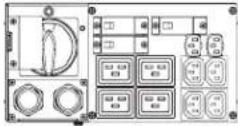 | ||||
| SUPDMB6G HW L1, L2/N, PE(GND) 50 6 (10) | 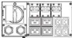 | ||||
| SUPDMB6HW HW L1, L2/N, PE(GND) 50 6 (10) None | |||||
Features
Before installing and operating your UPS, familiarize yourself with the locations and function of the features of each component.
Front Panel Controls, LEDs and LCD Screen
The graphical LCD on the front panel contains a wide range of UPS operating conditions and diagnostic data. It also displays UPS settings and options when viewing the UPS setup screens. The five buttons below the LCD can be used to navigate the various information, configuration and UPS control screens by following the on-screen prompts and selection options. Additional LED indicators above the LCD screen also provide at-a-glance status of AC input source, availability of output, battery status, and warning/fault status.
See Operations section for detailed descriptions of LCD functions, buttons and LEDs.
text_image
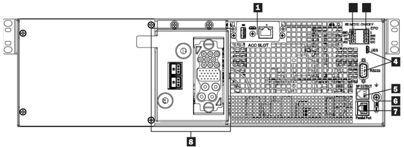
Load ProtectedUPS Rear Panel
text_image
1 REMOTE ON/OFF EPO X GND EPO VCC ACC SLOT USB 4 RS232 5 BP DETECT 6 7 Parallel Port 81 Accessory Slot: Remove the small cover panel from this slot to use optional accessories to remotely monitor and control your UPS. Visit tripplite.com to see a full list of accessories, including a wide variety of network management and connectivity products.
2 Remote On/Off: The UPS supports connection of a remote On/Off switch. This port may be used to connect the UPS to a contact closure switch to turn off the UPS system remotely. Make sure to use the terminal block on the left side labeled for remote On/Off connection. See Optional Connections section for details.
3 EPO (Emergency Power Off) Port: Your UPS features a port that may be used to connect the UPS to a contact closure switch to enable emergency shutdown of your UPS. Make sure to use the pins on the right terminal block labeled for EPO. See Optional Connections section for details.
4 Communications Ports: These ports (USB or RS-232) connect your UPS to any workstation or server. Use with Tripp Lite's PowerAlert Software and included cable to enable your computer to automatically save open files and shut down equipment during a blackout. Also use PowerAlert Software to monitor a wide variety of AC line power and UPS operating conditions. Consult your PowerAlert Software manual or contact Tripp Lite Customer Support for more information. The 9-pin RS-232 port also supports dry-contact communications. See USB & RS-232 Dry Contact Communications in the Optional Connections section for installation instructions.
5 External Battery Pack Detection Port: For external batteries with communication built-in, plugging the battery communication cable into this port will allow the UPS to automatically detect smart battery packs. See the Configuring External Battery Packs in the Operations section for configuration instructions.
6 Chassis Ground Screw: Use this to connect any equipment that requires a chassis ground.
7 Parallel Port: Reserved for future use.
8 Blindmate Power Connection Box: Connects the UPS to the detachable PDM (see PDM Panel for details by model).
Features
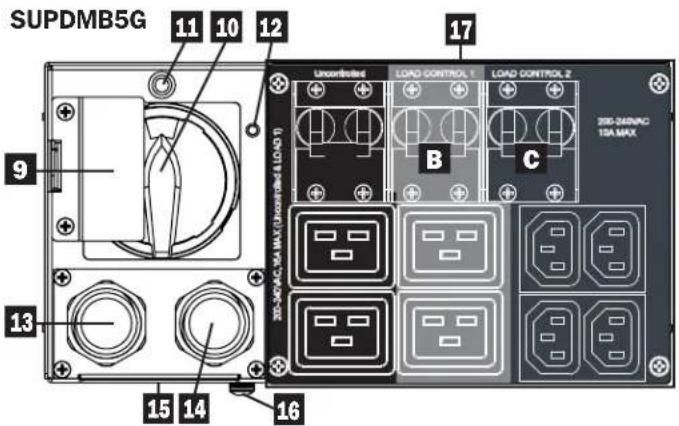
PDM Panel
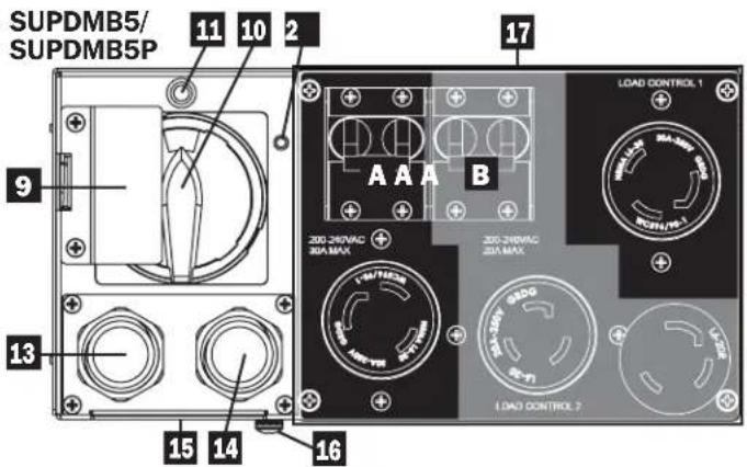
text_image
SUPDMB5/ SUPDMB5P 11 10 2 9 13 15 14 16 AAA B LOAD CONTROL 1 200-250VAC 30A MAX 200-250VAC 20A MAX LOAD CONTROL 7| Load Bank | Receptacles Breaker | |
| A | 2x L6-30R 1x 2-Pole (30A) | |
| B | 2x L6-20R 1x 2-Pole (20A) | |
text_image
SUPDMB5G 11 10 12 9 13 15 14 16 Uncontrolled LOAD CONTROL 1 LOAD CONTROL 2 LOAD(0)1-Insulation(D:\VM-76\V-0.5\V-30) B C 330-340VAC 13A MAX| Load Bank | Receptacles Breaker | |
| A* | 2x C19 1x 1-Pole | (16A) |
| B | 2x C19 1x 1-Pole | (16A) |
| C | 4x C13 1x 1-Pole | (10A) |

text_image
SUPDMB6/ SUPDMB6P 11 10 12 9 13 15 14 16 LOAD CONTROL 1 LOAD CONTROL 2 LOAD CONTROL 3 A B C 200-240VAC.30A MAX| Load Bank | Receptacles Breaker | |
| A | 2x L6-30R 1x 2-Pole (30A) | |
| B | 2x L6-20R 1x 2-Pole (20A) | |
| C | 2x L6-20R 1x 2-Pole (20A) | |

text_image
SUPDMB6IEC 11 10 12 9 13 15 14 16 LOAD CONTROL 1 200-267VAC 10A MAX A B C LOAD CONTROL 2 200-248VAC 10A MAX LOAD CONTROL 3 200-247VAC 10A MAX| Load Bank | Receptacles Breaker | |
| A | 2x C19 1x 1-Pole | (16A) |
| B | 2x C19 1x 1-Pole | (16A) |
| C | 6x C13 1x 1-Pole | (10A) |

text_image
SUPDMB6G A 11 10 L 12 S: Bottom vie 9 13 15 14 LOAD CONTROL 1 LOAD CONTROL 2 LOAD CONTROL 3 A B C 200-240VAC 10A MAX| Load Bank | Receptacles Breaker | |
| A | 2x C19 1x 2-Pole | (16A) |
| B | 2x C19 1x 2-Pole | (16A) |
| C | 4x C13 1x 2-Pole | (10A) |
text_image
15 16*Uncontrolled Load Bank
Features
9 Bypass Switch Cover: Prevents the Maintenance Bypass Switch from being set to BYPASS before putting the UPS in Electronic Bypass mode.
10 Maintenance Bypass Switch: Allows qualified service personnel to remove the UPS for routine maintenance without disrupting power to connected loads. While this switch is set to BYPASS, connected equipment will receive filtered AC mains power, but the equipment will not receive battery power in the event of a blackout. See PDM Maintenance Bypass Procedure section for more information.
11 UPS Bypass Disabled LED (red): When attempting to enter Maintenance Bypass Mode via the Maintenance Bypass Switch, if this LED is illuminated, the UPS is not in a valid state to switch the Maintenance Bypass Switch to the "BYP" position. Doing so would result in the load being dropped.
When attempting to exit Maintenance Bypass Mode via the Maintenance Bypass Switch, if this LED is illuminated, the UPS is not in a valid state to switch the Maintenance Bypass Switch to the "NORM" position. Doing so would result in the load being dropped.
12 UPS/PDM Mating Pin: Indicates a proper connection between the PDM's blindmate connectors and the connectors on the UPS.
13 AC Input Connection: Connects to AC power via an attached power cord or hardwire connection.
Note: SUPDMB5G and SUPDMB6 models include an optional input cord. SUPDMB5P and SUPDMB6P models include a pre-installed input cord.
14 AC Output Connection (optional on select models): Connects to an AC load via hardwire connection (See Hardware Input and Output Wiring Instructions for more information.
Note: The total load connected to the UPS must not exceed the maximum nameplate load rating.
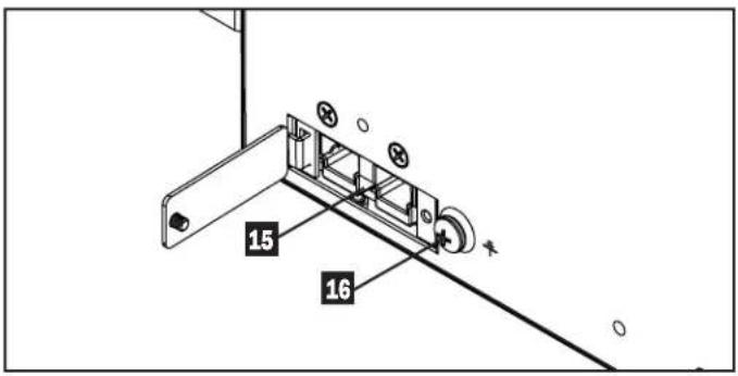
15 External Battery Pack Connector (located on the PDM's bottom panel): Your UPS features a robust internal battery system. Adding external batteries will increase runtime and recharge time. See Additional Accessories (Optional) in the Overview section for compatible models and Configuring External Battery Packs section under Operations section for configuration instructions.
Note: Do not connect or disconnect battery packs when the UPS is running on battery power.
16 DC Ground Screw: Use this to create a ground connection between the UPS and an attached external battery pack.
17 AC Receptacles (varies by model): These output receptacles provide connected equipment with pure sine-wave AC output during normal operation and battery power during blackouts and severe brownouts. The receptacles are divided into load banks, as described on the unit. Using PowerAlert software and cabling, load banks may be individually turned off and on from a remote location, allowing users to reset or reboot connected equipment.
Operations
This section explains how to use your Tripp Lite Online UPS System, including front-panel LCD operation, operating modes, UPS startup and shutdown, transferring between modes, setting power strategy, and configuring bypass settings, load segments and battery settings.
LCD Front Panel Display and Controls
A 5-button graphical LCD screen with additional LED indicators on the front of the UPS that provides information on UPS status, load level information, event information, measurements, settings and a wide variety of UPS configuration and power strategy options.
text_image
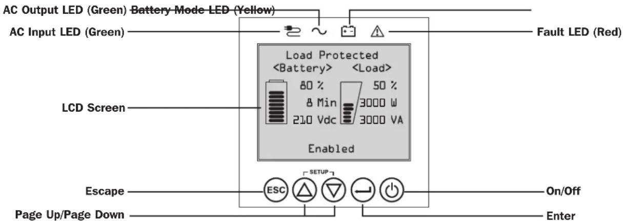
AC Output LED (Green) Battery Mode LED (Yellow) AC Input LED (Green) Load ProtectedOperations
LED Front Panel Indicators
There are 4 LEDs above the front panel LCD screen that offer information on AC INPUT, BYPASS, AC OUTPUT, BATTERY MODE and UPS FAULT status.

AC INPUT indicator
On AC input is available AND AC input is WITHIN the configured ECONOMY / BYPASS mode range. When this LED is ON SOLID, AC input is of adequate quality for UPS operation in BYPASS or ECONOMY MODE.
Flashing AC input is available AND AC input is OUTSIDE the configured BYPASS mode range. When this LED is ON FLASHING, AC input is not of adequate voltage or frequency for UPS operation in BYPASS or ECONOMY MODE.
Off AC input is NOT available.
When this LED is OFF, AC input is not available.

AC OUTPUT indicator
On UPS AC output is ON UPS output is available at the UPS output receptacles.
Off UPS AC output is OFF UPS AC output is not available.

BATTERY MODE indicator
On UPS is running in battery mode UPS batteries are discharging as the UPS runs in battery mode. Also lights momentarily during self-test operation.
Flashing UPS is running in battery mode - Low battery warning UPS batteries are discharging as the UPS runs in BATTERY mode and are becoming low. The indicator will flash at 2-second intervals to report LOW BATTERY and 0.5-second intervals to report BATTERIES ARE NEAR FULLY DISCHARGED and the UPS is near shutdown.

UPS FAULT indicator
On UPS is experiencing a pre-defined fault state See front panel display for explanation of error state or code information. See on-screen instructions and manual for troubleshooting tips.
Off Normal UPS is not reporting fault conditions when this indicator is OFF.
Operations
Front Panel Button Functions
There are 5 front panel buttons that offer UPS control and configuration options. To navigate the various information, configuration and UPS control screens, use the 5-button front panel interface and follow the on-screen prompts and selection options.

Power On / Off Button: This control offers three main functions: Power-On, Power-Off and Clear UPS Fault.
To turn the UPS ON into a protected operating mode, press and hold this button for 3 seconds as the UPS is connected to input AC power. Release the button when the alarm begins to sound and the UPS will startup into the last configured power strategy.
To "cold start" the UPS ON into battery mode during power failure conditions, press and hold this button for 3 seconds. Release the button when the alarm begins to sound and the UPS will startup in battery mode.
To turn the UPS OFF as it's running in battery or protected mode, press and hold this button for 3 seconds. Release the button when the alarm begins to sound. The UPS will turn off AC output. Once AC output is off, disconnect input power to the UPS and the UPS will power off completely.
To CLEAR UPS FAULT, press and hold this button as directed on-screen for 3 seconds. The UPS will clear the fault conditions and return to standby or bypass mode.

ENTER Button: This control is used to make selections, confirm options and move forward to the next selection as the UPS is configured in setup mode. Press this button as directed on-screen in Setup mode to Enter, Confirm or Move Forward in the configuration process.

UP / DOWN Buttons: These controls offer two main functions: "Up" and "Down" directional control, plus enter / exit setup mode. These buttons are used to navigate setup-mode menu options and scroll up or down to view screen contents as necessary.

To ENTER or EXIT UPS SETUP MODE, press one of these two buttons for 3 seconds. The UPS will automatically enter setup mode if one of these buttons is pressed during LCD display modes. The UPS will automatically exit setup mode if one of these buttons is pressed as the UPS runs in UPS setup mode.

ESCAPE Button: This control offers three main functions: Alarm Cancel, Clear Fault and Back / Cancel operations.
To CANCEL UPS ALARM, press this button. If a new alarm condition occurs, the alarm will sound again.
To CANCEL or GO BACK ONE LEVEL, press this button as directed on-screen in Navigation and Setup modes.
Home Screen Layout
The UPS front panel LCD screen is set up to provide continuous UPS operating information using NORMAL MODE and BATTERY MODE home-screens that continuously report operating mode, protection status, power strategy and a number of battery and load-level operating parameters.
Normal Mode Home Screens
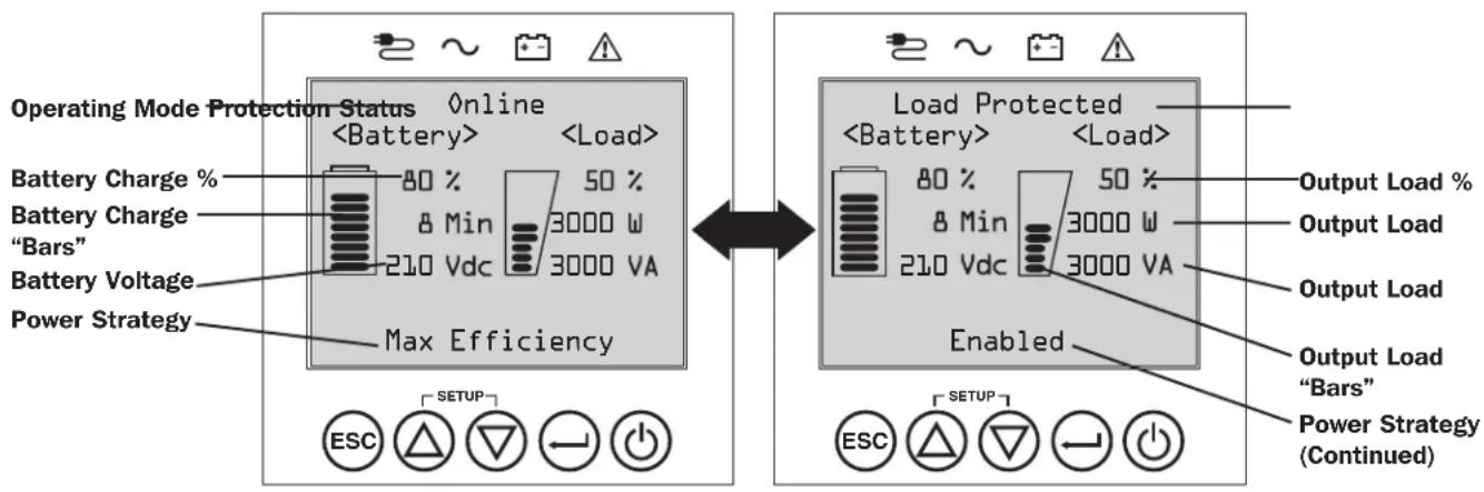
text_image
Operating Mode Protection Status OnlineOperations
Basic Connection and Start-Up
1 Connect your UPS to electrical service
Your UPS must be connected to a dedicated circuit of sufficient amperage. L6-30 models require a 30A building installation breaker. For Hardwire models, refer to the Installation section, UPS Input and Output Overview Table and rating on the UPS for details.
2 Plug your equipment into the UPS
When input power is applied, the UPS will go into Standby Mode and the batteries will charge.
Your UPS is designed to support network, server and computer equipment only.
Note: If the equipment is to be load controlled, make sure to plug equipment into a load-controlled bank.
3 Turn your UPS on
Press and hold the POWER ⏻ button for 3 seconds and release as the alarm begins to sound.
4 Select your Language
When your UPS is powered up for the first time, the INPUT AC LED will light up and the front panel LCD screen will request a language selection.
Using the UP / DOWN buttons Ⓐ, select your language preference, then press the NEXT ⏰ button.
The interface will confirm your selection and provide options to go back (press BACK ⏻) or to go to the next step (press NEXT ⏻).

natural_image
Line drawing of a plug inserted into an electrical socket (no text or symbols)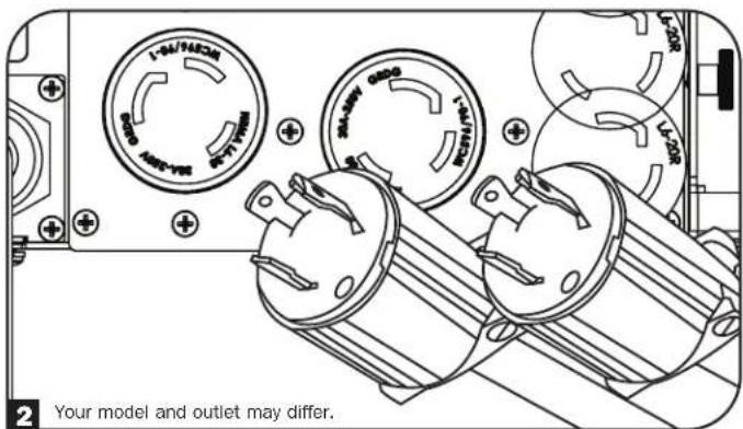
text_image
1-5V/50CM 5V/50CM 5V/50CM 5V/50CM 5V/50CM 5V/50CM 5V/50CM 5V/50CM 5V/50CM 5V/50CM 5V/50CM 5V/50CM Your model and outlet may differ.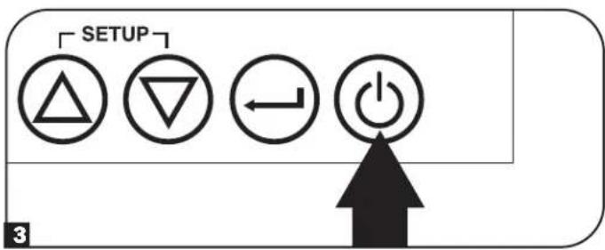
text_image
SETUP 3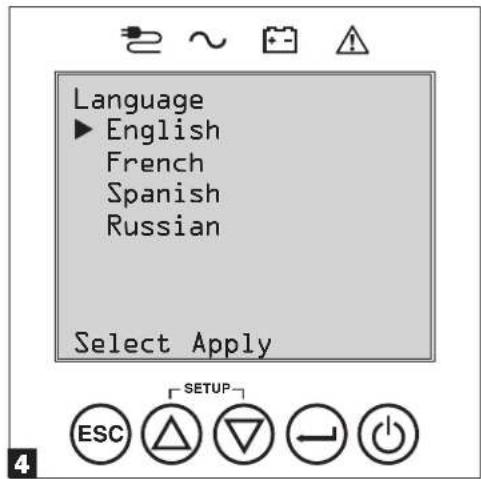
text_image
Language ► English French Spanish Russian Select Apply ESC SETUPOperations
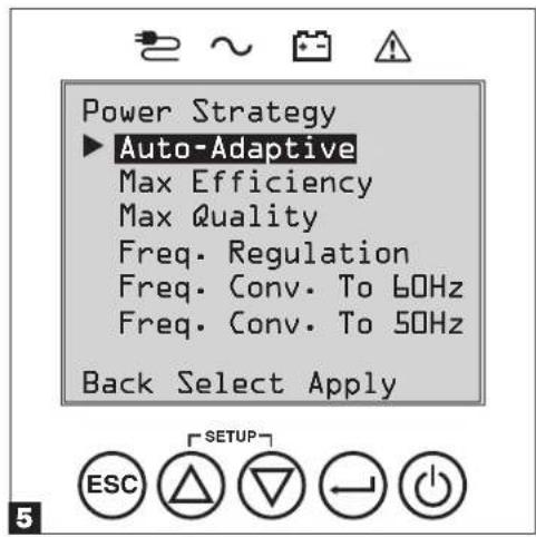
5 Select your Power Strategy
Next, the UPS will prompt you to pick the desired POWER STRATEGY.
Using the UP / DOWN Ⓐ buttons, select your POWER STRATEGY preference and press the APPLY ⏻ button.
See the Power Strategy Selection Options and UPS
Operating Modes sections under the Operations section for operating characteristics of each power strategy.
6 Select your Password
Next, the UPS will prompt you to pick the desired PASSWORD.
Using the UP / DOWN Ⓐ buttons, select the first digit of your desired password and press the NEXT ⏰ button to advance to the second digit. Repeat for digits 2 through 4.
Note: To quickly set the password to "O O O O" press the NEXT button 4 times.
7 Select UPS Output Voltage
Next, the UPS will prompt you to select the desired OUTPUT VOLTAGE.
Using the UP / DOWN Ⓐbuttons, select the UPS output voltage, then select APPLY ⊖.
text_image
Power Strategy ► Auto-Adaptive Max Efficiency Max Quality Freq. Regulation Freq. Conv. To 60Hz Freq. Conv. To 50Hz Back Select Apply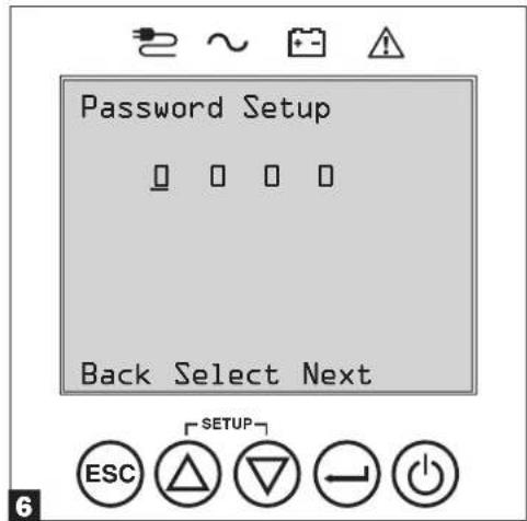
text_image
Password Setup Back Select Next ESC SETUP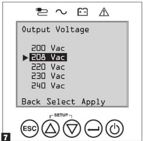
text_image
Output Voltage 200 Vac ▶208 Vac 220 Vac 230 Vac 240 Vac Back Select Apply ESC SETUPOperations
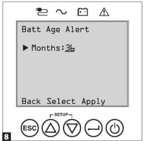
8 Select UPS Battery Age Alert
Next, the UPS will prompt you to select the timing of the Battery Age Alert notification from between 12-60 months. The default setting is Disabled.
Using the UP / DOWN Ⓐ buttons, select the timing of the battery age alert in months, then press APPLY⊖.
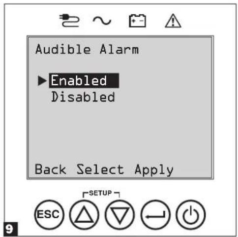
9 Select Audible Alarm ENABLED / DISABLED status
Next, the UPS will prompt you to select the alarm ENABLED / DISABLED status.
Using the UP / DOWN Ⓐ buttons, select the alarm ENABLED / DISABLED status, then press APPLY⊖.
Note: Disabling the alarm prevents the audible alarm from sounding during power failures and UPS fault conditions only. The alarm will still "chirp" to confirm operator input via the front panel LCD navigation buttons when the alarm is set to disable.
The UPS will then go through a series of diagnostic checks before turning on output power. Once the UPS reports the operating status of NORMAL / LOAD PROTECTED with the configured POWER STRATEGY enabled, your UPS can immediately be put into service to provide reliable protection from a wide variety of power problems.
text_image
Batt Age Alert ► Months:36 Back Select Apply ESC SETUPRange: 12 to 60, Default: Disabled
text_image
Audible Alarm ▶Enabled Disabled Back Select Apply ESC SETUPOperations
Power Strategy Selection Options
Tripp Lite SmartOnline LCD UPS systems offer several built-in power strategy options that enable the UPS to optimize performance to meet user needs for MAXIMUM POWER QUALITY, MAXIMUM EFFICIENCY, and FREQUENCY REGULATION or FREQUENCY CONVERSION operation. An additional AUTO-ADAPTIVE power strategy combines the benefits of high-efficiency and maximum power quality. Each power strategy option enables the UPS to automatically shift between specific operating modes as power and UPS status dictates. Available power strategy options include:
- Auto-Adaptive Power Strategy enables the UPS to automatically switch between ONLINE MODE and ECONOMY MODE as dictated by the quality and reliability of UPS input power. If the UPS does not experience a power failure in a week's time (not including UPS self-test) the UPS will automatically switch to ECONOMY MODE. If a power failure occurs, the UPS will maintain output in BATTERY MODE. When power is restored, the UPS will repeat the cycle by running in ONLINE MODE until there are no power failures for one week's time. Auto-bypass mode is available during UPS failure modes when AC input is within the bypass range.
- Max-Efficiency Power Strategy enables the UPS to run continuously in ECONOMY MODE anytime incoming AC power is within the configured bypass low/high voltage range. If UPS input voltage is outside the configured bypass range, the UPS will automatically switch to ONLINE MODE until AC input voltage is restored within the configured bypass voltage range. This is similar to Auto-Adaptive Power Strategy, except transfer to ECONOMY MODE is immediate as voltage levels recover. There is no one-week time period of power failure free operation required in order for the UPS to return to ECONOMY MODE operation. Auto-bypass mode is available during UPS failure modes when AC input is within the bypass range.
- Max-Quality Power Strategy enables the UPS to run continuously in ONLINE MODE the entire time incoming AC power is within the range for online mode operation. The UPS will remain operating continuously in Online Double-Conversion mode, providing the highest quality output power with zero transfer time. Auto-bypass mode is available during UPS failure modes when AC input is within the bypass range.
- Frequency Regulation Power Strategy is similar to Max-Quality Power Strategy, except the UPS will actively regulate output frequency within ± 0.5 Hz of the 50 or 60Hz nominal frequency measured on startup. The UPS will remain operating continuously in Online Double-Conversion mode, providing the highest quality output power with zero transfer time.
Note: Auto bypass during a fault is available. Bypass is not available when the UPS is in Off Mode.
- Frequency Conversion to 60 Hz & Frequency Conversion to 50 Hz Power Strategies are similar to Max-Quality power strategy, except the UPS will actively regulate output within +/- 0.5 Hz of the 50 Hz (Freq. Conv. to 50 Hz setting) or 60 Hz (Freq. Conv. to 60 Hz setting). Auto-bypass is not available in FREQUENCY CONVERSION mode. Typical applications include converting 50 to 60 Hz (or 60 to 50 Hz) for sensitive electronic devices.
Note: Maximum power supported in Frequency Conversion modes is derated by 30%. Auto bypass during a fault is not available.
UPS Operating Modes
Tripp Lite SmartOnline UPS systems are able to automatically switch between operating modes under conditions specified in the configured Power Strategy. The UPS continuously indicates status using front panel LEDs and the interactive LCD viewing screen.
- Battery Mode is the UPS system's automatic response to power failures and voltage variations outside of the online voltage range. In BATTERY MODE, the UPS maintains sine wave AC output power from battery reserves. Once power is restored, the UPS will return to the protected operating mode as dictated by the configured power-strategy and input power conditions.
- Online Mode (also known as ONLINE, DOUBLE CONVERSION MODE) offers the highest level of UPS equipment protection. In ONLINE MODE, the UPS actively regenerates power from AC to DC, then from DC to AC to provide continuously regulated AC output within 2% of the selected nominal output voltage with zero transfer time as the UPS switches between ONLINE and BATTERY modes.
- Economy Mode offers power saving operation with the highest level of UPS operating efficiency. In ECONOMY MODE, the UPS saves energy by turning off the online, double-conversion process whenever input power is within the ECONOMY MODE voltage range. If line voltage or frequency falls outside of the ECONOMY MODE, the UPS will respond by automatically switching to ONLINE MODE until line voltage recovers.
- Frequency Regulation Mode gives the UPS the ability to correct frequency variations present on UPS input power. See Power Strategy Selection Options section for details.
- Frequency Conversion to 60 Hz and Frequency Conversion to 50 Hz Modes give the UPS the ability to convert frequency from 50 Hz to 60 Hz (or 60 Hz to 50 Hz). The output frequency is fixed at 60 Hz or 50 Hz, based on the selected frequency setting. The UPS will accept input frequency from 40-70 Hz and convert, as needed. See Power Strategy Selection Options section for details.
Note: Maximum power supported in Frequency Conversion modes is derated by 30%.
- Bypass Mode offers filtered and unregulated power to connected equipment.
Operations
Power Strategy Operating Features and Supported UPS Operating Modes
The configured UPS Power Strategy provides a framework for UPS operation as it switches between operating modes as dictated by power events and UPS status. Each Power Strategy offers a unique set of operating parameters that the UPS adheres to in order to meet user preferences for high performance or high efficiency. Additional frequency regulation and conversion options are also available for advanced applications. The chart below lists the UPS operating modes supported for each Power Strategy option.
| UPS OPERATING MODESUPS automatically switches operating modes as dictated by the configured power strategy, current power and UPS status conditions. | |||||
| Support for ONLINE MODE | Support for ECONOMY MODE | Support for BATTERY MODE | Support for AUTO-BYPASS | ||
| POWER STRATEGY SELECTION OPTIONSSYour power strategy selection enables the UPS to switch between operating modes as described. | AUTO ADAPTIVEUPS runs continuously in ECONOMY MODE after running in ONLINE MODE for one continuous week without a power failure. | YES. When input is within the ONLINE voltage range, but outside the BYPASS voltage range, and after AC power is restored. | YES. When input is within the ECONOMY MODE voltage range and there are no power failures for one week. | YES. YES. In the event of UPS | inverter fault while input voltage is within the BYPASS voltage range. |
| MAX. QUALITYUPS runs in ONLINE MODE continuously to maintain the highest quality output power for connected equipment. | YES. When input is within the ONLINE voltage range. | NO. YES. YES. In the event of UPS | Inverter fault while input voltage is within the BYPASS voltage range. | ||
| MAX. EFFICIENCYUPS runs in ECONOMY MODE full time when input is within the bypass range. | YES. When input is within the ONLINE voltage range, but outside the BYPASS voltage range. | YES. When input is within the ECONOMY MODE voltage range. | YES. YES. In the event of UPS | inverter fault while input voltage is within the BYPASS voltage range. | |
| FREQUENCY REGULATIONUPS regulates output to within ±0.5 Hz of nominal. | YES. When input is within the ONLINE voltage range.* | NO. YES. YES. In the event of UPS | Inverter fault while input voltage is within the BYPASS voltage range. | ||
| FREQUENCY CONVERSION TO 60 HzUPS converts to 60 Hz (±0.5 Hz). | YES. When input is within the ONLINE voltage range.** | NO. YES. NO. | |||
| FREQUENCY CONVERSION TO 50 HzUPS converts 60 Hz input to 50 Hz (±0.5 Hz). | YES. When input is within the ONLINE voltage range.** | NO. YES. NO. | |||
* LCD displays FREQUENCY REGULATION as the operating mode with derating information.
** LCD displays FREQUENCY CONVERSION as the operating mode with derating information.
Operations
Front Panel LCD Selection and Configuration Options
| MAIN MENU / SUBMENU DISPLAY / SETTING OPTIONS DISPLAY / SETTING DESCRIPTION | ||
| STATUS | ||
| Load Status • Load level (%, kW, kVA, A, PF)• Available capacity (%, kW, kVA) | UPS load percent (%), kilowatt (kW), kilovoltamp (kVA), amp (A) & power factor (PF).UPS capacity available in percent (%, kilowatts (kW) & kilovoltamps (kVA). | |
| In/Out Status • Input voltage & frequency (Vac, Hz)• Output voltage & frequency (Vac, Hz)• Load Group 1 (On, Off)• Load Group 2 (On, Off)• Load Group 3 (On, Off) | Displays UPS input and output status information for input / output voltage (Vac), frequency (Hz) and outlet group power status (On/Off) information. | |
| Energy Status • Efficiency (%) | • Avg. Power (kw/hr.)• Configured power strategy | Displays UPS efficiency percentage (%, connected equipment kilowatt hour consumption (kw/hr.) and configured power strategy. |
| Battery Status • Battery model & serial number• Installed (mm/dd/yyyy)• Expires (mm/dd/yyyy) | Displays Battery Pack model number & serial number (Tripp Lite SMART BATTERY PACKS) only, installation date and user configured expiration date. | |
| Power Flow Chart • View UPS operationa flow chart Displays UPS operating mode in a graphical flow chart. | ||
| CONTROL | ||
| Start Batt. Test | • Initiates a manual battery test | Initiates a momentary UPS battery self-test with immediate Pass/Fail results. |
| Reset Fault State | • Resets any fault state messages | Use this option to clear UPS fault messages. |
| Auto Batt. Testing | • Set regular battery self-test interval○ Disable○ 4 weeks (factory setting)○ 13 weeks○ 26 weeks | Use this option to initiate automatic UPS battery testing at regular intervals. |
| EVENT LOG | ||
| On Batt. Events | • Event counter(UPS On-battery events only)• Total minutes (total minutes of on-battery mode operation)• Most recent power failure (date)• Months until battery replacement alert (months)• Event details (date, time & description for the last 20 logged events) | Displays a summary of all ON-BATTERY events where the UPS switched to battery mode in response to a protected condition.Event details lists the last 20 battery events. As additional alerts occur, the oldest records will be automatically removed. |
| All Events | • Event counter (all events)• Most recent event (date)• Date time log | Displays a summary of all Recorded events. Event details lists the last 20 events. As additional alerts occur, the oldest records will be automatically removed. |
| SETTINGS | ||
| Basic setup | System• Current date (display, set date)• Current time (display, set time)• Audible alarm (enable, disable)• Language (select) | Displays, sets and resets date, time, audible alarm status and language settings.Note: Audible Alarm DISABLE setting prevents power fail and operating fault alarms only, the UPS will always “beep” to confirm the UPS is accepting user input from the front-panel LCD navigation buttons.Note: The current date and current local time are reported directly from the remote management card. |
| Output voltage• 200• 208• 220• 230• 240 | Use the SETTINGS / BASIC / OUTPUT VOLTAGE option to display or set the nominal UPS output voltage (changes take effect on next restart). | |
Operations
| MAIN MENU / SUBMENU DISPLAY / SETTING OPTIONS DISPLAY / SETTING DESCRIPTION | ||
| SETTINGS | ||
| Basic setup(continued) | Power strategy:• Auto-Adaptive• Max Efficiency• Max Quality• Freq. Regulation• Freq. Conversion to 60 Hz• Freq. Conversion to 50 Hz | Use the SETTINGS / BASIC / POWER STRATEGY option to display or set the UPS Power strategy.SeePower Strategy Selection Optionssection under the Operationssection for more info on the available power strategy options. |
| Battery:• External Battery• Battery Age Alert | Use the Settings/Basic/Battery option to view external battery installed and its expiration dates, along with replacement battery cartridge information.SeeOperations/Configuring External Battery Packsfor information on how to configure external battery packs.Battery Age Alert enables setting the duration for the battery replacement reminder. The factory default setting is Disabled. | |
| Advanced setup | System:• Display brightness○ High○ Medium (factory setting)○ Low• Backlight dim: Enter 10-120 seconds (factory setting is 60 seconds)• Password: Set your 4 digit password (factory setting is 0000)• Factory reset (resets all UPS preferences to factory settings, including battery configurations)Note:When executed, the card will reboot. | Use the SETTINGS / ADVANCED / SYSTEM option to set the display brightness, the display backlight dim time-out, password or factory reset options. |
| In/Out:• Overload Alert Lvl: Enter a value 5-105% (factory setting is 105%) | Use SETTINGS / ADVANCED / IN-OUT for these options:Set the UPS output load percentage before an overload alert is sent. | |
| • Conf. Fault Action (UPS response to fault)○ Go to Bypass (factory default)○ Go to Standby | Sets the UPS response to fault conditions that require the UPS to exit double-conversion mode. GO TO BYPASS option maintains AC output (so long as input voltage is within bypass high/low limits). GO TO STANDBY option causes the UPS to turn off output AC in response to fault conditions. | |
| • Bypass Low Limit: Enter a value -5% to -20% (factory setting is -15%) | Specifies the lowest acceptable input voltage for bypass operation. | |
| • Bypass High Limit: Enter a value +5% to +20% (factory setting is +15%) | Specifies the highest acceptable input voltage for bypass operation. | |
| On/Off:• Cold Start○ Enable (factory setting)○ Disable | Use SETTINGS / ADVANCED / ON-OFF for these options:Enabling Cold-start allows the UPS to be manually turned on into battery mode during a power failure. | |
| • Auto Restart○ Enable (factory setting)○ Disable | Enabling Auto-restart allows the UPS to automatically turn back on into a protected operating mode when power is restored. | |
| • Auto Restart Delay○ Enter: 0 to 60 seconds (factory setting is 0 seconds) | Auto-restart delay forces the UPS to wait 0-60 seconds after power is restored before automatically restarting.Requires that Auto-restart when power is restored be enabled. | |
| • Energy Saving○ Enter: 0-100%○ Disable (factory setting) | Energy saving enables the UPS to automatically shutdown when the output load is less than the selected percentage continuously for 5 minutes. | |
| • Off Mode○ Standby○ Bypass (factory setting) | Off mode setting of BYPASS allows the UPS to provide unregulated line power within configured bypass low / high limits to be available at the output of the UPS when it is turned off. | |
| • Min. Batt to Restart○ Enter: 10-90%○ Disable (factory setting) | Minimum battery charge level to restart forces the UPS to wait until batteries have recharged to the selected percentage before automatically restarting.Note:UPS can be manually started using the power button if battery is below the minimum battery restart threshold.Requires that Auto-restart when power is restored be enabled. | |
Operations
MAIN MENU / SUBMENU DISPLAY / SETTING OPTIONS DISPLAY / SETTING DESCRIPTION
| SETTINGS | ||
| Advanced setup (continued) | On battery:Low Batt. Alert0 Enter: 10-90% (factory setting is 20%) | Enables the UPS to send a low-battery alert as batteries discharge to the selected charge level during a power failure. |
| Timed Shutdown0 Enter: 15, 30, 45 sec., 1-30 min.0 Disable (factory setting) | Timed shutdown sets the maximum amount of battery runtime in seconds or minutes the UPS will provide during a power failure. Use the DISABLE setting for the longest possible battery runtime. | |
| Low Battery Shutdown0 Enter: 5-100%0 Disable (factory setting) | Low battery shutdown sets the maximum amount of battery discharge before the UPS shuts down due to low battery. The setting of DISABLE allows the batteries to discharge to 0% before shutdown. | |
| On Batt. Beep Delay0 Enter: 0-120 seconds (factory setting is 5 seconds) | The “Beep Delay” setting allows the audible alarm to be delayed up to 120 seconds to prevent the audible-alarm from sounding in response to short duration power failures. | |
| Shutdown Completion0 Required (factory setting)0 Interrupt OK | The UPS will communicate shutdown messaging to connected systems prior to UPS shutdown. The setting of INTERRUPT OK will interrupt shutdown messaging if power is restored after shutdown messaging is sent. | |
| DB9 Settings:DB9 Settings0 Output pins 1&5- On battery (factory default)- On bypass- Output on- Low battery (battery mode only) | The UPS will signal the selected condition by shorting pins 1 and 5 on the DB9 port. The max voltage and current flow through this dry contact connection is 30VDC 10mA. | |
| Output pins 8&5- On battery- On bypass- Output on- Low battery (battery mode only—factory default) | The UPS will signal the selected condition by shorting pins 8 and 5 on the DB9 port. The max voltage and current flow through this dry contact connection is 30VDC 10mA. | |
| Input pins 3&9- Shutdown (battery mode only—factory default)- Output off- Reboot- Output on- Power Toggle | The UPS will perform the selected action when pins 3&9 are shorted on the DB9 port for at least 4 seconds.For the Reboot option (output off for 30 seconds before reboot): Note the pins must be shorted for at least 4 seconds to perform the reboot. The reboot happens at exactly 4 seconds. If the pins continue to be shorted for more than 4 seconds, no further action should be taken. The UPS takes no action on release of the short.The Power Toggle option is intended to keep the unit powered on whenever the pins are not shorted and powered off whenever the pins are shorted. Note this input cannot power on the unit from an off state unless valid AC is applied (this function will not impose a coldstart). To power on, the pins must be not shorted for at least 4 seconds and AC must be valid. To power off, the pins must be shorted for at least 4 seconds. | |
| ABOUT | ||
| UPS Information UPS model number, UPS | Serial number, UPS installed date | UPS installed date is automatically set by the unit after 2 hours of continuous operation. |
| Network ID Web management accessory | card firmware, IPv4 address, IPv6 address, MAC Address | |
| Firmware UPS firmware versions | ||
| Mobile Access — Directs user to the SNMP | card interface. The URL is secure | HTTPS. |
| DOCUMENTATION | ||
| Documentation QR code — Directs user to product documentation on the Tripp Lite website. | ||
Operations
Configuring External Battery Packs
Tripp Lite SmartOnline UPS systems support the connection of external battery packs to enable extended-run UPS operation. In order for the UPS to provide efficient charging levels and accurate runtime predictions for optimal network runtime prior to sending auto-shutdown messaging, external battery packs need to be configured to the UPS upon installation.
There are two methods available to configure external battery packs to the UPS, depending on battery pack selected and quantity added to the UPS. Some battery pack configurations may require the use of more than one configuration method.
Configured AUTOMATICALLY (Using SMART Battery Packs) Or Using EXTERNAL BATTERY CONFIGURATION SOFTWARE
| UPS supports automatic detection of up to 4 SMART BATTERY PACKS connected to the UPS. | External Battery Configuration software can be used to configure the UPS for any supported quantity of SMART & NON-SMART external battery packs. |
Tripp Lite SMART Battery Packs include a wired data connection that enables automatic detection and configuration for up to 4 SMART Battery Packs to the UPS. Tripp Lite Legacy NON-SMART battery packs are also supported for extended runtime applications, but require user configuration through the use of EXTERNAL BATTERY CONFIGURATION SOFTWARE.
Configuring SMART and NON-SMART BATTERY PACKS
Adding up to 4 SMART BATTERY PACKS to the UPS
Up to 4 SMART battery packs can be connected to each UPS for fully automatic detection and configuration. SMART battery packs include a wired data connection that connects to the UPS Battery Pack Detection port for automatic recognition and configuration by the UPS.
To configure the UPS for use with up to 4 SMART BATTERY PACKS, just connect the included POWER and DATA cables between the UPS and the first SMART BATTERY PACK. Then connect the POWER and DATA cables for additional SMART BATTERY PACKS to the one ahead of it. The UPS will automatically detect and configure up to 4 SMART BATTERY PACKS to the UPS.
Adding more than 4 SMART BATTERY PACKS to the UPS
SmartOnline UPS systems support automatic detection of up to 4 SMART BATTERY PACKS as described above. If more than four battery packs need to be configured, all packs must be configured via BP config software. In this configuration, do not connect the smart battery cable to any of the external battery packs.
Operations
PDM Maintenance Bypass Procedure
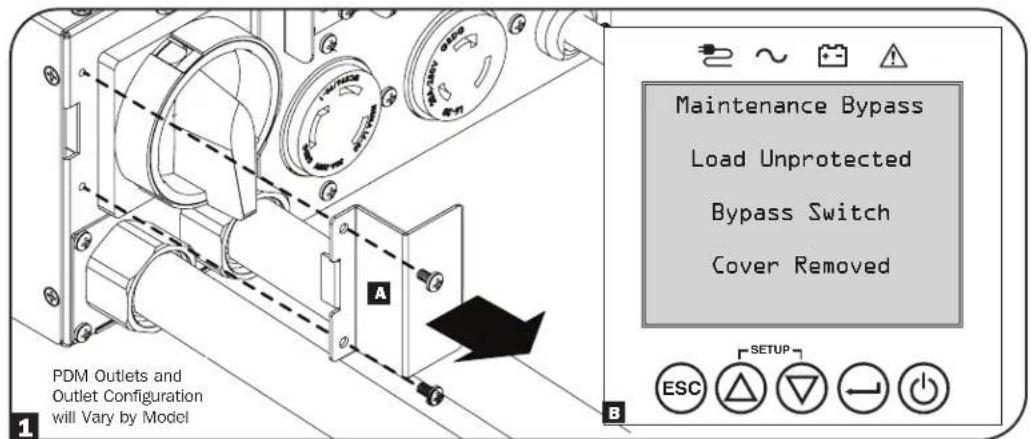
1 Remove the Bypass Switch Cover A. A warning will display on the UPS LCD panel B.
text_image
PDM Outlets and Outlet Configuration will Vary by Model A B Maintenance Bypass Load Unprotected Bypass Switch Cover Removed SETUP ESC2 The Bypass LED on the PDM will illuminate red when the UPS is not in the proper state to enter Maintenance Bypass mode. Do not attempt to switch to bypass when the red LED is illuminated, or the UPS load will be dropped.
Note: The UPS will only switch to Electronic Bypass mode if the line voltage and frequency is within the specified tolerance. See the UPS nameplate ratings for more information.
text_image
PDM Outlets and Outlet Configuration will Vary by Model3 If the Bypass LED on the PDM does not illuminate red, move the Maintenance Bypass Switch to the BYPASS position.
4 Press the ON/OFF button to shut down the UPS.
5 The UPS can safely be removed from the PDM and rack.
Note: When BYPASS is enabled, connected equipment will receive filtered AC mains power, but will not receive battery power in the event of a blackout.

text_image
PDM Outlets and Outlet Configuration will Vary by Model 3Replacement UPS Power Module Installation Procedure
1 Install the UPS to the rack and mate it with the PDM (refer to Mounting the UPS and Mounting the Power Module instructions for more information).
2 The UPS will power up. When it senses the Manual Bypass Switch is in the bypass position, the UPS will enter electronic Bypass Mode.
Note: If a remote management card is used, install it before mating the UPS to the PDM.
3 Using the LCD, configure the UPS settings to match the configurations made on the original UPS.
4 Turn the Manual Bypass Switch to the Normal Position.
5 Reinstall the Bypass Switch Cover. The maintenance bypass warning message will be cleared.
6 The UPS will remain in electronic Bypass Mode until the UPS is turned on via the LCD front panel display. To turn on the UPS, press and hold the ON button for 3 seconds.
Optional Connections
Your UPS will function properly without these connections.
1 USB and RS-232 Dry Contact Communications
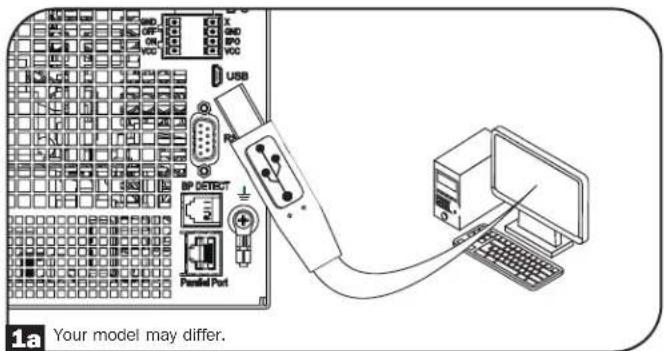
Use the included USB cable (see figure 1a) and/or RS-232 serial cable (see figure 1b) to connect the communication port of your computer to the communication port of your UPS. Install on your computer the Tripp Lite PowerAlert Software appropriate to your computer's operating system. Consult your PowerAlert manual for more information.
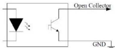
1c RS-232 dry contact communications are simple, but some knowledge of electronics is necessary to configure them. The RS-232 port's pin assignments are shown in the diagram. If the UPS battery is low, the UPS sends a signal by bridging pins 8 and 5. If utility power fails, the UPS sends a signal by bridging pins 1 and 5. To shut the UPS down remotely, short pin 3 to pin 9 for at least 4 seconds. Additional functions of these pins can be configured through the LCD or via Web management accessory card communication.
| PIN | Assignment Description | |
| RS-232 Dry Contact | ||
| 1 Utility Fail (Open Collector) | ||
| 2 UPS TxD | ||
| 3 UPS RxD Remote Shutdown (5-12V) | ||
| 4 Reserved Reserved | ||
| 5 GND GND | ||
| 6 Reserved Reserved | ||
| 7 | ||
| 8 Low Battery (Open Collector) | ||
| 9 + 12V (1KΩ source) | ||
| Rating and characteristics of pin 1 and 8 to GND | ||
| Parameter Value | Conditions | |
| Maximum collector voltage | 30V | |
| Maximum collector current | 10mA | |
| Maximum reverse collector voltage | -5V | |
| Maximum leakage current | 0.1μA | Collector voltage = 20V, pin function is not active |
| Typical voltage drop | 0.5V | Collector current = 5mA, pin function is active |
text_image
Open Collector GNDOpen Collector Circuit
text_image
USB R2 BP DETECT Parallel Port 1a Your model may differ.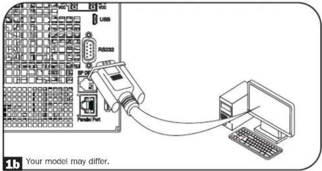
text_image
USB RS232 BP DR Pensal Port 1b Your model may differ.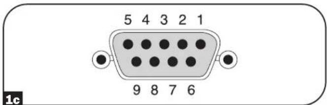
text_image
5 4 3 2 1 9 8 7 6 1cOptional Connections
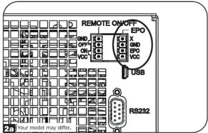
2 EPO Port Connection
This optional feature is only for those applications that require connection to a facility's Emergency Power Off (EPO) circuit. When the UPS is connected to this circuit, the UPS goes into fault standby. Connect the EPO port of your UPS (see 2a) to a user-supplied normally closed or normally open switch according to the circuit diagram (see 2b).
Note: The 4-pin terminal block supports wire gauges from 14-30 AWG with a strip length of 7 mm. The M2 terminal screws should be tightened between 0.22\~0.25 Nm. If a non-latching EPO switch is used, the EPO must be held for minimum of 1 second. This does not apply to a latching EPO switch.
text_image
REMOTE ON/OFF GND OFF ON VCC EPO X GND EPO VCC USB RS232 Your model may differ.
text_image
OPTION 1: USER SUPPLIED NORMALLY CLOSED SWITCH X- GND- EPO- VCC- NO CONNECTION N.C. SWITCH JUMPER OPTION 2: USER SUPPLIED NORMALLY OPEN SWITCH X- GND- EPO- VCC- NO CONNECTION NO CONNECTION N.O. SWITCHUPS state when asserting EPO with valid AC input present:
| AC Output LCD Screen Status LEDs Status USB Serial SNMP | |||||
| Off EPO Active Only | AC Input Indicator is On. | Off Off Off | |||
To restart the UPS after EPO assertion with valid AC input present:
- Verify that the EPO assertion has been removed or cleared.
- Press and hold the POWER ON/OFF button until it beeps. Now the UPS will start back up in one of the pre-configured normal operating modes.
UPS state when asserting EPO without valid AC input present (Battery Mode):
| AC Output LCD Screen Status LEDs Status USB Serial SNMP | |||||
| Off EPO Active Off | Off | Off | Off | ||
To restart the UPS after EPO assertion:
- Verify that the EPO assertion has been removed or cleared.
- Press and hold the POWER ON/OFF button until it beeps. Now the UPS will restart to either Battery Mode or the preconfigured normal operating mode (if AC power is present).
Optional Connections
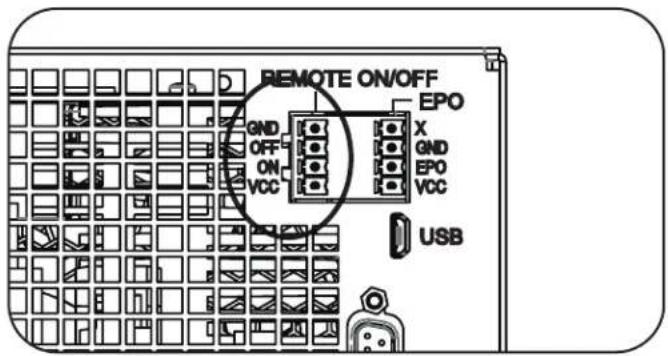
3 Remote ON/OFF Configuration
This feature is intended for switching the UPS to Bypass Mode for the Remote OFF configuration, or to Line Mode for the Remote ON configuration. The 4-pin terminal block supports wire gauges from 14-30 AWG with a strip length of 7 mm. The M2 terminal screws should be tightened between 0.22\~0.25 Nm.
Note: Before activating the Remote ON function, verify the AC input is present and valid.
text_image
REMOTE ON/OFF GND OFF ON VCC EPO X GND EPO VCC USB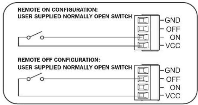
text_image
REMOTE ON CONFIGURATION: USER SUPPLIED NORMALLY OPEN SWITCH GND OFF ON VCC REMOTE OFF CONFIGURATION: USER SUPPLIED NORMALLY OPEN SWITCH GND OFF ON VCC4 External Battery Connection
Check the Model Specific Accessories section under
Overview for compatible battery packs and maximum quantities for your UPS system. Ensure that your battery pack matches the voltage listed next to your UPS battery connector. Adding external batteries will increase runtime as well as recharge time. See the battery pack owner's manual for complete installation and setup instructions. Make sure to attach the ground wire of the battery cable to the ground screw located near the DC connector first. Connect the DC connector and make sure it is fully inserted into their connectors prior to securing it with the thumbscrew. Small sparks may result during battery connection; this is normal. Do not connect or disconnect battery packs when the UPS is running on battery power.
text_image
Note: Reinstall the screw if the battery pack connector is be used to prevent loss of the screw. The Bypass Power Distribution Module cable has its own retention screw to secure connector to the manual bypass PDU. Your model may differ.IMPORTANT! In order for the runtime-remaining LCD and the software information screens to accurately predict runtime with external battery packs connected, you must configure any connected packs using the front panel LCD or Tripp Lite's External Battery Configuration software. See Configuring External Battery Packs section under Operations.

When installing an external battery pack, observe all external battery warnings in the Important Safety Instructions section of this manual and follow the external battery pack installation instructions.
Troubleshooting and Event Log
See the chart below for explanation of UPS faults and warnings that can be accessed via the Event Log feature via the LCD screen or PowerAlert software, as well as suggested solutions for each fault/warning.
| LCD Display Message LCD Display Header Text Comments | ||
| UPS Internal Errors/Faults: | ||
| Inverter Over Current ** FAULT | ** If issue persists, contact Tripp Lite. | |
| Inverter Over Current ** FAULT | ** If issue persists, contact Tripp Lite. | |
| Inverter Abnormal OCP ** FAULT | LT ** If issue persists, contact Tripp Lite. | |
| Inverter Bus Voltage ** FAULT | ** If issue persists, contact Tripp Lite. | |
| Internal Comm Lost ** FAULT | LT ** If issue persists, contact Tripp Lite. | |
| LCR Fault ** FAULT ** The UPS will not turn on. If issue persists, contact Tripp Lite. | ||
| Transaction Timeout ** FAULT ** If issue persists, contact Tripp Lite. | ||
| Emergency Shutdown ** FAULT ** If issue persists, contact Tripp Lite. | ||
| RTOS Fault ** FAULT ** If issue persists, contact Tripp Lite. | ||
| Low Power Supply ** FAULT ** If issue persists, contact Tripp Lite. | ||
| Manual Bypass Fault ** FAULT ** If issue persists, contact Tripp Lite. | ||
| PFC Precharge Fault ** FAULT ** If issue persists, contact Tripp Lite. | ||
| PFC Over Voltage ** FAULT ** If issue persists, contact Tripp Lite. | ||
| PFC Under Voltage ** FAULT ** If issue persists, contact Tripp Lite. | ||
| PFC Over Voltage ** FAULT ** If issue persists, contact Tripp Lite. | ||
| PFC Under Voltage ** FAULT ** If issue persists, contact Tripp Lite. | ||
| PFC Over Current ** FAULT ** If issue persists, contact Tripp Lite. | ||
| PFC Over Current ** FAULT ** If issue persists, contact Tripp Lite. | ||
| Header Mismatch ** ERROR ** If issue persists, contact Tripp Lite. | ||
| Fan Defective RPM Low | ** ERROR ** | If issue persists, contact Tripp Lite. |
| NVR Checksum Mismatch | ** ERROR ** | If issue persists, contact Tripp Lite. |
| NVR Invalid | ** ERROR ** | If issue persists, contact Tripp Lite. |
| RTC Oscillator Failed | ** ERROR ** | If issue persists, contact Tripp Lite. |
| RTC Corrupt Data | ** ERROR ** | If issue persists, contact Tripp Lite. |
| Logging Error | ** ERROR ** | If issue persists, contact Tripp Lite. |
| EEPROM Write Error | ** ERROR ** | If issue persists, contact Tripp Lite. |
| Fan Over Voltage | ** ERROR ** | If issue persists, contact Tripp Lite. |
| Fan Not Functioning ** ERROR ** If issue persists, contact Tripp Lite. | ||
| NVR Status Checksum | ** ERROR ** | If issue persists, contact Tripp Lite. |
| Load Sharing | ** ERROR ** | If issue persists, contact Tripp Lite. |
| Battery Health Failed | ** ERROR ** | If issue persists, contact Tripp Lite. |
| Double Queued Event | ** ERROR ** | If issue persists, contact Tripp Lite. |
| EEPROM Queue Overflow | ** ERROR ** | If issue persists, contact Tripp Lite. |
| Load/Temperature Related Errors/Faults: | ||
| Over Temperature | ** FAULT ** | In this mode, most power circuits should be off, thus lowering the temperature. Once in Fault Bypass mode, if the temperature exceeds the overtemperature threshold for 5 minutes, the unit will go to latched idle. |
| Overload | ** FAULT ** | The unit should automatically revert from fault bypass mode to ECO/Online (overload release) when the load is reduced to less than 95% consistently for 10 seconds. |
Troubleshooting and Event Log
| LCD Display Message LCD Display Header Text Comments | ||
| Battery/Charger Related Errors/Faults: | ||
| Max Battery Voltage ** FAULT ** If issue persists, contact Tripp Lite. | ||
| Min Battery Voltage ** FAULT ** If issue persists, contact Tripp Lite. | ||
| Max Battery Current ** FAULT ** If issue persists, contact Tripp Lite. | ||
| Charger Under Voltage ** ERROR ** The charger is working, but charge voltage is too low. | ||
| Charger Over Voltage ** ERROR ** The charger is working, but charge voltage is too high. | ||
| Charger Over Current ** ERROR ** The charger is working, but charge current is too high. | ||
| Charger Under Current ** ERROR ** The charger is working, but charge current is too low. | ||
| Charger Hardware Error ** ERROR ** If issue persists, contact Tripp Lite. | ||
| No Battery ** ERROR ** If there is no battery, only ECO to on-line transfers will occur. | ||
| Battery Over Voltage ** ERROR ** If issue persists, contact Tripp Lite. | ||
| Replace Battery ** ERROR ** | ||
| Low Battery Voltage ** ALERT ** | ||
| Low Battery % Shutdown ** ALERT ** | ||
| On Battery Timed SD | ** ALERT ** | |
| Other Warnings and Events: | ||
| Number of BP changed | ** ALERT ** | If this change is unexpected, check smart battery communications. |
| Emergency Power Off ** ALERT ** Check | Check | EPO switch status and settings. |
| Bypass PDM Detached | ** ALERT ** | |
| Energy Saving Shutdown | ** ALERT ** | |
| NonSmart Batt Age Alrt ** ALERT ** Non-Smart Battery may need replacement. | ||
| Int Batt Age Alert | ** ALERT ** | Internal battery may need replacement. |
| Ext Batt Age Alert | ** ALERT ** | External Smart Batt { S/N } may need replacement. |
Internal Battery Replacement

Battery Replacement Door: Under normal conditions, the original battery in your UPS will last several years. However, if batteries need to be replaced, the internal battery trays are hot-swappable. Battery replacement should be performed only by qualified service personnel. Refer to "Battery Warnings" in the Safety section. Replacement batteries can be found at tripplite.com/support/battery/index.cfm. See the chart below to find the right replacement battery for your UPS system:
| UPS Model Replacement Battery Cartridge | |
| SU5KRT3PM RBC58-3US | |
| SU5KRT3PMP RBC58-3US | |
| SU6KRT3PM RBC58-3US | |
| SU6KRT3PMP RBC58-3US |
See the following diagrams for battery removal and installation procedures.
1 Remove the six front screws from the front bezel, then remove the bezel from the UPS. Hang the bezel on the available hook.
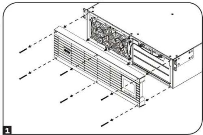
natural_image
Technical line drawing of a server rack unit with fan and ventilation ducts (no text or symbols)3 Open the battery door.
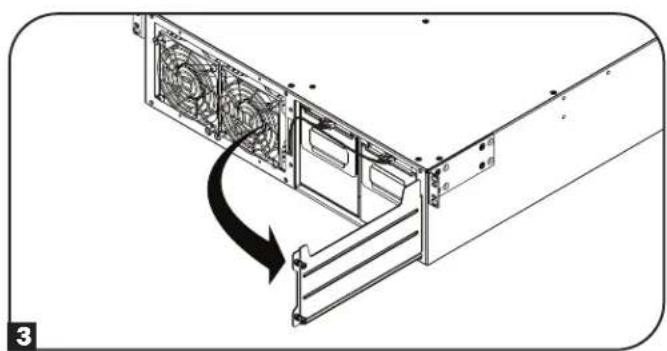
natural_image
Diagram of a server rack with fan blades and a directional arrow indicating rotation (no text or symbols)5 Once the communication cables have been disconnected. Remove both old battery trays from the UPS.
2 Loosen the two captive screws securing the battery door.
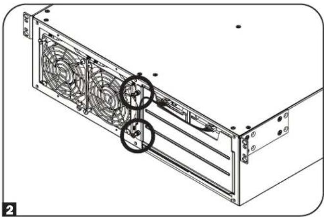
natural_image
Technical line drawing of a server rack with fan blades and mounting hardware (no text or symbols)4 Using the handles attached to each tray, pull out the old battery trays slightly and disconnect the communication cables.
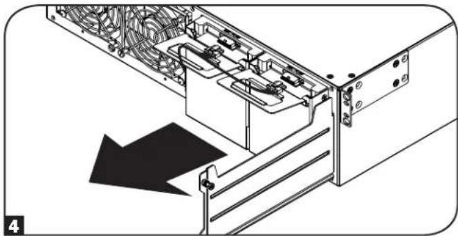
natural_image
Technical diagram of an electronic device showing internal components and a downward arrow indicating motion (no text or symbols present)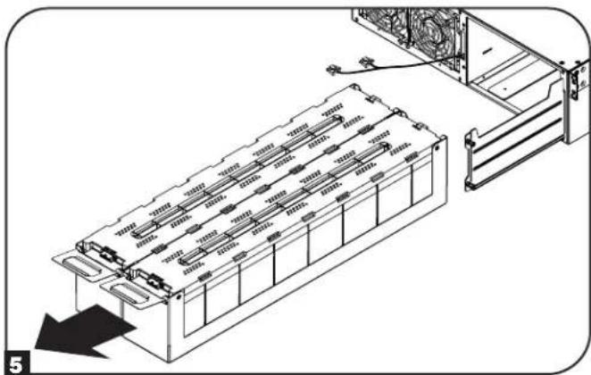
natural_image
Technical diagram of an electronic device chassis with internal components and a directional arrow indicating motion (no text or symbols present)Internal Battery Replacement
6 When installing the new replacement batteries, make sure the red and black DC connector end is facing towards the rear of the UPS and the communication port is facing toward the front of the UPS. Starting with the right side replacement battery pack tray, insert the battery pack tray completely into the unit, making sure it protrudes slightly from the UPS. Repeat for the left replacement battery pack tray.
Note: For better connector access, attach the communication cable connectors before the battery packs are fully inserted into the UPS.
7 Reconnect the battery communication cables to the battery trays and push them completely into the UPS.
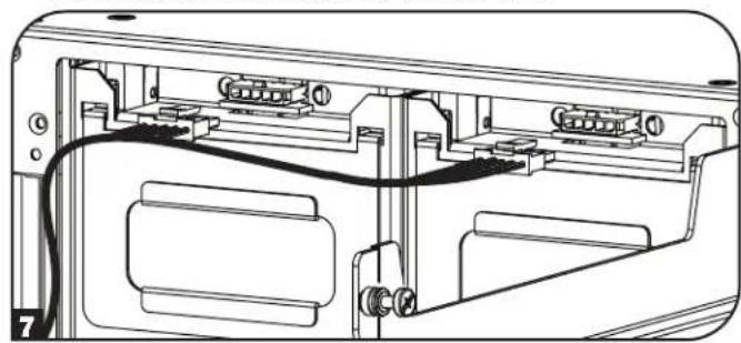
natural_image
Technical line drawing of a device rear panel with internal components and cable (no text or symbols)9 Reattach the front bezel to the UPS and secure with the screws removed in step 1.
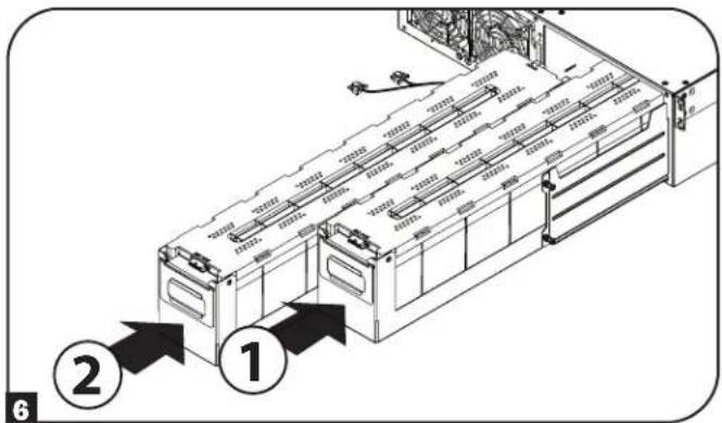
text_image
Technical diagram of a server rack with numbered annotations pointing to components8 Close the battery door and secure by tightening the captive screws.
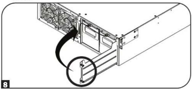
natural_image
Diagram of a computer tower drive showing fan array and cable insertion (no text or labels)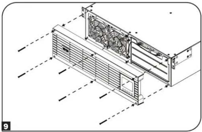
natural_image
Technical line drawing of a server rack with fan array and ventilation ducts (no text or symbols)Fan Replacement
Under normal conditions, the original fan installation will last several years. The fan assemblies are replaceable. Replacements can be found at tripplite.com/support.

CAUTION: The fan circuitry is not isolated from AC mains. Turn off power to the UPS prior to fan replacement. Fan replacement must be performed only by qualified electrical service personnel.

Before removing the fan assemblies, note the fan orientation. For proper installation and connectivity, the fans must remain in their original orientation.
1 Remove the six front screws from the front bezel, then remove the bezel from the UPS. Hang the bezel on the available hook.
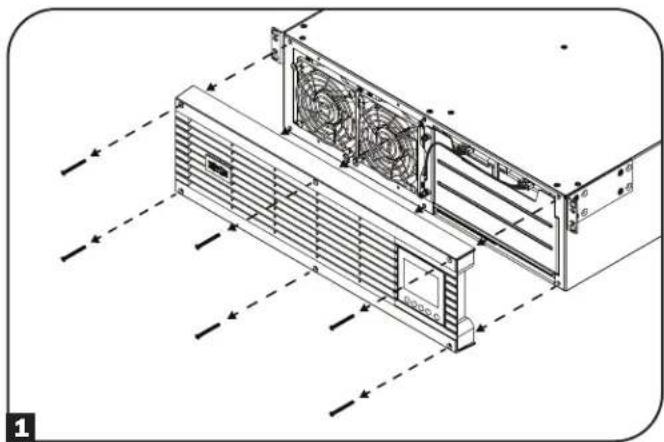
natural_image
Technical line drawing of an air conditioning unit with fan and ventilation ducts (no text or symbols)2 To replace the left-side fan or right-side fan, use a flat head screwdriver to remove the top-left screw and the bottom-right screw attached to each fan.
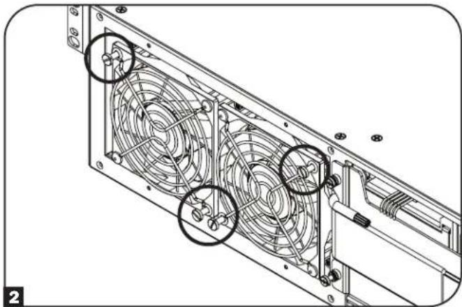
natural_image
Technical line drawing of a mechanical fan assembly with mounting brackets and mounting holes (no text or symbols)3 Disconnect the fan cable(s), located to the left of the fans.
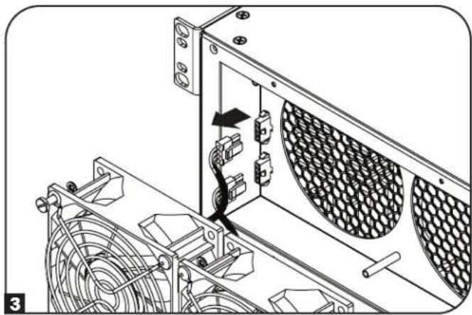
natural_image
Technical diagram of an air conditioning unit with cooling fan and fan blade assembly (no text or symbols)4 Install the replacement fan(s). Connect the cable(s) in the same order as in step 3 and secure the fan(s) to the UPS in the same location and orientation as in step 2.
5 Reattach the front bezel to the UPS and secure with the screws removed in step 1.
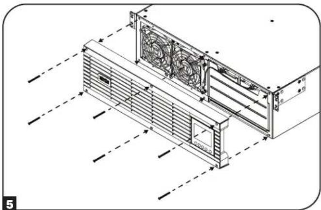
natural_image
Technical line drawing of a server rack unit with fan and ventilation ducts (no text or symbols)Storage and Service
Storage
First turn your UPS OFF: press the "OFF" switch to turn power off at the UPS outlets, then disconnect the power cord from the wall outlet. Next, disconnect all equipment to avoid battery drain. If you plan on storing your UPS for an extended period of time, fully recharge the UPS batteries once every three months by plugging the UPS into a live AC outlet and letting the UPS charge for 4-6 hours. If you leave your UPS batteries discharged for an extended period of time, they may suffer permanent loss of capacity.
Service
A variety of Extended Warranty and On-Site Service Programs are also available from Tripp Lite. For more information on service, visit tripplite.com/support. Before returning your product for service, follow these steps:
- Review the installation and operation procedures in this manual to ensure that the service problem does not originate from a misreading of the instructions.
-
If the problem continues, do not contact or return the product to the dealer. Instead, visit tripplite.com/support.
-
If the problem requires service, visit triplite.com/support and click the Product Returns link. From here you can request a Returned Material Authorization (RMA) number, which is required for service. This simple on-line form will ask for your unit's model and serial numbers, along with other general purchaser information. The RMA number, along with shipping instructions will be emailed to you. Any damages (direct, indirect, special or consequential) to the product incurred during shipment to Tripp Lite or an authorized Tripp Lite service center is not covered under warranty. Products shipped to Tripp Lite or an authorized Tripp Lite service center must have transportation charges prepaid. Mark the RMA number on the outside of the package. If the product is within its warranty period, enclose a copy of your sales receipt. Return the product for service using an insured carrier to the address given to you when you request the RMA.
Product Registration
Visit tripplite.com/warranty today to register your new Tripp Lite product. You'll be automatically entered into a drawing for a chance to win a FREE Tripp Lite product!* * No purchase necessary. Void where prohibited. Some restrictions apply. See website for details.
Regulatory Compliance Identification Numbers:
For the purpose of regulatory compliance certifications and identification, your Tripp Lite product has been assigned a unique series number. The series number can be found on the product nameplate label, along with all required approval markings and information. When requesting compliance information for this product, always refer to the series number. The series number should not be confused with the marketing name or model number of the product.
FCC Specifications for Models with FCC Class A Approval:
This device complies with part 15 of the FCC Rules. Operation is subject to the following two conditions: (1) This device may not cause harmful interference, and (2) this device must accept any interference received, including interference that may cause undesired operation.
Note: This equipment has been tested and found to comply with the limits for a Class A digital device, pursuant to part 15 of the FCC Rules. These limits are designed to provide reasonable protection against harmful interference when the equipment is operated in a commercial environment. This equipment generates, uses, and can radiate radio frequency energy and, if not installed and used in accordance with the instruction manual, may cause harmful interference to radio communications. Operation of this equipment in a residential area is likely to cause harmful interference in which case the user will be required to correct the interference at his own expense. The user must use shielded cables and connectors with this equipment. Any changes or modifications to this equipment not expressly approved by Tripp Lite could void the user's authority to operate this equipment.
EMC Specifications for Models with EMC Category C2 Approval (Select Models):
WARNING: This is a category C2 UPS product. In a residential environment, this product may cause radio interference, in which case the user may be required to take additional measures.
WEEE Compliance Information for Tripp Lite Customers and Recyclers (European Union)

Under the Waste Electrical and Electronic Equipment (WEEE) Directive and implementing regulations, when customers buy new electrical and electronic equipment from Tripp Lite they are entitled to:
- Send old equipment for recycling on a one-for-one, like-for-like basis (this varies depending on the country)
- Send the new equipment back for recycling when this ultimately becomes waste
FCC Part 68 Notice (United States Only)
If your Modem/Fax Protection causes harm to the telephone network, the telephone company may temporarily discontinue your service. If possible, they will notify you in advance. If advance notice isn't practical, you will be notified as soon as possible. You will be advised of your right to file a complaint with the FCC. Your telephone company may make changes in its facilities, equipment, operations or procedures that could affect the proper operation of your equipment. If it does, you will be given advance notice to give you an opportunity to maintain uninterrupted service. If you experience trouble with this equipment's Modem/Fax Protection, please visit tripplite.com/support for repair/warranty information. The telephone company may ask you to disconnect this equipment from the network until the problem has been corrected or you are sure the equipment is not malfunctioning. There are no repairs that can be made by the customer to the Modem/Fax Protection. This equipment may not be used on coin service provided by the telephone company. Connection to party lines is subject to state tariffs. (Contact your state public utility commission or corporation commission for information.)
UPS and Battery Recycling

Please recycle Tripp Lite Products. The batteries used in Tripp Lite products are sealed Lead-Acid batteries. These batteries are highly recyclable. Please refer to your local codes for disposal requirements.
You can call Tripp Lite for recycling info at +1.773.869.1234.
You can go the Tripp Lite Website for up-to-date information on recycling the batteries or any Tripp Lite product. Please follow this link: triplite.com/en/support/recycling-program.cfm
Tripp Lite has a policy of continuous improvement. Specifications are subject to change without notice. Photos and illustrations may differ slightly from actual products.

text_image
TRIPP·LITE
Manufacturing Excellence.
1111 W. 35th Street, Chicago, IL 60609 USA • tripplite.com/support
21-09-124 9339A0 RevD
SU5KRT3PM, SU6KRT3PM
(Número de Serie: AG-0357)
English 1 • Français 81 • Русский 121
1111 W. 35th Street, Chicago, IL 60609 EE UU • tripplite.com/support
natural_image
Technical line drawing of a server rack unit and its corresponding two-tier mechanical bracket (no text or symbols)natural_image
Simple line drawing of a cable with two leads and a connector (no text or symbols)natural_image
Technical line drawing of a server rack unit with fan and ventilation ducts (no text or symbols)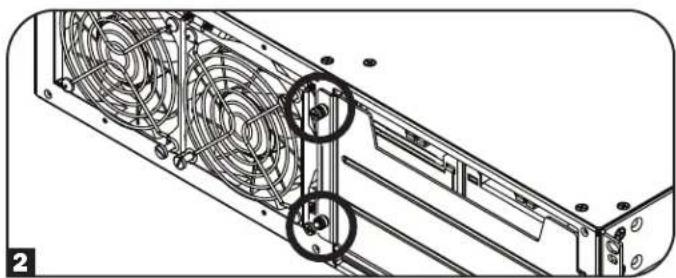
natural_image
Technical line drawing of a server rack with fan blades and mounting holes (no text or symbols)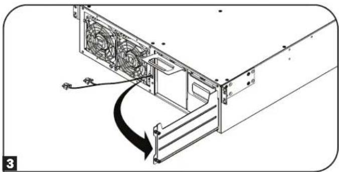
natural_image
Diagram of a computer tower drive showing fan arrangement and cooling mechanism (no text or symbols)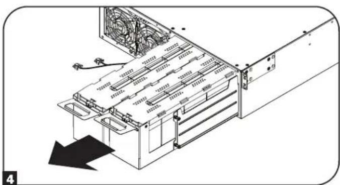
natural_image
Technical diagram of a server rack with cooling fans and ventilation ducts, showing internal components without any text or symbols.Instalación
text_image
Technical diagram of a server rack with numbered annotations pointing to components
natural_image
Technical line drawing of a computer case with internal components and cable (no text or symbols)
natural_image
Diagram of a computer tower with fan blades and cable, showing internal structure without any text or symbols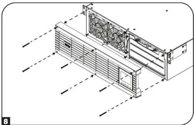
natural_image
Technical line drawing of a server rack unit with fan and ventilation ducts (no text or symbols)Instalación
Instalación en Rack
text_image
E E D F 3natural_image
Technical line drawing of a mechanical assembly with mounting flanges and a vertical panel (no text or symbols)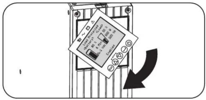
text_image
Load Processor Control 80 V 4 MΩ 80 V 400 V Load Control 80 V 4 MΩ 80 V 400 V Load Control 80 V 4 MΩ 80 V 400 Vnatural_image
Line drawing of a plug inserted into an electrical socket (no text or symbols)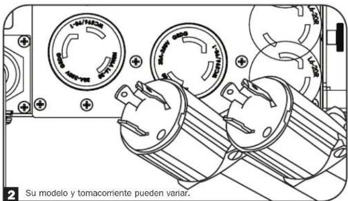
text_image
Language ► English French Spanish Russian Select Apply ESC SETUPOperaciones
text_image
Power Strategy ► Auto-Adaptive Max Efficiency Max Quality Freq. Regulation Freq. Conv. To 60Hz Freq. Conv. To 50Hz Back Select Apply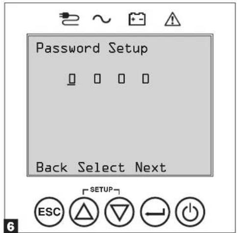
text_image
Password Setup Back Select Next ESC SETUP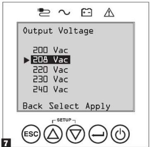
text_image
Output Voltage 200 Vac ▶208 Vac 220 Vac 230 Vac 240 Vac Back Select Apply ESC SETUPOperaciones
text_image
Audible Alarm ▶ Enabled Disabled Back Select Apply ESC SETUPOperaciones
natural_image
Technical line drawing of a server rack unit with fan and ventilation ducts (no text or symbols)natural_image
Diagram of a server rack with fan blades and a scroll arrow indicating rotation (no text or symbols)natural_image
Technical line drawing of a server rack with fan blades and mounting hardware (no text or symbols)natural_image
Technical diagram of an electronic device showing internal components and a downward arrow indicating motion (no text or symbols present)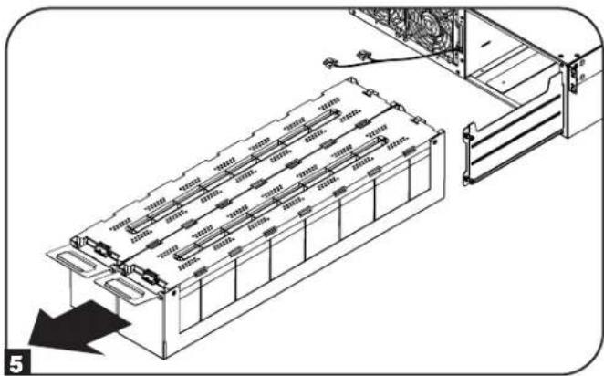
natural_image
Technical diagram of an electronic device chassis with labeled components and a directional arrow indicating motion (no text or symbols present)natural_image
Technical line drawing of a computer case with internal components and cable (no text or symbols)text_image
Technical diagram of a server rack with numbered annotations pointing to componentsnatural_image
Diagram of a computer tower with a cable inserted into the frame, showing fan arrangement and a magnified inset (no text or symbols)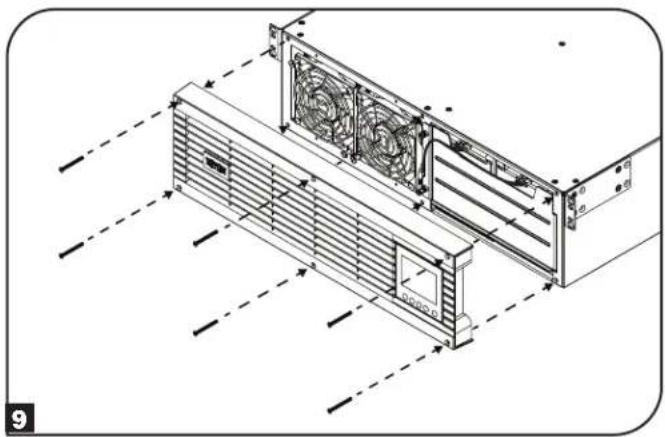
natural_image
Technical line drawing of a server rack with fan cooling system (no text or symbols)natural_image
Technical line drawing of a server rack with fan and ventilation ducts (no text or symbols)natural_image
Technical line drawing of an air conditioning unit with cooling fan and fan blade (no text or symbols)natural_image
Technical line drawing of a server rack with multiple fans and mounting hardware (no text or symbols)natural_image
Technical line drawing of a server rack with fan and ventilation ducts (no text or symbols)1111 W. 35th Street, Chicago, IL 60609 EE UU • tripplite.com/support
21-09-124 9339A0 RevD
SU5KRT3PM, SU6KRT3PM
1111 W. 35th Street, Chicago, IL 60609 USA • tripplite.com/support
natural_image
Technical line drawing of a server rack unit and its corresponding two-framed mechanical bracket (no text or symbols)natural_image
Simple line drawing of a热线 rod with a coiled cable and two terminal leads (no text or symbols)natural_image
Technical line drawing of a server rack unit with fan and ventilation ducts (no text or symbols)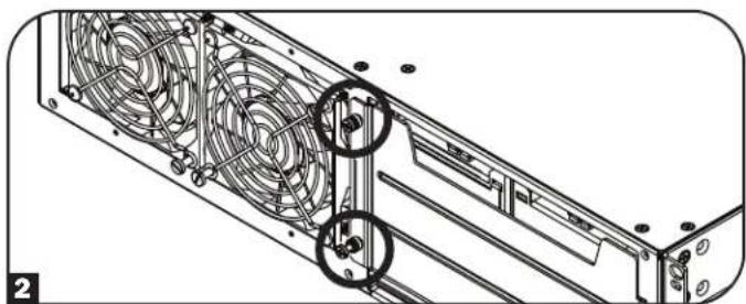
natural_image
Technical line drawing of a server rack with fan blades and mounting holes (no text or symbols)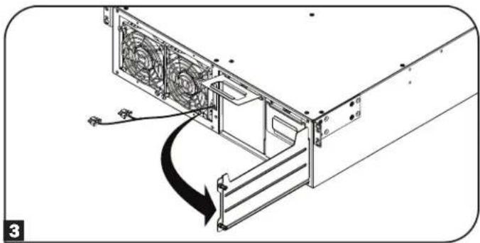
natural_image
Technical line drawing of a computer tower with fan blades and ventilation slots, showing a curved arrow indicating motion (no text or symbols)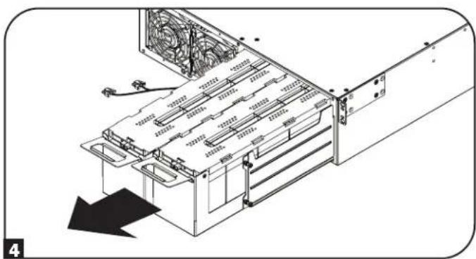
natural_image
Technical diagram of a server rack with cooling fans and ventilation ducts, showing internal structure without any text or symbolsInstallation
text_image
Technical diagram of a server rack with numbered annotations pointing to internal components and ventilation system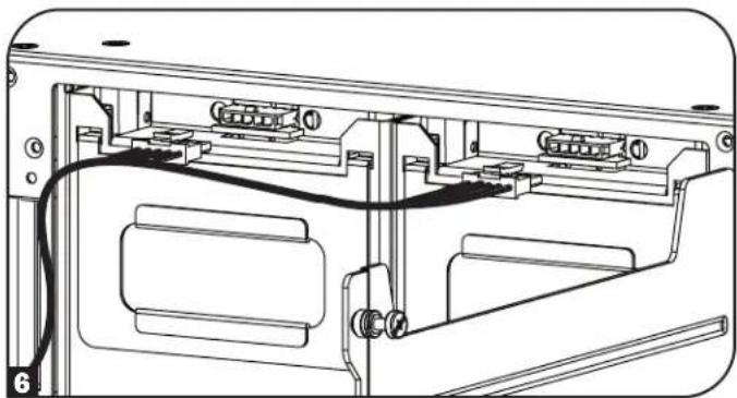
natural_image
Technical line drawing of a computer case with internal components and wiring (no text or symbols)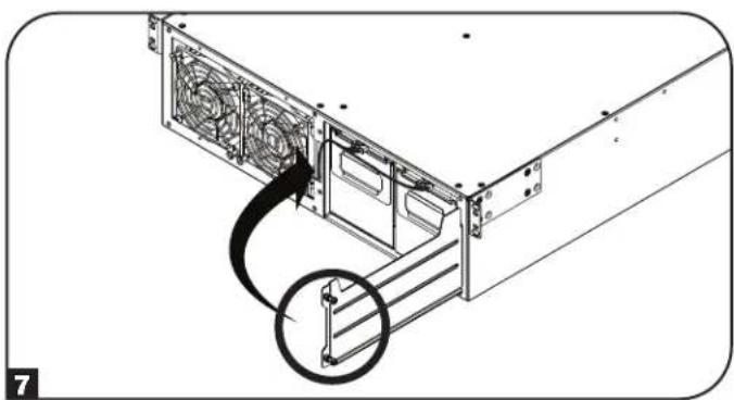
natural_image
Diagram of a computer tower with fan blades and cable, showing internal structure without any text or symbols
natural_image
Technical line drawing of a server rack unit with fan and ventilation ducts (no text or symbols)Installation
Montage en bâti
text_image
Technical diagram of a mechanical assembly with labeled components A and B, showing structural connections.text_image
E E D F 3natural_image
Technical line drawing of a mechanical assembly with mounting flanges and a vertical panel (no text or symbols)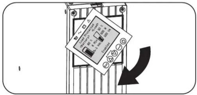
text_image
Load Processor 80 V 4 Min 300 W Load 4 Min 300 W Load 4 Min 300 W Load 4 Min 300 W Load 4 Min 300 W Load 4 Min 300 W Load 4 Min 300 W Load 4 Min 300 W Load 4 Min 300 W Load 4 Min 300 W Load 4 Min 300 W Log 1.5V Log 1.5V Log 1.5V Log 1.5V Log 1.5V Log 1.5V Log 1.5V Log 1.5V Log 1.5V Log 1.5V Log 1.5V Log 1.5V Log 1.5V Log 1.5V Log 1.5V Load 1.5V Load 1.5V Load 1.5V Load 1.5V Load 1.5V Load 1.5V Load 1.5V Load 1.5V Load 1.5V Load 1.5V Load 1.5V Load 1.5V Load 1.5V Load 1.5V Load 2.5V Load 2.5V Load 2.5V Load 2.5V Load 2.5V Load 2.5V Load 2.5V Load 2.5V Load 2.5V Load 2.5V Load 2.5V Load 2.5V Load 2.5V Load 2.5V Load 2.7V Load 2.7V Load 2.7V Load 2.7V Load 2.7V Load 2.7V Load 2.7V Load 2.7V Load 2.7V Load 2.7V Load 2.7V Load 2.7V Load 2.7V Load 2.7V Load 2.7Vnatural_image
Line drawing of a plug inserted into an electrical socket (no text or symbols)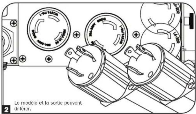
text_image
Language ► English French Spanish Russian Select Apply ESC SETUPOpérations
text_image
Power Strategy ► Auto-Adaptive Max Efficiency Max Quality Freq. Regulation Freq. Conv. To 60Hz Freq. Conv. To 50Hz Back Select Apply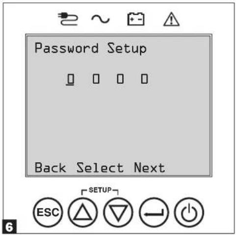
text_image
Password Setup Back Select Next ESC SETUP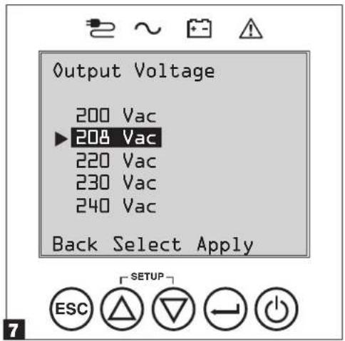
text_image
Output Voltage 200 Vac ▶208 Vac 220 Vac 230 Vac 240 Vac Back Select Apply ESC SETUPOpérations
text_image
Audible Alarm ▶ Enabled Disabled Back Select Apply ESC SETUPOpérations
natural_image
Technical line drawing of a server rack unit with fan array and ventilation ducts (no text or symbols)natural_image
Diagram of a computer tower drive showing fan arrangement and rotation arrow (no text or symbols)natural_image
Technical line drawing of a server rack with fan blades and mounting hardware (no text or symbols)natural_image
Technical diagram of a computer drive with fan and cooling unit (no text or symbols)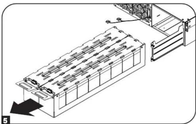
natural_image
Technical illustration of an internal battery pack assembly with mounting bracket and load mechanism (no text or symbols)natural_image
Technical line drawing of a device rear panel with internal components and cable (no text or symbols)text_image
Technical diagram of a server rack with numbered annotations pointing to componentsnatural_image
Diagram of a computer tower drive showing fan array and cable connection (no text or symbols)
natural_image
Technical line drawing of a server rack with fan blades and ventilation ducts (no text or symbols)natural_image
Technical line drawing of an air conditioning unit with fan and cooling fins (no text or symbols)natural_image
Technical line drawing of an air conditioning unit with cooling fan and fan blade (no text or symbols)natural_image
Technical line drawing of a server rack with multiple fans and mounting hardware (no text or symbols)natural_image
Technical line drawing of a server rack with fan and ventilation ducts (no text or symbols)1111 W. 35th Street, Chicago, IL 60609 USA • tripplite.com/support
21-09-124 9339A0 RevD
SU5KRT3PM, SU6KRT3PM
1111 W. 35th Street, Chicago, IL 60609 USA - tripplite.com/support
natural_image
Technical line drawing of a server rack unit with fan and ventilation ducts (no text or symbols)
natural_image
Technical line drawing of a server rack with fan blades and mounting holes (no text or symbols)
natural_image
Diagram of a computer tower drive showing fan arrangement and cable connection (no text or symbols)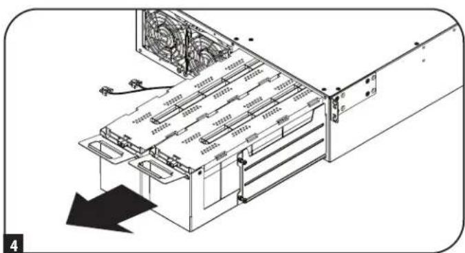
natural_image
Diagram of a server rack with cooling fans and ventilation ducts, showing internal components without any text or symbols.Установка
text_image
Technical diagram of a server rack with numbered annotations pointing to components
natural_image
Technical line drawing of a device rear panel with connectors and wiring (no text or symbols)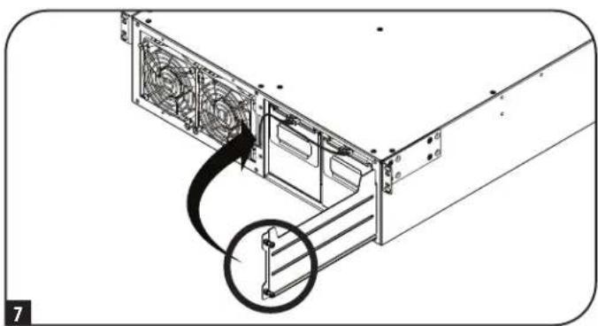
natural_image
Diagram of a computer tower rear panel with a cable and fan, showing internal components without any text or symbols.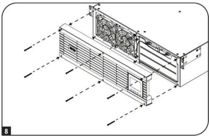
natural_image
Technical line drawing of a server rack unit with fan and ventilation ducts (no text or symbols)Установка
Монтаж в стойку
text_image
Technical diagram showing structural components labeled C and B, with annotations for assembly or installation details.Установка
text_image
E E D F 3natural_image
Technical line drawing of a mechanical assembly with mounting flanges and a vertical panel (no text or symbols)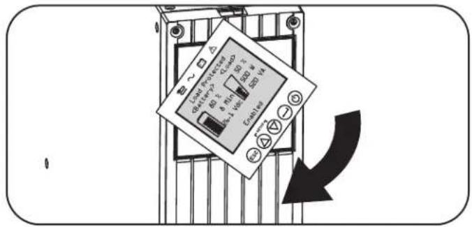
text_image
Load Power Sensor 80 V 6 Min 300 W 3.4 V Enable Down Downnatural_image
Line drawing of a plug inserted into an electrical socket (no text or symbols)
text_image
1-5V/14CM 1-5V/14CM 1-5V/14CM 1-5V/14CM 1-5V/14CM 1-5V/14CM 1-5V/14CM 1-5V/14CM 1-5V/14CM 1-5V/14CM 1-5V/14CM 1-5V/14CM 2. Ваша модель и розетки могут иметь отличия.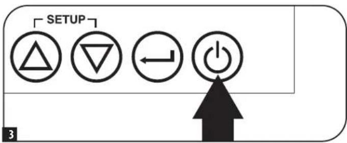
text_image
SETUP 3
text_image
Language ► English French Spanish Russian Select Apply ESC SETUPЭксплуатация
text_image
Power Strategy ► Auto-Adaptive Max Efficiency Max Quality Freq. Regulation Freq. Conv. To 60Hz Freq. Conv. To 50Hz Back Select Apply
text_image
Password Setup Back Select Next ESC SETUP
text_image
Output Voltage 200 Vac ▶208 Vac 220 Vac 230 Vac 240 Vac Back Select Apply ESC SETUPЭксплуатация
text_image
Audible Alarm ▶ Enabled Disabled Back Select Apply ESC SETUPЭксплуатация
natural_image
Technical line drawing of a server rack with fan and ventilation ducts (no text or symbols)natural_image
Diagram of a server rack with fan blades and a curved arrow indicating rotation (no text or symbols)natural_image
Technical line drawing of a server rack with fans and drive bays (no text or symbols)natural_image
Diagram of an internal server rack with cooling fans and ventilation ducts, showing a black arrow indicating direction (no text or symbols present)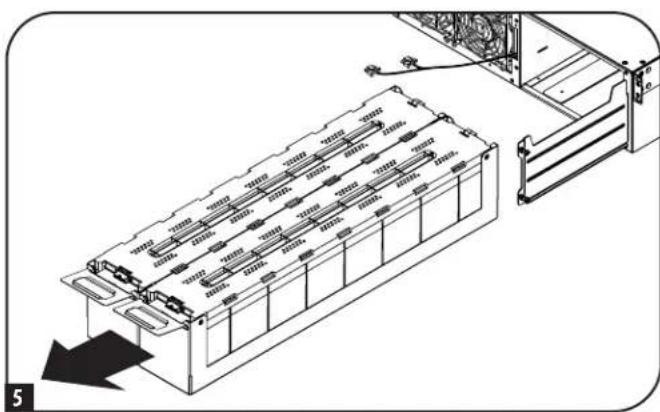
natural_image
Technical diagram of an electronic device chassis with internal components and a directional arrow indicating motion (no text or symbols present)natural_image
Technical line drawing of a device rear panel with internal components and cable routing (no text or symbols)text_image
Technical diagram of a server rack with numbered annotations pointing to componentsnatural_image
Diagram of a computer tower drive showing fan array and cable insertion (no text or symbols)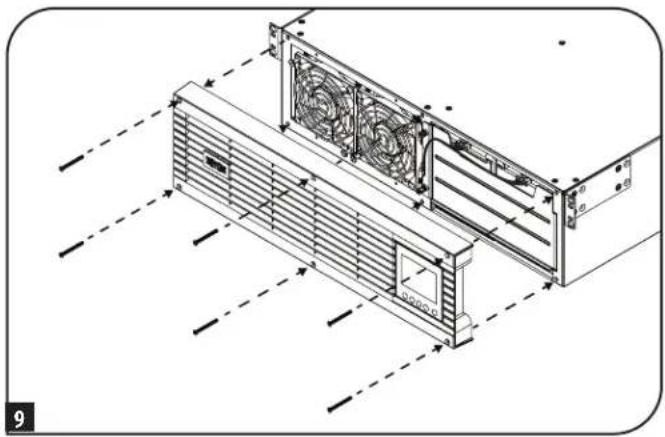
natural_image
Technical line drawing of a server rack with fan array and ventilation ducts (no text or symbols)Замена вентиляторов
natural_image
Technical line drawing of a server rack unit with fan and ventilation ducts (no text or symbols)natural_image
Technical line drawing of a mechanical fan assembly with mounting brackets and mounting holes (no text or symbols)natural_image
Technical line drawing of an air conditioning unit with fan and cooling fan assembly (no text or symbols)natural_image
Technical line drawing of a server rack unit with fan and ventilation ducts (no text or symbols)1111 W. 35th Street, Chicago, IL 60609 USA • tripplite.com/support