508346 - Audio/video converter Intellinet - Free user manual and instructions
Find the device manual for free 508346 Intellinet in PDF.


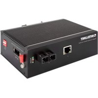
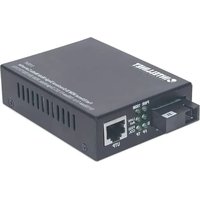
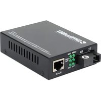
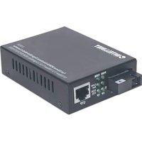
| Product Type | Audio/Video Media Converter (Ethernet to Fiber Media Converter) |
| Brand | Intellinet |
| Model | 508346 |
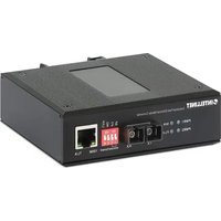
| RJ45 Port | 1 port 10/100/1000 Mbps, max distance 100 m (Cat5e cable or higher) |
| Fiber Optic Port | 1 single-mode 1000Base-LX port, SC connector, max distance 20 km |
| Power | Dual redundant DC input 12-58 V via terminal block |
| Mechanical | Metal housing, IP40 rating, DIN rail or desktop mounting |
| LED Indicators | RJ45 port (activity, speed), power (P), fiber optic (O), alarm (A), management (NMC) |
| DIP Switch | 4 positions: C/D (console/data), LGY (legacy system), VLAN (unused), RST (manual reset) |
| Management | Integrated console/RS232/RS485 port, NMC indicator |
| Alarm Function | Under-voltage alarm (<12V), over-voltage alarm (>58V), signal loss alarm (dying gasp) |
| Maximum Fiber Distance | 20 km (single-mode) |
| Operating Temperature | -40°C to 75°C (industrial) |
| Installation | On DIN rail (35 mm) or flat surface (25 mm ventilation) |
| Grounding | Chassis ground terminal for protection against voltage spikes |
| Fiber Wavelength | 1310 nm (typical for 1000Base-LX) |
| Compliance | CE (2014/30/EU and 2014/35/EU) |
Frequently Asked Questions - 508346 Intellinet
User questions about 508346 Intellinet
0 question about this device. Answer the ones you know or ask your own.
Ask a new question about this device
Download the instructions for your Audio/video converter in PDF format for free! Find your manual 508346 - Intellinet and take your electronic device back in hand. On this page are published all the documents necessary for the use of your device. 508346 by Intellinet.
USER MANUAL 508346 Intellinet
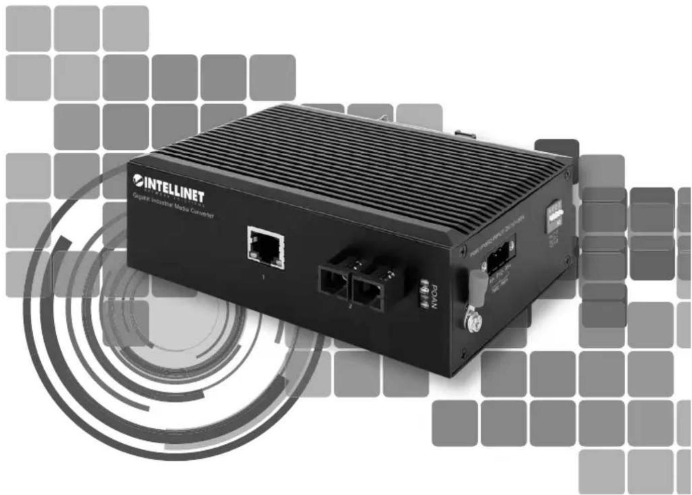
Model 508346 (IMCI-SMSCG20KM)

Important: Read before use. • Importante: Leer antes de usar.
For additional benefits:
Scan to register your product warranty

or go to: register.intellinet-network.com/r/508346
Media converters connect two Ethernet networks over a longer distance using fiber optic cable.
For specifications, visit intellinetnetwork.com. Register your product at register.intellinet-network.com/r/508346 or scan the QR code on the cover.
Features
• One 10/100/1000 RJ45 port supporting a maximum distance of 100 m (300 ft.)
• One 1000Base-LX fiber SC single-mode port supporting a maximum distance of 20 km (12.4 mi.)
- IP40 slim-type metal housing to withstand harsh industrial conditions
- Option for DIN-rail installation
- Two redundant DC inputs (12 - 58 V) with I/O terminal block

Connections
Twisted Pair - RJ45
Connect the UTP port of the media converter to an RJ45 port on the network (e.g., to an Ethernet switch). Cat5e or better cabling is recommended.
Fiber Optic
As shown, two fiber optic cables need to be connected between two ideally identical media converters.
Make a connection from Media Converter 1 TX to Media Converter 2 RX, and from Media Converter 1 RX to Media Converter 2 TX. Maximum length and fiber cable specification depend on the model. (See Models.)
Example
![graph TD A["MEDIACONVERTER 1"] -->|TX RX RJ45| B["MEDIA CONVERTER2"] C["ETHERNET 1"] -->|TWISTED PAIR| B D["ETHERNET 2"] -->|TWISTED PAIR| B B -->|OPTICAL FIBER| E["TWISTED PAIR"] E --> A](/content/2026/04/684619/images/ae0619eb42e6d73b12a9b3297f8f61aa36d15b9c1e81bed4c87e5dac88852658.jpg)

Front panel
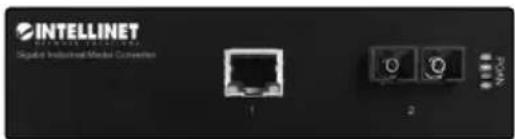
| Item LED Color | Status Description | |||
| RJ45 Port | Port activity Green | Flashing Sending or receiving data. | ||
| On Port is connected. | ||||
| Off Port is not connected. | ||||
| Speed Yellow | On 1000 Mbps speed. | |||
| Off 10/100 Mbps speed. | ||||
| P — Power | Power and power-supply-under-voltage alarm (priority of under-voltage alarm is higher than power LED) | Green | Flashing every 1s | Equipment power supply is lower than the lower limit of the input range of DC 12 V, indicating an under-voltage alarm. |
| On Power channel is powered. | ||||
| Off Power channel is not powered. | ||||
| O — Optical Fiber Port | Fiber port and power supply overvoltage alarm (priority for overvoltage alarm is higher than fiber port Link/Act LED) | Green | Flashing every 0.5s | The power supply of the device exceeds the upper limit of the input range of DC 58 V, indicating an overvoltage alarm. |
| On Fiber port is connected. | ||||
| Off Fiber port is not connected. | ||||
| Flashing Sending or receiving data. | ||||
| A — Alarm | Device alarm and data transmission indicator | Red | Flashing | Console/RS232/RS485 port is sending data (LED flashes to the rhythm of data being sent). |
| On An issue has been detected (temperature, dying gasp, etc.). | ||||
| Off No alarm issue detected. | ||||
| N — NMC | Management indicator and data receiving | Green | Flashing | Console/RS232/RS485 port is receiving data (LED flashes to the rhythm of data being received). |
| On Module embedded and initialization is complete. | ||||
| Off No embedded module. | ||||

Side Panel

A—Grounding Chassis
ATTENTION: When installing unit, connect the chassis ground first; when uninstalling unit, disconnect chassis ground last.
Wire the grounding terminal to an earth-grounding object to prevent power spikes.
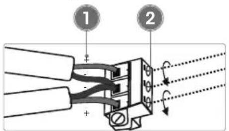
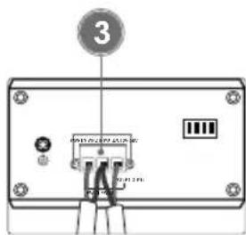
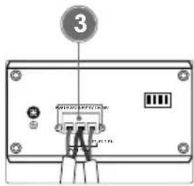
B—Terminal Block Installation
NOTE: Ensure all power is off/disconnected before beginning!
1 Loosen appropriate screws. Insert bare power-supply wires into appropriate terminal slots (positive wire into positive slot; negative wire into negative slot).
2 Tighten appropriate screws to secure wires.
3 Install block into the device and tighten screws.
C—DIP Switch
| Switch Position Description | ||
| 1 — C/DConline/Data selector | On Enable remote PD reset function. | |
| Off Turn off remote PD reset function. | ||
| 2 — LGYLegacy | On Supports standard and non-standard PD power supply. | |
| Off Only supplies power to standard PD; non-standard PD power supplies not supported. | ||
| 3 — VLANUnused | ||
| 4 — RSTManual Reset | On Reset the remote PD device after 24 hours. | |
| Off Release reset. | ||

Placement
Desktop Installation
Prior to use, place/position the device:
- on a level surface with at least 25 mm (approx. 1") of clearance for ventilation;
- away from sources of electrical noise: radios, transmitters, broadband amplifiers;
- within 100 m (approx. 328') of network devices it's to be connected to.
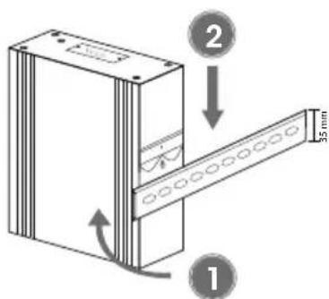
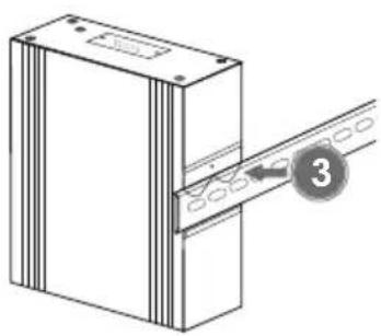
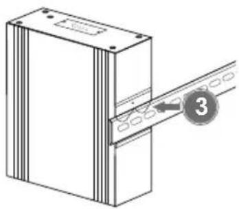
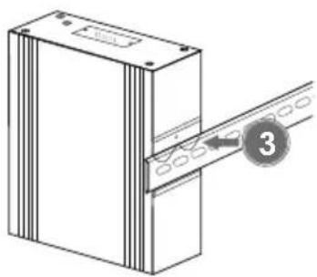
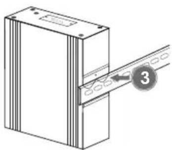
DIN-Rail Installation
1 Angle spring of mounting clip over top lip of DIN rail.
2 Push device down till clip clicks onto rail.
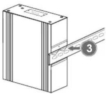
3 Ensure installation is stable.
C—DIP-Switch
C—Interruttore DIP
WASTE ELECTRICAL & ELECTRONIC EQUIPMENT
DISPOSAL OF ELECTRIC AND ELECTRONIC EQUIPMENT
(Applicable In The European Union And Other European Countries With Separate Collection Systems)
ENGLISH: This symbol on the product or its

packaging means that this product must not be treated as unsorted household waste. In accordance with EU Directive 2012/19/EU on
Waste Electrical and Electronic Equipment (WEEE), this electrical product must be disposed of in accordance with the user's local regulations for electrical or electronic waste. Please dispose of this product by returning it to your local point of sale or recycling pickup point in your municipality. DEUTSCH: Dieses auf dem Produkt oder der Verpackung angebrachte Symbol zeigt an, dass dieses Produkt nicht mit dem Hausmüll entsorgtwerden darf. In Übereinstimmung mit der Richtlinie 2012/19/EU des Europäischen Parlaments und FRANÇAIS : Ce symbole sur le produit ou son emballage signifie que ce produit ne doit pas être traité comme un déchet ménager. Conformément à la Directive 2012/19/EU sur les déchets d'équipements électriques et électroniques (DEEE), ce produit POLSKI: Jeśli na produkcie lub jego opakowaniu umieszczono ten symbol, wówczas w czasie utylizacji nie wolno wyrzucać tego produktu wraz z odpadami komunalnymi. Zgodnie z Dyrektywą Nr 2012/19/EU w sprawie zużytego sprzętu elektrycznego i elektronicznego (WEEE), niniejszego produktu elektrycznego nie wolno usuwać jako nie posortowanego odpadu komunalnego. Prosimy o usuniecie niniejszego produktu poprzez jego zwrot do punktu zakupu lub oddanie do miejscowego komunalnego punktu zbiórki
This equipment has been tested and found to comply with the limits for a Class B digital device, pursuant to Part 15 of Federal Communications Commission (FCC) Rules. These limits are designed to provide reasonable protection against harmful interference in a residential installation. This equipment generates, uses and can radiate radio frequency energy, and if not installed and used in accordance with the instructions may cause harmful interference to radio communications. However, there is no guarantee that interference will not occur in a particular installation. If this equipment does cause harmful interference to radio or television reception, which can be determined by turning the equipment off and on, the user is encouraged to try to correct the interference by one or more of the following measures: reorient or relocate the receiving antenna; increase the separation between the equipment and the receiver; connect the equipment to an outlet on a circuit different from the receiver; or consult the dealer or an experienced radio/TV technician for help.
CE
ENGLISH : This device complies with the requirements of CE 2014/30/EU and / or 2014/35/EU. The Declaration of Conformity for is available at:
support.intellinet-network.com/barcode/508346



North America
IC Intracom America
550 Commerce Blvd
Oldsmar, FL 34677, USA
Asia & Africa
IC Intracom Asia
4-E, No. 77, Sec. 1, Xintai 5th Rd. Xizhi Dist., New Taipei City 221, Taiwan
Europe
IC Intracom Europe
Löhbacher Str. 7, D-58553
Halver, Germany
All trademarks and trade names are the property of their respective owners.
All trademarks and trade names are the property of their respective owners. © IC Intracom. All rights reserved. Intellinet Network Solutions is a trademark of IC Intracom, registered in the U.S. and other countries.
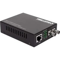
Brand : Intellinet
Model : 508346
Category : Audio/video converter