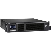
UPS1RM2U1500 - Uninterruptible power supply V7 - Free user manual and instructions
Find the device manual for free UPS1RM2U1500 V7 in PDF.


| Product Type | Uninterruptible Power Supply (UPS) |
| Brand | V7 |
| Model | UPS1RM2U1500 |
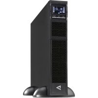
| Form Factor | 2U rackmount (rack or tower) |
| Dimensions (approx.) | 88 x 438 x 600 mm (H x W x D) |
| Weight (approx.) | 25 kg |
| Nominal Input Voltage | 230 VAC (EU model) or 120 VAC (US model) |
| Input Voltage Range | 160-300 VAC (EU model) or 85-150 VAC (US model) |
| Output Voltage | Adjustable: 208/220/230/240 VAC (EU) or 110/115/120/127 VAC (US) |
| Apparent Power | 1500 VA |
| Battery Type | Lead-acid, internal, replaceable |
| Typical Runtime | Variable depending on load; about 10-30 min at full load |
| Connectivity | USB port, RS-232 port, SNMP card slot |
| Main Functions | Automatic Voltage Regulation (AVR), programmable outlets, Emergency Power Off (EPO), network and telephone line protection |
| Display | LCD screen with icons and error codes |
| Audible Alarms | Low battery, overload, error, etc. |
| Safety | Overload, short-circuit, and electrostatic discharge protection |
| Maintenance | Battery replacement by a qualified technician; cleaning with a dry cloth |
| Operating Temperature | 0°C to 40°C |
| Storage Temperature | -25°C to 45°C |
| Included Software | ViewPower (monitoring and management) |
| Spare Parts | Replacement batteries available |
Frequently Asked Questions - UPS1RM2U1500 V7
User questions about UPS1RM2U1500 V7
0 question about this device. Answer the ones you know or ask your own.
Ask a new question about this device
Download the instructions for your Uninterruptible power supply in PDF format for free! Find your manual UPS1RM2U1500 - V7 and take your electronic device back in hand. On this page are published all the documents necessary for the use of your device. UPS1RM2U1500 by V7.
USER MANUAL UPS1RM2U1500 V7
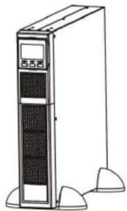
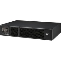
UPS 1500VA RACK MOUNT 2U
2-HE-USV MIT 1.500 VA ZUR RACKMONTAGE
ONDULEUR À MONTAGE SUR RACK 2U, 1500VA
UPS 1500VA RACK MOUNT 2U
UPS1RM2U1500
natural_image
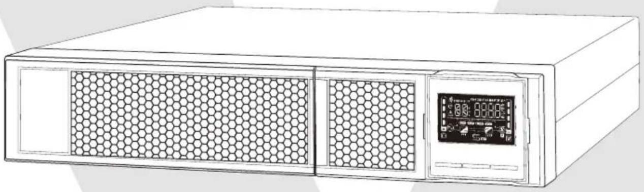
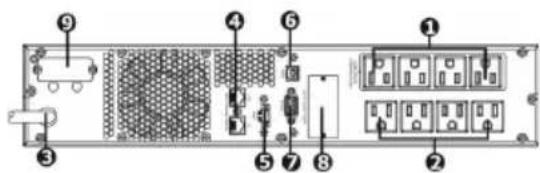
Line drawing of a server rack with hexagonal ventilation grilles and a digital display (no text or symbols)1.1 Rear Panel View
Note: Before installation, please inspect the unit. Be sure that nothing inside the package is damaged. Please keep the original package in a safe place for future use.
IEC Type NEMA Type
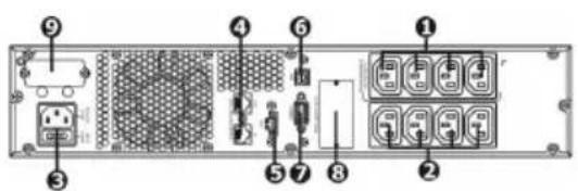
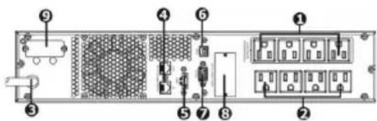
- Programmable outlets: connect to non-critiacal loads.
- Output receptacles: connect to mission-critical loads
- AC input
- Network/Fax/Modem surge protection
- Emergency power off function connector (EPO)
- USB communication port
- RS-232 communication port
- SNMP intelligent slot
- External battery connector
1.2 Operation
The UPS is composed of mains input, EMI/RFI Filters, Inverter, Battery charger, DC-to-DC converter, battery, AVR TX and UPS output
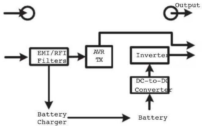
flowchart
graph TD
    A["Battery Charger"] --> B["EMI/RFI Filters"]
    B --> C["AVR TX"]
    C --> D["Inverter"]
    D --> E["Output"]
    F["Battery"] --> B
    G["DC-to-DC Converter"] --> D
1.3 Installation
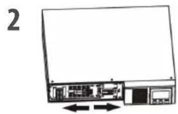
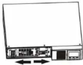
For safety consideration, the UPS is shipped out from factory without connecting battery wires. Before installation of the UPS, please follow the steps below to re-connect the battery wires.
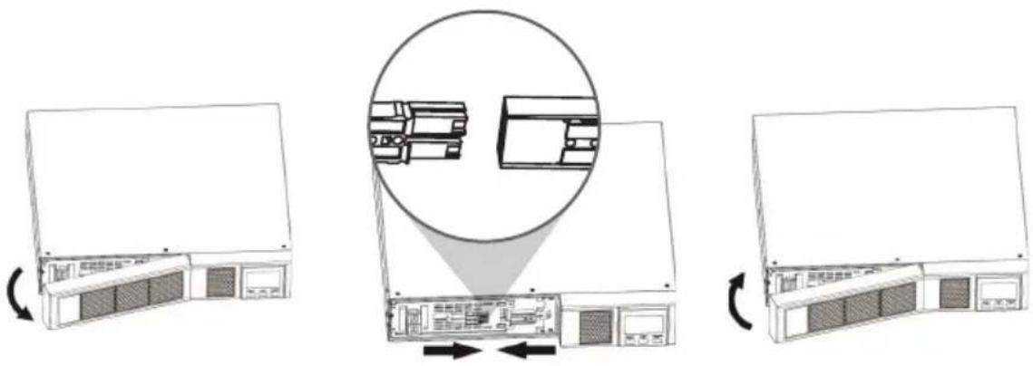
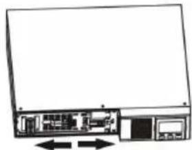
Remove Front Panel Connect the AC Input and re-connect battery wires
Put the front panel back on the unit
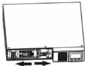
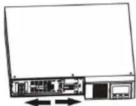
Rack-Mount Installation

Caution! – DO NOT use the mounting brackets to lift the unit. The mounting brackets are only for securing the unit to the rack.
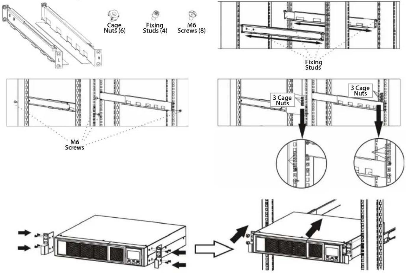
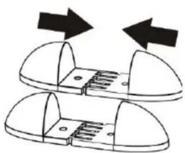
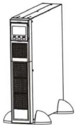
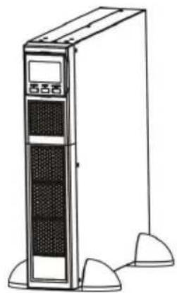
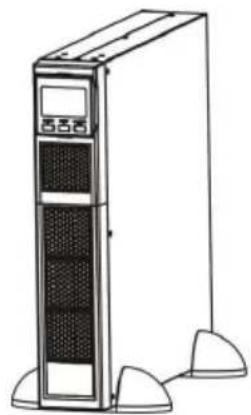
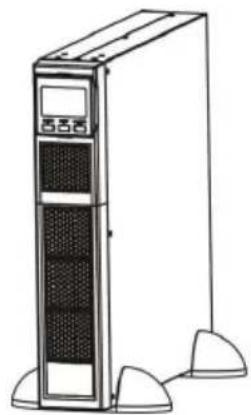
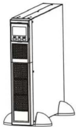
Tower Installation
123
natural_image
Diagram of two mechanical components with arrows indicating motion or force direction (no text or symbols)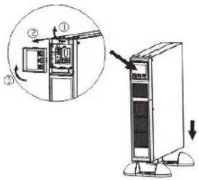
natural_image
Line drawing of a desktop tower with two side legs and front panel (no text or symbols)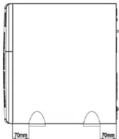
natural_image
Simple line drawing of a rectangular object with two side supports and two semicircular cutouts, labeled 70mm at the base (no text or symbols on the object itself)Note: When installing the UPS or battery pack with feet, please keep 70mm distance from the edge of the unit
1.4 Setup
1. UPS input connection
Plug the UPS into a grounded receptacle only. Avoid using extension cords, power strips or surge protectors
2. UPS output connection
There are two kinds of outputs: programmable outlets and general outlets. Please connect non-critical devices to the programmable outlets and critical devices to the general outlets. You may extend the backup time to critical devices by setting shorter backup time for non-critical devices
3. Communication connection (Optional)
USB Port

To allow for unattended UPS shutdown/start-up and status monitoring, connect the included USB cable from the computer to the UPS system
Note: USB port and RS-232 port can't work at the same time.
4. Network connection
Network/Fax/Phone surge port
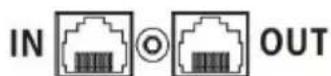
Connect a single modem/phone/fax/network line into surge-protected "IN" outlet on the back panel of the UPS unit. Connect from "OUT" outlet to the equipment with another modem/fax/phone/network line cable.
5. Disable and enable EPO function
This UPS is equipped with EPO function. Pin 1 and Pin2 are closed by default for normal UPS operation.
Note: The FPO function logic can be set up via LCD setting. Please refer to program 08 in UPS setting for the details
Method 1
Remove two top screws Pull out metal pin
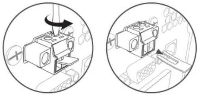
natural_image
Two circular diagrams showing a device with a rotating knob and a close-up of its internal components (no text or symbols)Method 2
Remove two front screws Pull out the entire green connector
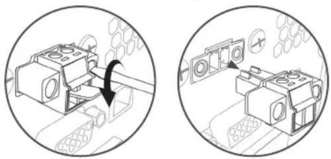
natural_image
Two technical diagrams showing mechanical assembly with arrows indicating rotation or movement (no text or symbols present)6. Turn on the UPS
Press the ON/Mute Button on the front panel for two seconds to power on the UPS.
Note: The battery charges fully during the first five hours of normal operation. Do not expect full battery run capability during this initial charge period
7. Install software (Optional for advanced users)
For optimal computer system protection, install UPS monitoring software to fully configure the UPS system. Please follow steps below to download and install monitoring software.
- Go to the website http://www.V7-world.com/downloads
- Select ViewPower software for your operating system to download the software.
- Follow the on-screen instructions to install the software.
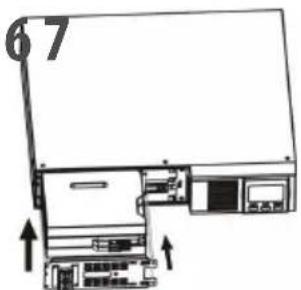
1.5 Battery Replacement
Note: This UPS is equipped with internal batteries and only a trained technician should replace the batteries.

Caution! – Adhere to all warnings, cautions, and notes before replacing batteries.
Note: When battery is disconnected, equipment is not protected from power outages.
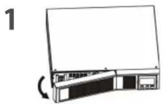
natural_image
Diagram of a computer monitor with an open screen and a curved scroll, no text or symbols presentRemove front panel Disconnect battery wires
natural_image
Diagram of a computer chassis showing internal components and memory, with no visible text or symbols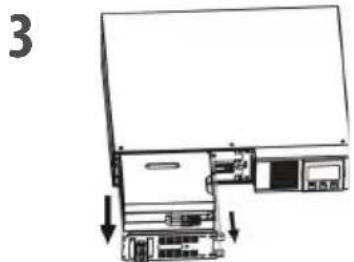
Pull out the battery box by removing two screws on the front panel
natural_image
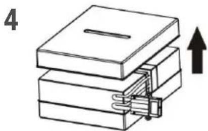
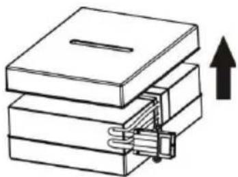
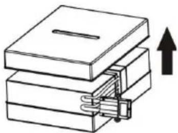
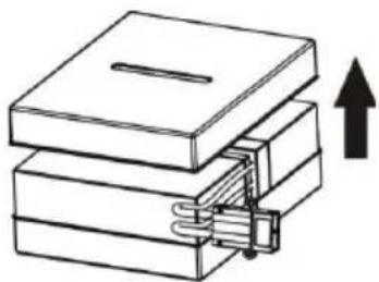
Stacked books with a handle and an upward arrow, no text or symbols presentRemove the top cover of battery box and replace the inside batteries
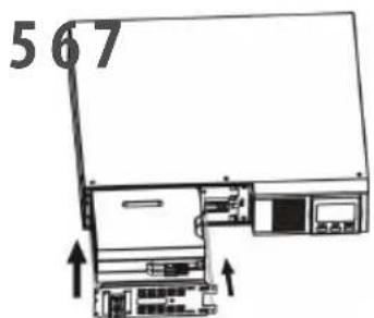
After replacing the batteries, put the battery box back to the its original location and screw it tightly
natural_image
Diagram of a computer monitor showing internal components and ventilation system (no text or labels)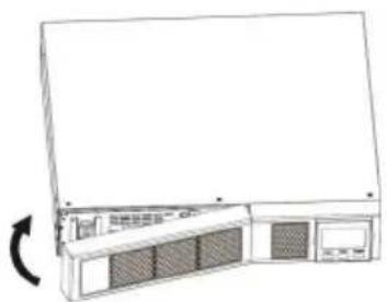
natural_image
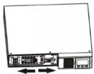
Line drawing of a server rack unit with a circular arrow indicating rotation (no text or symbols)Re-connect the battery wires Put the front panel back on the unit
2.1 Button Operations

flowchart
graph TD
    A["ON / MUTE"] --> B["SELECT"]
    B --> C["OFF / ENTER"]
Display Function
Backup Time Information


Indicates the estimated backup time. H = Hours M = Minutes S = Seconds
Configuration and Fault Information
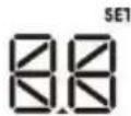
Indicates the configuration items, listed in detail in section 2.5
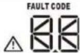
Indicates the warning and fault codes. Codes are listed in details in section 2.7 and 2.8
Mute Operation

Indicates the UPS alarm is disabled
Input, Battery, Temperature, Output & Load information
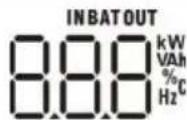
Indicates the input voltage, input frequency, battery voltage, battery capacity, ambient temperature, output voltage, output frequency, load current and load percentage K = Kilo W = Watt V = Voltage A = Ampere % = Percent °C = Degrees Centigrade Hz = Frequency
Load Information
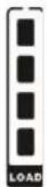
Indicates the load level by 0-24%, 25-49%, 50-74% and 75-100%

Indicates Overload
Programmable Outlets Information

Indicates that programmable management outlets are working
Mode Operation Information

Indicates the UPS connects to the mains

Indicates the battery is working

Indicates charging status
Indicates the ECO mode is enabling

Indicates the UPS is working in boost mode

Indicates the UPS is working in buck mode

Indicates the AC to DC circuit is working

Indicates the inverter circuit is working

Indicates the Output is working.
Battery Information
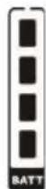
Indicates the battery level by 0-24%, 25-49%, 50-74%, and 75-100%

Indicates low battery
2.2 Audible Alarm
Battery Mode Sounds every 10 seconds
Low Battery Sounds every 2 seconds
Overload Sounds every second
Fault Continuously sounds
2.4 LCD Display Wording Index
| Abbreviation Display Content Definition | ||
| ENA / DIS | ENA / d1 S | Enable / Disable |
| ESC | ESC | Escape |
| ON | ON | ON |
| OK | OK | OK |
| EP | EP | EPO |
| AO / AC | AO / AC | Active Open / Active Close |
| TP | TP | Temperature |
| CH | CH | Charger |
| SF | SF | Site Fault |
| EE | EE | EEPROM Error |
| BR | BF | Battery Replacement |
| ST1 / ST2 / ST3 | ST1 / ST2 / ST3 | Input Waveform Sensitivity Setting |
2.5 UPS Setting
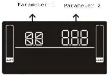
There are 2 parameters to set up the UPS
- For program alternatives (Refer to table below)
- Setting options or values for each program
Interface Setting
01 Output Voltage Setting
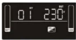
For EU Models you may choose 208/220/230/240 VAC settings 230VAC is the default. (Changing this setting is not recommended)
For US Models you may choose 110/115/120/127 VAC 120VAC is the default. (Changing this setting is not recommended)
02 Programmable outlets enable/disable
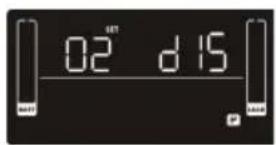
ENA > Programmable outlets enabled DIS > Programmable outlets disabled
03 Programmable outlet settings
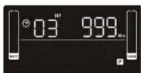
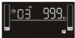
Set up the backup time limits in minutes from 0-999 for programmable outlets which connect to non-critical devices on battery mode. (Default = 999)
04 Maximum charger current setting
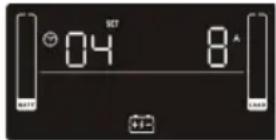
Set up the maximum charger current
You can change the charger setting to 1/2/4/6/8 ampere
(Default setting is 8A)
Note: this setting is only effective for super charger
06 Autonomy limitation setting
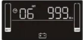
Set backup time on battery mode for general outlets.
Set the back up battery time from 0-999 minutes for general outlets on battery mode
DIS > Disable the autonomy limitation: back up time will depend on the battery capacity (Default setting)
Note: when setting is "0", the back up time will only be 10 seconds
07 Battery total AH setting
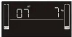
Set up the battery total AH of the UPS
Set the battery total capacity from 7-999 in AH
*Set the correct battery total capacity if there is a connected battery bank
08 EPO Logic Setting
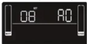
Set up the EPO function Control Logic
AO > Active Open (Default): When AO is selected as EPO Logic, it will activate EPO function with Pin 1 and Pin 2 in open status
AC > Active Close: When AC is selected as EPO logic, it will activate EPO function
with Pin1 and Pin 2 in closed status
09 Input waveform sensitivity setting
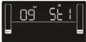
St1: high sensitivity. min 4/32 cycle detection and waveform distortion detection (Default)
St2: middle sensitivity. min 7/32 cycle detection
St3: low sensitivity. min 10/32 cycle detection (use with generators)
00 Exit setting
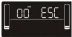
Exit the Setting mode
Step 1
Before entering setting mode, the UPS should be in Stand-by mode (off-charging) and make sure the battery is connected. The LCD display is shown on the right.
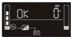
Step 2
Press and hold the "Select" button for 3 seconds to enter Setting Mode.
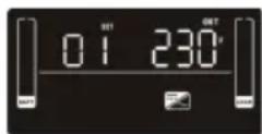
Step 3
Press the "Up" button (ON/MUTE) to switch to "02" of program list. Then press "Enter" button to enter value setting of parameter 2. Press the "Up" button to change the value to "ENA" to enable the programming outlet function. Then press "Enter" button again to confirm the setting.
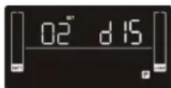
Step 4
Press the "Up" button (ON/MUTE) again to switch to "03" of program list. Then press "Enter" button for setting programmable outlet time. Push "Up" button to change the value of backup time. Then press "Enter" to confirm the setting.
Step 5
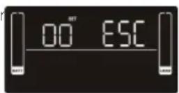
Press "Up" button (ON/MUTE) to switch to "00" of program list. Then press "Enter" button to exit setting menu.
Step 6
Disconnect AC input and wait until the LCD display is off. The new setting will be activated when turning on the UPS again.
2.6 Operating Mode Description
Operating Mode Description LCD Display
| ECO Mode When the input voltage is within voltage regulated range, UPS will power the output directly from the mains. ECO is an abbreviation of Efficiency Corrective Optimizer. In this mode, when the battery is fully charged, the fan will stop working to save energy | 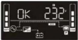 | |
| Buck Mode when AC is normal | When the input voltage is higher than the voltage regulation range but lower than high loss point, the buck AVR will be activated | 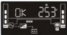 |
| Boost mode when AC is normal | When the input voltage is lower than the voltage regulation range but higher than low loss point, the boost AVR will be deactivated | 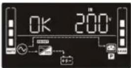 |
| Battery Mode When the input voltage is beyond the acceptable range or power failure and alarm is sounding every 10 seconds, UPS will backup power from battery | 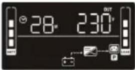 | |
| Standby Mode UPS is powered off and no output supply power, but can still charge batteries | 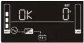 | |
| Fault Mode When a fault occurs, the ERROR icon and the fault code will be displayed | 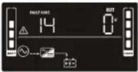 | |
2.7 Faults Reference Codes
Fault Event Fault Code Icon
| Bus start fail 01 x |
| Bus over 02 x |
| Bus Under 03 x |
| Inverter soft start fail 11 x |
| Inverter voltage high 12 x |
| Inverter voltage low 13 x |
| Fault Event Fault Code | Icon | |
| Inverter output short | 14 | x |
| Battery voltage too high 27 | x | |
| Battery voltage too low | 28 | x |
| Over temperature | 41 | x |
| Over load | 43 |  |
| Charger failure | 45 | x |
2.8 Warning Indicator
| Warning | Icon (Flashing) | Code | Alarm |
| Low battery |  |  | Sounds every 2 seconds |
| Overload |  |  | Sounds every second |
| Battery is not connected |  |  | Sounds every 2 seconds |
| Over Charge | 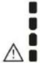 | 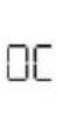 | Sounds every 2 seconds |
| Site wiring fault |  |  | Sounds every 2 seconds |
Warning Icon (Flashing Code Alarm
| EPO Enabled | [CBYW] | [CYS7] | Sounds every 2 seconds |
| Over temperature | [XHVT] |  | Sounds every 2 seconds |
| Charger Failure |  |  | Sounds every 2 seconds |
| Battery fault |  |  | Sounds every 2 seconds(UPS will turn off) |
| Battery replacement | [7SD5] | [SDAS] | Sounds every 2 seconds |
| EEPROM error |  | [Y4SC] | Sounds every 2 seconds |
Note: "Site Wiring Fault" function can be enabled/disabled via software. Please check software manual for the details.
If the UPS system does not operate correctly, please solve the problem by using the table below
Problems Cause Solution
| No indication and alarm even though the mains are normal | The AC input power is not connected | Check if input power cord firmly connected to the mains |
| The AC input is connected to the UPS output | Plug AC input power cord to AC input correctly | |
| The icon ⚠ and the warning codeEF flashing on LCD display and alarm is sounding every 2 seconds | EPO function is activated | Set the circuit in closed position to disable EPO function. |
| The icon ⚠ and the warning codeSF flashing on LCD display and alarm is sounding every 2 seconds | Line and neutral conductors of UPS input are reversed | Rotate main power socket by 180° and then connect to UPS system |
| The icon ⚠ and the warning codeNL flashing on LCD display and alarm is sounding every 2 seconds | The external or internal battery is incorrectly connected | Check if all batteries are connected |
| Fault code is shown as 27 on LCD display and alarm is continuously sounding | Battery voltage is too high or the charger is faulty | Contact your dealer |
| Fault code is shown as 28 on LCD display and alarm is continuously sounding | Battery voltage is too low or the charger is faulty | Contact your dealer |
| The icon ⚠ and the warning codeOL flashing on LCD display and alarm is sounding every second | UPS is overloaded | Remove excess loads from UPS output and restart |
| Fault code is show as 43 and the iconⓍ is lit on LCD display. Alarm sounds continuously | The UPS automatically shut down due to an overload at the output | Remove excess loads from the UPS output and restart |
| Fault code is shown as 14 and alarm sounds continuously | The UPS automatically shut down because of a short circuit on the UPS | Check output wiring and if connected devices are in short circuit status |
| Fault code is shown as 01, 02, 03, 11, 12, 13 and 41 on LCD display and alarm is continuously sounding | A UPS internal fault has occurred | Contact your dealer |
| Battery backup time is shorter than nominal value | Batteries are not fully charged | Charge the batteries for at least 5 hours and then check capacity. If the problem persists, consult your dealer |
| Batteries are defective | Contact your dealer to replace the batteries | |
| Fault code is show as 45 on LCD display and code is continuously sounding | The charger does not have output and battery voltage is less than 10V/PC | Contact your dealer |
3.1 Storage + Maintenance Operation
The UPS system contains no user-serviceable parts. If the battery service life of 3\~5 years at 25°C ambient temperature) has been exceeded, the batteries must be replaced. In this case, please contact your dealer

Pb:

Ph.
Be sure to deliver the spent battery to a recycling facility or ship it to your dealer in the replacement battery packing material
Storage
Storage Temperature Recharge Frequency Charging Duration
-25°C - 40°C Every 3 Months 1-2 hours
40°C - 45°C Every 2 Months 1-2 hours
4.1 Transportation
- Transport the UPS system only in the original package to protect against shock and impact
4.2 Preparation
- Condensation may occur if the UPS system is moved directly from a cold to warm environment. The UPS system must be absolutely dry before being installed. Please allow at least two hours for the UPS system to acclimate the environment.
- Do not install the UPS system near water or in moist environments.
- Do not install the UPS system where it would be exposed to direct sunlight or near a heater
- Do Not block ventilation holes in the UPS housing.
4.3 Installation
- Do not connect appliances or devices which can overload the UPS system (e.g. laser printers) to the UPS output sockets
- Place cables in such a way that no one can step on or trip over them.
- Do not connect appliances such as hair dryers to UPS output sockets.
- Connect the UPS system only to an earthed shock proof outlet.
- Please use only the included VDE-tested, CE-marked mains cable (e.g. the mains cable of your computer) to connect the UPS system to the building wiring outlet (shockproof outlet).
- Please use only VDE-tested, CE-marked power cables to connect the loads to the UPS system.
- When installing the equipment, ensure that the sum of the leakage current of the UPS and the connected devices does not exceed 3.5mA
- Temperature Rating - Units are considered acceptable for use in a maximum ambient temperature of 40^ (104°F)
- FOR PLUGGABLE EQUIPMENT, the socket-outlet shall be installed near the equipment and shall be easily accessible.
- CAUTION: The unit is heavy. Lifting the unit requires at least two people
- Check if there is a protection devices against over current and short circuit in the upstream of the UPS system. The recommended protection specification is 11A for 800VA\~1100VA, 15A for 1.5 VA, 20A for LV 2KVA and 30A for 2.5\~3KVA with a B or C trip curve.
4.4 Operation
- Do not disconnect the mains cable on the UPS system or the building wiring outlet (shockproof socket outlet) during operations since this would cancel the protective earthing of the UPS system and of all connected loads.
- The UPS system features its own, internal current source (batteries). The UPS output sockets or output terminals block may be electrically live even if the UPS system is not connected to the building wiring outlet.
- In order to fully disconnect the UPS system, first press the OFF/Enter button to disconnect the mains.
- Prevent fluids and other foreign objects from entering the UPS system.
- The EPO, RS-232 and USB circuits are IEC 60950-1 safety extra low voltage circuits by reinforced insulation
4.5 Maintenance, Service and Faults
• The UPS system operates with hazardous voltages. Repairs should be carried out only by a qualified technician
- CAUTION - risk of electric shock. Even after the unit is disconnected from the mains (building wiring outlet), components inside the UPS system are still connected to the battery and electrically live and dangerous.
- Before carrying out any kind of services and/or maintenance, disconnect the batteries and verify that no current is present and no hazardous voltage exists in the terminals of high capability capacitor such as BUS-capacitors.
• To avoid electrical shock, turn off the unit and unplug it from the AC power source before servicing the battery
- Only persons who are adequately familiar with batteries and with the required precautionary measures may replace batteries and supervise operations. Unauthorized persons must be kept well away from the batteries.
- CAUTION - risk of electric shock. The battery circuit is not isolated from the input voltage. Hazardous voltages may occur between the battery terminals and the ground. Before touching, please verify that no voltage is present.
- Batteries may cause electric shock and have a high short-circuit current. Please take the precautionary measures specified below and any other measures necessary when working with batteries:
- Remove wristwatches, rings and other metal objects
- Only tools with insulated grips and handles.
- When changing batteries, install the same number and same type of batteries.
- Do not attempt to dispose of batteries by burning them. This could cause battery explosion
- Do not open or destroy batteries. Escaping electrolyte can cause injury to the skin and eyes. It may be toxic
- When replacing batteries, use the same type and number of batteries or battery packs
- A battery can be at risk for electrical shock and high - short circuit current.
• The following precautions should be observed when working on batteries:
a. Remove watches, rings, or other metal objects.
b. Use tools with insulated handles.
c. Wear rubber gloves and boots.
d. Do not lay tools or metal parts on top of batteries.
e. Disconnect charging source prior to connecting or disconnecting battery terminals.
f. Determine if battery is inadvertently grounded. If inadvertently grounded, remove source from ground. Contact with any part of a grounded battery can result in electrical shock. The likelihood of such shock can be reduced if such grounds are removed during installation and maintenance
natural_image
Diagram of two mechanical components with arrows indicating motion direction (no text or symbols)
natural_image
Line drawing of a desktop tower with ventilation grilles and two side-mounted legs (no text or symbols)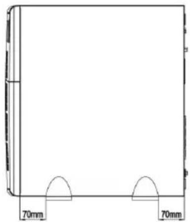
natural_image
Simple line drawing of a rectangular frame with two side supports and a 70mm measurement label (no text or symbols beyond measurement markers)natural_image
Two circular diagrams showing a device with a rotating knob and a close-up of its internal components (no text or symbols)Methode 2
natural_image
Two circular diagrams showing mechanical components with arrows indicating assembly or movement (no text or symbols present)natural_image
Diagram of a computer monitor with an open screen and a scroll, showing no text or symbols.2
natural_image
Diagram of a computer monitor showing internal components and an external screen (no text or symbols)natural_image
Diagram of a computer setup with monitor, tower, and drive unit (no text or labels)4
natural_image
Stacked books with a paperclip emerging from one end, showing an upward arrow (no text or symbols)natural_image
Diagram of a computer monitor showing internal components and ventilation slots (no text or labels)natural_image
Line drawing of a server rack unit with ventilation grilles and front panel (no text or symbols)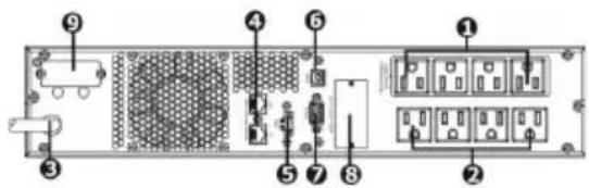
Installation en rack
natural_image
Diagram of two mechanical components with arrows indicating direction (no text or symbols)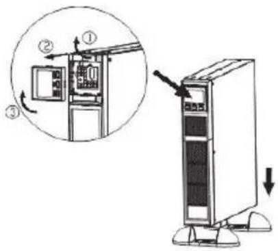
natural_image
Line drawing of a desktop tower with ventilation grilles and two side-mounted legs (no text or symbols)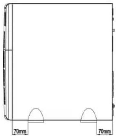
natural_image
Simple line drawing of a rectangular frame with two side supports and a 70mm measurement label (no text or symbols beyond measurement markers)natural_image
Two circular diagrams showing a device with a rotating knob and a close-up of its internal components (no text or symbols)Méthode 2
natural_image
Two technical diagrams showing mechanical assembly or assembly process, with no visible text or symbols.natural_image
Diagram of a device with a scroll and control panel, no text or symbols present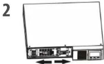
natural_image
Diagram of a computer monitor showing internal components and an external panel, with no visible text or symbols.natural_image
Stacked books with a handle and an upward arrow, no text or symbols presentnatural_image
Diagram of a computer monitor showing internal components and ventilation slots (no text or labels)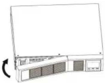
natural_image
Line drawing of a server rack unit with ventilation grilles and a scroll wheel (no text or symbols)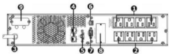
natural_image
Diagram of two mechanical components with arrows indicating direction, no text or symbols present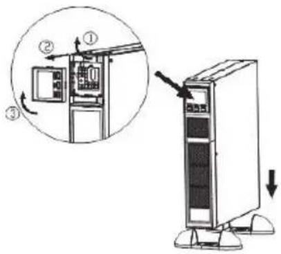
natural_image
Line drawing of a desktop tower with ventilation grilles and two side-mounted legs (no text or symbols)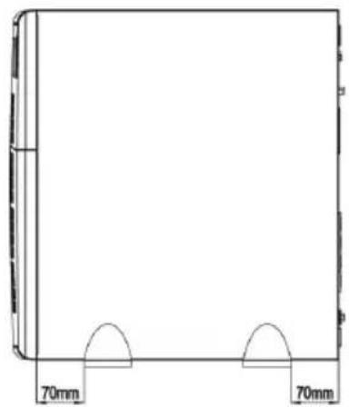
natural_image
Simple line drawing of a rectangular frame with two side supports and a 70mm measurement label (no text or symbols beyond measurement markers)natural_image
Two circular diagrams showing a device with a handle and a control panel, no text or symbols present.Método 2
natural_image
Two technical diagrams showing mechanical assembly or assembly process, with no visible text or symbols.natural_image
Simple line drawing of a computer monitor with an open screen and a scroll, no text or symbols present.2
natural_image
Diagram of a computer monitor showing internal components and an external screen (no text or symbols)natural_image
Diagram of a computer setup with monitor, tower, and rack (no text or labels)4
natural_image
Stacked books with a paperclip emerging from one end, showing an upward arrow (no text or symbols)natural_image
Diagram of a computer monitor showing internal components and ventilation slots (no text or labels)natural_image
Line drawing of a server rack unit with ventilation grilles and control panel (no text or symbols)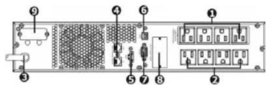
natural_image
Diagram of two mechanical components with arrows indicating direction (no text or symbols)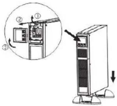
natural_image
Line drawing of a desktop tower with ventilation grilles and two side-mounted legs (no text or symbols)natural_image
Simple line drawing of a rectangular frame with two side supports and a 70mm measurement label (no text or symbols beyond measurement markers)1.4 Configurazione
natural_image
Two circular diagrams showing a device with a handle and a tool, no text or symbols present.Metodo 2
natural_image
Two circular diagrams showing mechanical components with arrows indicating a transformation or assembly (no text or symbols present)natural_image
Simple line drawing of a computer monitor with an open screen and a scroll, no text or symbols present.2
natural_image
Diagram of a computer monitor showing internal components and an external screen (no text or symbols)natural_image
Diagram of a computer setup with monitor, tower, and drive unit (no text or labels)natural_image
Stacked books with a paperclip and an upward arrow, no text or symbols presentRimuovere il coperchio superiore del vano batterie e sostituire le batterie interne
5
natural_image
Diagram of a computer monitor showing internal components and ventilation slots (no text or labels)natural_image
Line drawing of a server rack unit with ventilation grilles and a scroll wheel (no text or symbols)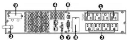
natural_image
Diagram of two mechanical components with arrows indicating motion or force direction (no text or symbols)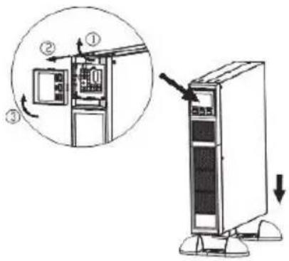
natural_image
Line drawing of a desktop tower with ventilation grilles and two side-mounted legs (no text or symbols)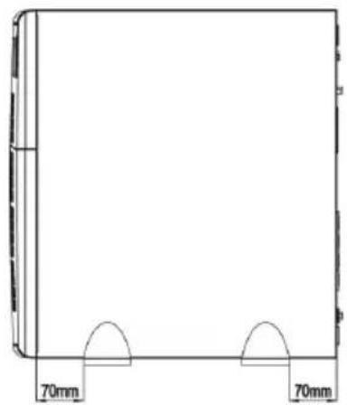
natural_image
Simple line drawing of a rectangular frame with two side supports and a 70mm measurement label (no text or symbols beyond measurement markers)natural_image
Two circular diagrams showing a device component with arrows indicating rotation and assembly (no text or symbols)Methode 2
natural_image
Two technical diagrams showing mechanical components in circular views, one with a curved arrow indicating rotation or assembly (no text or symbols)6. Schakel de UPS in
natural_image
Simple line drawing of a computer monitor with an open screen and a scroll, no text or symbols present.2
natural_image
Diagram of a computer monitor showing internal circuitry and memory compartment (no text or labels)natural_image
Diagram of a computer setup with monitor, tower, and drive unit (no text or labels)4
natural_image
Stacked books with a paperclip emerging from one end, showing an upward arrow (no text or symbols)natural_image
Diagram of a computer monitor showing internal components and an external panel (no text or symbols)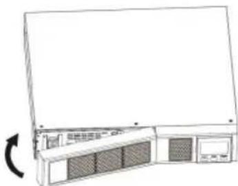
natural_image
Line drawing of a server rack unit with ventilation grilles and control panel (no text or symbols)H = uren M = minuten S = seconden
- UPS 1500VA RACK MOUNT 2U
- 2-HE-USV MIT 1.500 VA ZUR RACKMONTAGE
- ONDULEUR À MONTAGE SUR RACK 2U, 1500VA
- UPS1RM2U1500
- Rear Panel View
- IEC Type NEMA Type
- Operation
- Installation
- Rack-Mount Installation
- Tower Installation
- Setup
- UPS input connection
- UPS output connection
- Communication connection (Optional)
- Network connection
- Disable and enable EPO function
- Method 1
- Method 2
- Turn on the UPS
- Install software (Optional for advanced users)
- Battery Replacement
- Button Operations
- Display Function
- Mode Operation Information
- Battery Information
- Audible Alarm
- LCD Display Wording Index
- UPS Setting
- There are 2 parameters to set up the UPS
- Interface Setting
- Step 1
- Step 2
- Step 3
- Step 4
- Step 5
- Step 6
- Operating Mode Description
- Faults Reference Codes
- Warning Indicator
- Storage + Maintenance Operation
- Storage
- Transportation
- Preparation
- Installation
- Operation
- Maintenance, Service and Faults
- Methode 2
- Installation en rack
- Méthode 2
- Método 2
- Configurazione
- Metodo 2
- Schakel de UPS in
Brand : V7
Model : UPS1RM2U1500
Category : Uninterruptible power supply