BLMH 36 - Milling machine Black Line - Free user manual and instructions
Find the device manual for free BLMH 36 Black Line in PDF.


User questions about BLMH 36 Black Line
0 question about this device. Answer the ones you know or ask your own.
Ask a new question about this device
Download the instructions for your Milling machine in PDF format for free! Find your manual BLMH 36 - Black Line and take your electronic device back in hand. On this page are published all the documents necessary for the use of your device. BLMH 36 by Black Line.
USER MANUAL BLMH 36 Black Line
natural_image
Close-up of a black metal tool with a handle and labeled component '13' (no text or symbols on the tool itself)
text_image
4i 5 20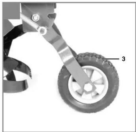
natural_image
Mechanical component with a tire and attached bracket, labeled with number 3 (no text or symbols on the object itself)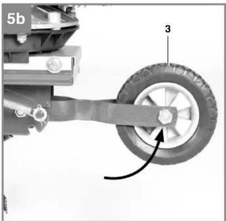
natural_image
Mechanical assembly diagram showing a wheel and suspension components (no text or symbols)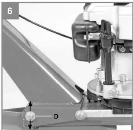
natural_image
Mechanical assembly diagram showing a component with labeled parts D and numbered marker 6 (no readable text or symbols beyond labels)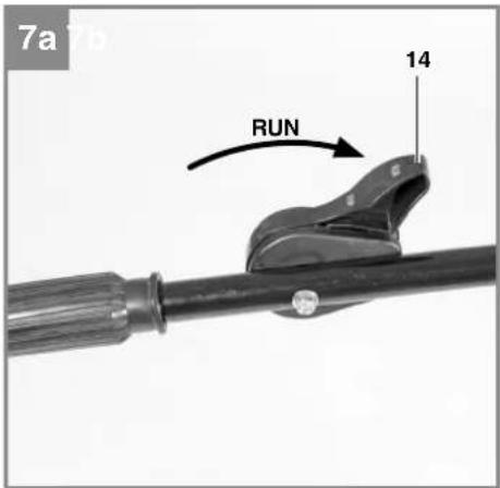
text_image
7a RUN 14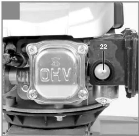
natural_image
Close-up of a mechanical device with a circular emblem and a dial, showing no readable text or symbols.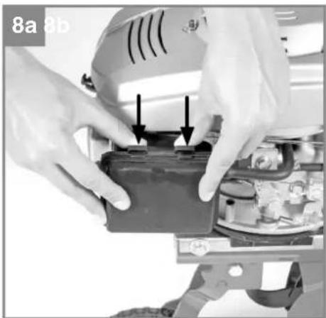
natural_image
Close-up of hands installing or adjusting a mechanical component with arrows indicating features (no visible text or symbols)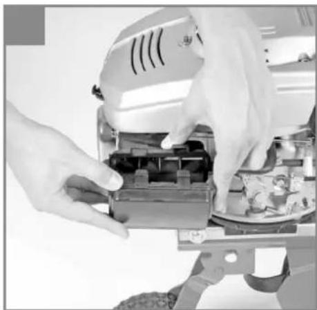
natural_image
Close-up of hands operating a robotic device with mechanical components (no visible text or symbols)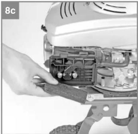
natural_image
Close-up of a robotic device with visible internal components and a hand adjusting its part (no text or symbols)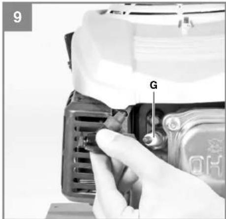
text_image
9 G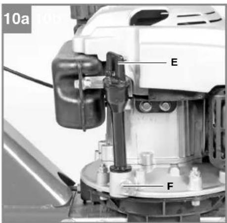
text_image
10a E F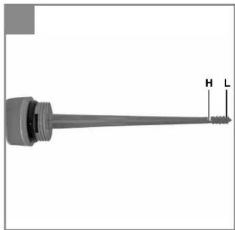
natural_image
Pure mechanical component diagram without any text, numbers, or symbols11
1

2

3


4

5
6
D
Gefahr!
Motor: 4-Takt, 99 cm
Bujiiile: Torch F7RTC
Nivelul presiunii sonore L_pA 79,2 dB (A)
When using the equipment, a few safety precautions must be observed to avoid injuries and damage. Please read the complete operating instructions and safety regulations with due care. Keep this manual in a safe place, so that the information is available at all times. If you give the equipment to any other person, hand over these operating instructions and safety regulations as well. We cannot accept any liability for damage or accidents which arise due to a failure to follow these instructions and the safety instructions.
1. Safety regulations
The corresponding safety information can be found in the enclosed booklet.
Danger!
Read all safety regulations and instructions. Any errors made in following the safety regulations and instructions may result in an electric shock, fire and/or serious injury.
Keep all safety regulations and instructions in a safe place for future use.
Explanation of the symbols on the machine (Fig. 11):
1 Important! Read the operating instructions. Follow the warnings and safety instructions.
2 Important! Risk of injury from rotating parts. Keep your hands, feet and clothing away from these parts.
3 Always make sure that the machine is standing solidly whenever you leave it.
4 Important! Hot machine parts. Keep your distance.
5 Important! Switch off the engine before refueling.
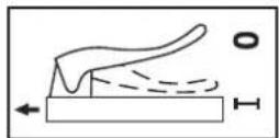
6 Description of the clutch lever: 0 = Hoe blade "Stop"; 1 = Hoe blade "On"
2. Layout and items supplied
2.1 Layout (Fig. 1-10)
- Engine / gear unit
- Reversing starter
- Transport wheel
- Depth stop
-
Steering handle holder
-
Safety split pin for depth stop
-
Steering handle – clutch lever
-
Steering handle - start/stop lever
-
5x screws size M8x30 for fastening the steering handle
-
4x nuts size M8
- 5x washers ∅8
- Clutch lever
- Safety lever
- Start/stop lever
- 1x screw size M6x45 for fastening the start/stop lever
- Cap nut size M6
- Cross strut
- 4x screws for fastening the cross strut
- Four nuts size M6
- Cable clip
- Spark plug wrench
- Fuel pump (primer)
2.2 Items supplied
Please check that the article is complete as specified in the scope of delivery. If parts are missing, please contact our service center or the sales outlet where you made your purchase at the latest within 5 working days after purchasing the product and upon presentation of a valid bill of purchase. Also, refer to the warranty table in the service information at the end of the operating instructions.
- Open the packaging and take out the equipment with care.
- Remove the packaging material and any packaging and/or transportation braces (if available).
- Check to see if all items are supplied.
- Inspect the equipment and accessories for transport damage.
- If possible, please keep the packaging until the end of the guarantee period.
Danger!
The equipment and packaging material are not toys. Do not let children play with plastic bags, foils or small parts. There is a danger of swallowing or suff oating!
• Original operating instructions
- Safetyinstructions
GB
3. Proper use
The machine is designed for digging over beds and fi elds. Be sure to observe the restrictions in the additional safety instructions.
The equipment is to be used only for its prescribed purpose. Any other use is deemed to be a case of misuse. The user / operator and not the manufacturer will be liable for any damage or injuries of any kind caused as a result of this.
Please note that our equipment has not been designed for use in commercial, trade or industrial applications. Our warranty will be voided if the machine is used in commercial, trade or industrial businesses or for equivalent purposes.
4. Technical data
Engine: 4-stroke engine, 99 ccm
Engine rating: 1.3 kW / 1.8 hp
Engine working speed: 3000 rpm
Working width: 36 cm
Starting system: ...... Reversing starter
Fuel: ...... Regular unleaded petrol
Engine oil: .... approx. 0.4 l (15W40)
Tank capacity: .... approx. 0.71
Vibration a_hv : 7 m/
K uncertainty 1.5 m/s
Weight: 27,2 kg
Spark plug: Torch F7RTC
L_pA sound pressure level ..... 79.2 dB(A)
K_pA uncertainty 3 dB
L_wA sound power level 93 dB(A)
5. Before starting the equipment
Assembly
- Insert the depth stop (4) into the opening at the back of the gear unit and fasten it with the safety split pin (5) at the working height you require (3 positions are available; when using for the first time we would recommend the middle position) (Fig. 4a).
- Plug the steering handle holder onto the engine unit. Insert the steering handle clutch lever (6) and the steering handle start/stop lever (7) through the openings in the steering handle holder (8) and fasten them with the screws (9), washers (11) and nuts (10) as shown in Fig.4b-4c.
- Fit the cross strut (17) as shown in Fig. 4d.
- Fit the engine start/stop lever (14) as shown in Fig. 4e.
-
Fitting and adjusting the clutch lever Fig. 4f -4g
-
Remove the clutch lever (12) from the steering handle (6). Undo the screw (A) and nut (B).
- Hook the actuator cable on the steering handle and adjust the actuator cable to maximum length by turning the lock nuts. This will make it easier to fit the clutch lever.
- Hook the actuator cable (C) on the clutch lever (Fig. 4f).
• Fit the clutch lever (12) to the steering handle (6). Do this with the screw (A) and nut (B).
• Important: Make sure that the safety lever (13) is positioned as shown in Fig. 4h. -
Adjust to the correct actuator cable length with the help of the adjuster (Fig. 4g/D) as follows: When the clutch lever is pressed there must be sufficient tension in the V-belt for the star-type hoes to turn, whereas when the clutch lever is released the star-type hoes must not move. Then tighten the two lock nuts against each other.
-
Fit the cable clip (20) as shown in Fig. 4i.
Caution! You must fill in engine oil and fuel before you start up for the first time.
- Check the fuel and engine oil levels and top up if required.
- Make sure that the ignition cable is secured to the spark plug.
- Check the area immediately around the power cultivator.
GB
6. Operation
- Set the depth stop (4) to the desired depth and secure with the split pin.
- Swing up the transport wheel and make sure that the bolt of the latch is engaged in the mount at the front (Fig. 5a-5b).
- You can adjust the steering handle to your physical size. To do so, undo the screws (Fig. 6/Item D), adjust the bracket and retighten the screws.
- To start the star-type hoes, pull up the safety lever (13) and press and hold down the clutch lever (12). Releasing the clutch lever will bring the star-type hoes to a stop (if they do not stop, readjust the clutch cable).
Starting the engine
- Ensure that the ignition cable is connected to the spark plug.
- Stand behind the power cultivator. Move the engine start/stop lever (Fig.7a/Item 14) into the RUN position.
- Press the fuel pump (primer) (Fig. 7b/Item 22) three times. You can skip this point if the engine has already warmed up.
- Start the engine using the reversing starter (Fig. 2/Item 2). To do this, pull out the handle approx. 10 – 15 cm (until you feel a resistance) and then start the engine with a sharp tug. If the engine does not start, tug the handle again.
Note! Never allow the actuator cable to snap back.
Note! In cold weather, it may be necessary to repeat the starting process several times.
Stopping the engine
Move the engine start/stop lever (Fig.7a/Item 14) into the STOP position.
7. Cleaning, maintenance, storage and ordering of spare parts
Danger!
Pull out the spark plug boot before doing any cleaning and maintenance work.
7.1 Cleaning
- Keep all safety devices, air vents and the motor housing free of dirt and dust as far as possible. Wipe the equipment with a clean cloth or blow it with compressed air at low pressure.
• We recommend that you clean the device immediately each time you have finished using it. - Clean the equipment regularly with a moist cloth and some soft soap. Do not use cleaning agents or solvents; these could attack the plastic parts of the equipment. Ensure that no water can seep into the device.
7.2 Maintenance
Please note: Switch off the unit immediately and contact an authorized dealer:
• In the event of unusual vibrations or noise.
- If the engine appears to be overloaded or misfires.
7.2.1 Air fi iter maintenance
- Check and clean the air filter before every use, and replace it if necessary.
- Remove the filter element (Fig. 8a-8c).
- Do not use abrasive cleaning agents or petrol to clean the element.
- Clean the element by tapping it on a flat surface.
• Assemble in reverse order.
7.2.2 Spark plug maintenance
Check the spark plug for dirt and grime after 10 hours of operation and if necessary clean it with a copper wire brush. Thereafter service the spark plug after every 50 hours of operation.
• Pull off the spark plug boot (Fig. 9) with a twist.
- Remove the spark plug (Fig. 9/Item G) with the supplied spark plug wrench.
• Assemble in reverse order.
GB
7.2.3 Changing the oil and checking the oil level (before using the machine)
The motor oil is best changed when the motor is at working temperature.
• Take out the dip stick (Fig. 10a / Item E).
- Open the drain screw (Fig. 10a / Item F) and allow the warm oil to drain into a drip tray.
- Close the drain screw again when all the waste oil has been drained.
- Fill up with engine oil as far as the top mark on the dip stick (Fig. 10b/H).
- Important: Do not screw the dip stick when you check the oil level, simply insert it as far as the thread (H = Max. / L = Min.).
- Dispose of the waste oil properly.
8. Disposal and recycling
The equipment is supplied in packaging to prevent it from being damaged in transit. The raw materials in this packaging can be reused or recycled. The equipment and its accessories are made of various types of material, such as metal and plastic. Never place defective equipment in your household refuse. The equipment should be taken to a suitable collection center for proper disposal. If you do not know the whereabouts of such a collection point, you should ask in your local council offices.
7.2.4 Adjusting the Bowden wires
In the working setting it should be possible to push the clutch lever up to the push bar without this requiring much effort. If the Bowden wire is too taut for this, it must be extended. To do this, undo the lock nut opposite the main cable, extend the screw connector and then tighten the lock nut again (see Fig. 4g/D). If the star-type hoes no longer rotate then the screw connector will have to be shortened again (as described above).
7.2.5 Power cultivator gearing
The gear unit is driven by a V-belt. The gear unit can be repaired if this should become necessary. If repairs are necessary, please contact our customer service center.
7.3 Storage
Empty the fuel tank before you decommission the unit for a lengthy period of time. Clean the unit and coat all the metal parts with a thin film of oil to prevent them rusting.
Store the unit in a clean, dry room.
7.4 Ordering replacement parts:
Please quote the following data when ordering replacement parts:
• Type of machine
• Article number of the machine
• Identification number of the machine
- Replacement part number of the part required For our latest prices and information please go to www.isc-gmbh.info
GB
9. Troubleshooting guide
Warning: Switch off the engine and pull out the ignition cable before making any checks or adjustments.
Warning: If, after making an adjustment or repair to the engine, you let it run for a few minutes, remember that the exhaust and other parts will get hot. Do not touch these parts as these may burn you.
| Fault Possible causes Remedy | ||
| The unit does not operate smoothly and vibrates intensively | - Bolts loose- Spark plug defective | - Check bolts- Replace spark plug |
| The engine does not start | - Spark plug defective- Fuel tank empty | - Replace spark plug- Top up fuel |
| Engine does not run smoothly | - Air fi Iter dirty- Spark plug soiled or defective | - Clean the air fi Iter- Clean or replace the spark plug |
| Drive power falls - Clutch play too large- V-belt loose | - Adjust clutch cable- Contact authorized customer service | |
| The engine will not start or dies after a short period of time | - Spark plug foul- No fuel | - Clean or replace spark plug- Top up fuel |
The reprinting or reproduction by any other means, in whole or in part, of documentation and papers accompanying products is permitted only with the express consent of the iSC GmbH.
Subject to technical changes
GB
Service information
We have competent service partners in all countries named on the guarantee certificate whose contact details can also be found on the guarantee certificate. These partners will help you with all service requests such as repairs, spare and wearing part orders or the purchase of consumables.
Please note that the following parts of this product are subject to normal or natural wear and that the following parts are therefore also required for use as consumables.
| Category Example | |
| Wear parts* | Spark plug, air filter, cultivator blade, V-belt, coupling, fuel fi iter |
| Consumables* | |
| Missing parts |
* Not necessarily included in the scope of delivery!
In the effect of defects or faults, please register the problem on the internet at www.isc-gmbh.info. Please ensure that you provide a precise description of the problem and answer the following questions in all cases:
• Did the equipment work at all or was it defective from the beginning?
• Did you notice anything (symptom or defect) prior to the failure?
• What malfunction does the equipment have in your opinion (main symptom)?
Describe this malfunction.
GB
Warranty certifi cate
Dear Customer,
All of our products undergo strict quality checks to ensure that they reach you in perfect condition. In the unlikely event that your device develops a fault, please contact our service department at the address shown on this guarantee card or the sales outlet from where you bought the device. Please note the following terms under which guarantee claims can be made:
- These guarantee conditions regulate additional guarantee services. Your statutory guarantee claims are not affected by this guarantee. Our guarantee is free of charge to you.
-
Our guarantee only covers defects suffered by the device which have been verifiably caused by a material or manufacturing fault and is limited to the rectification of such defects or the replacement of the device at our discretion.
Please note that our devices are not designed for use in commercial, trade or professional applications. A guarantee contract will not be created if the device has been used by commercial, trade or industrial business or has been exposed to similar stresses during the guarantee period. -
The following are not covered by our guarantee:
- Damage to the device caused by a failure to follow the assembly instructions or due to incorrect installation, a failure to follow the operating instructions (for example connecting it to an incorrect mains voltage or current type) or a failure to follow the maintenance and safety instructions or by exposing the device to abnormal environmental conditions or by lack of care and maintenance.
- Damage to the device caused by abuse or incorrect use (for example overloading the device or the use or unapproved tools or accessories), ingress of foreign bodies into the device (such as sand, stones or dust, transport damage), the use of force or damage caused by external forces (for example by dropping it).
- Damage to the device or parts of the device caused by normal or natural wear or tear or by normal use of the device.
- Damage to the device caused by a failure to follow the assembly instructions or due to incorrect installation, a failure to follow the operating instructions (for example connecting it to an incorrect mains voltage or current type) or a failure to follow the maintenance and safety instructions or by exposing the device to abnormal environmental conditions or by lack of care and maintenance. - Damage to the device caused by abuse or incorrect use (for example overloading the device or the use or unapproved tools or accessories), ingress of foreign bodies into the device (such as sand, stones or dust, transport damage), the use of force or damage caused by external forces (for example by dropping it). - Damage to the device or parts of the device caused by normal or natural wear or tear or by normal use of the device.
- The guarantee is valid for a period of 2 years starting from the purchase date of the device. Guarantee claims should be submitted before the end of the guarantee period within two weeks of the defect being noticed. No guarantee claims will be accepted after the end of the guarantee period. The original guarantee period remains applicable to the device even if repairs are carried out or parts are replaced. In such cases, the work performed or parts fitted will not result in an extension of the guarantee period, and no new guarantee will become active for the work performed or parts fitted. This also applies if an on-site service is used.
Also refer to the restrictions of this warranty concerning wear parts, consumables and missing parts as set out in the service information in these operating instructions.
Hornbach Baumarkt AG, Hornbachstraße 11, 76879 Bornheim / Germany
www.hornbach.com
X 2000/14/EC\_2005/88/EC
□ Annex V
X Annex VI
Noise: measured L_max = 91.4 dB (A); guaranteed L_min = 93 dB (A)
P = 1,3 KW; L/∅ = cm
Notified Body: TÜV SÜD Industrie Service GmbH, Westendstraße 199,
80686 München, Deutschland, (0036)
X 2004/26/EC
Emission No.: e11*97/68SA^2010/26^2845*00
Standard references: EN 709; EN ISO 14982
Subject to change without notice
Archive-File/Record: NAPR011053
Documents registrar: Markus Jehl
Wiesenweg 22, D-94405 Landau/Isar
EH 11/2014 (01)