
Z10150 - Subwoofer PHOENIX GOLD - Free user manual and instructions
Find the device manual for free Z10150 PHOENIX GOLD in PDF.

| Product Type | Flat Active Subwoofer |
| Brand | Phoenix Gold |
| Model | Z10150 |
| Dimensions (L x W x H) | 354 x 250 x 68 mm |
| RMS Power | 150 W |
| Total Harmonic Distortion | < 0.4% @ 100 Hz |
| Signal-to-Noise Ratio | > 90 dB |
| Frequency Response | 20 Hz - 150 Hz |
| High-Level Input Sensitivity | 0.5 V |
| Low-Level Input Sensitivity | 110 mV |
| Low-Pass Filter | 50 Hz - 150 Hz |
| Bass Boost | 0 - 18 dB at 45 Hz |
| Subsonic Filter | 20 Hz - 50 Hz |
| Adjustable Phase | 0 - 180° |
| Fuse Rating | 20 A |
| Speaker | 10\" (25 cm) |
| Power Supply | MOSFET PWM |
| Protection | Thermal, overload, short circuit |
| Auto Power On | Yes (on/off) |
| Level Remote Control | Yes (included) |
| Inputs | RCA high and low level |
| Soft Start | Yes |
Frequently Asked Questions - Z10150 PHOENIX GOLD
User questions about Z10150 PHOENIX GOLD
0 question about this device. Answer the ones you know or ask your own.
Ask a new question about this device
Download the instructions for your Subwoofer in PDF format for free! Find your manual Z10150 - PHOENIX GOLD and take your electronic device back in hand. On this page are published all the documents necessary for the use of your device. Z10150 by PHOENIX GOLD.
USER MANUAL Z10150 PHOENIX GOLD
8” & 10” Slim Active Bass Enclosures
Model: Z8150V2 - Z10150
FEATURES
MOSFET PWM (Pulse Width Modulated) Power Supply
Soft turn-on circuit
Variable input gain control
Variable bass boost (0 to 18dB)
RCA low level and high level inputs
LED power and protection indicators
Thermal, overload and speaker short protection
Remote turn-on/turn-off circuit
Variable low and subsonic crossovers
Variable phase (0 to 180 degree)
Auto Power On: ON/OFF
Remote subwoofer level control
INTRODUCTION
Slim enough to fit underseat or any other hide away location both 8'' & 10'' Slim Active Bass Enclosures offer a quick and easy way to add a high-powered subwoofer solution to your audio system.
The integrated amplifier in the subwoofer features both subsonic and low pass crossovers, and a control for adjusting the input sensitivity from 0.2V to 6V.
Both high level (speaker level) and low level (RCA type) inputs are present, making this a universal solution for use with any head unit or other input source.
For further flexibility, a variable bass boost control has been included allowing you to control the subwoofer from the front seat.
WHAT'S IN THE BOX
When first unpacking your new amplified subwoofer, please check that the package contains all of the items right. If something is missing, contact the store where you purchased the product.
Amplified subwoofer
Remote subwoofer level control
Remote subwoofer control cable
High level input harness/wire
Mounting hardware
KEY FEATURES
MOSFET PWM (Pulse Width Modulated) Power Supply
Thermal, overload and speaker short protection
Soft turn-on circuit
Remote turn-on/turn-off circuit
Variable input gain control
Variable low and subsonic crossovers
Variable bass boost (0 to 18dB)
Variable phase (0 to 180 degree)
RCA low level & high level inputs
Auto Power On: ON/OFF
LED power & protection indicators
Remote subwoofer level control
GENERAL PRECAUTIONS
Before installing and using your new amplified subwoofer, please become familiar with all the information contained in this manual. Please keep this manual in a safe place for future reference.
- Do not open or attempt to repair this unit yourself. Dangerous high voltages are present which may result in electric shock. Refer any repairs to a qualified service technician.
- To avoid risk of electric shock or damage to the unit, do not permit any of this equipment to become damp or wet. If this does occur, immediately unplug the power wires and send the product to your local dealer or service centre as soon as possible.
- If there is smoke or any peculiar odour present during use or if there is damage to any of the enclosures components, immediately unplug the power cord and send the product to your local dealer or service centre as soon as possible.
SHOCK HAZARD
Do not open the case of this product. There are dangerous voltages present within the unit. There are no user-serviceable parts within the unit.
PROTECTION CIRCUITRY
The built-in amplifier incorporates special protection circuitry which will disable the amplifier if any of the following should occur:
Input overload
Short circuit
Extremely high temperatures
If any of these conditions are detected, the amplifier will go into a self-protection mode, and the PROTECT LED on the control panel will glow RED in colour.
What should I do if the POWER STATUS LED turns RED?
If you observe that the POWER STATUS LED is RED, please check the system carefully to determine what has caused the protection circuit to engage.
To reset the amplified subwoofer when it is in PROTECT mode, turn the power off to the system (usually by turning off the head unit or other signal source which feeds the amplifier) and then turn it on again.
If the internal amplifier has shut down due to thermal overload, you should first allow it to cool down before restarting.
If the shut down was due to either an input overload or a short circuit, be sure to correct these conditions before attempting to power up the subwoofer again.
MOUNTING THE SUBWOOFER
-
Find a suitable location in the vehicle in which to mount the amplifier. A typical location is shown opposite.
-
Make sure there is sufficient air circulation around the intended mounting location.
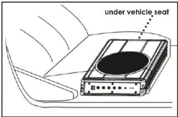
- Mark the location for the mounting hole screws by positioning the cabinet where you wish to install it. Make a small mark to identify the position and remove the unit.
Thoroughly clean the area you plan to attach the subwoofer, using a vacuum cleaner.
CONNECTING THE SUBWOOFER
Before connecting any wiring look through this manual and identify the diagrams to follow for power, input and speaker connections for your particular installation. Be sure you understand all the connections before you proceed.
- Connect the ground terminal to the closest point on the chassis of the vehicle. Keep this ground wire to less than 39" (100cm) in length. Use 8 gauge (or heavier) wire.
- Connect the remote terminal to the remote output of the head unit using 16 gauge (or heavier) wire.
- Connect an empty fuse holder within 18" (45cm) of the car battery, and run 8 gauge (or heavier) cable from this fuse to the amplifier location.
- Check that the fuse holder doesn't contain a fuse. Next, connect the fuse holder to the "BATT+" connection on the amplifier.
- Connect all line inputs using high-quality cables.
- Insert fuse(s) into battery fuse holders.
- Recheck all connections before powering up the subwoofer.
- Set all level controls to minimum position, and set all crossover control/switches to the desired frequency points.
- Power up the head unit and the subwoofer. Then set the volume control on the head unit to about 75% volume, and adjust the subwoofer's input level controls to just below the level of distortion.
- Further fine tuning of the various controls may be necessary to obtain best results.
Don't misuse the level control!
Do not mistake the input level control for a volume control! It is designed ONLY to match the output level of your audio source to the input level of your subwoofer.
Do not adjust this input level to maximum unless your input level requires it. Ignoring these instructions will result in an input overload to the amplifier in the subwoofer, and excessive audio distortion. It can also cause the protection circuit to engage.
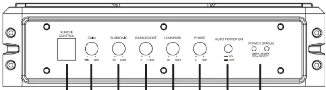
Front Panel controls & features
12345678
-
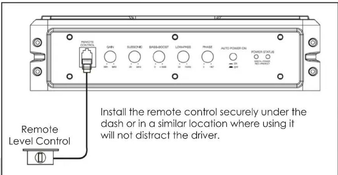
REMOTE LEVEL CONTROL PORT - Attach the included remote level control to adjust the volume level of the subwoofer independently.
-
INPUT GAIN CONTROL - After you have installed your system, turn this control to minimum. Turn the head unit on (and the subwoofer will turn on via the remote connection). Turn the head unit volume to about 75% full level. Slowly turn up the subwoofer input gain control until you hear a small amount of distortion. Then reduce the level until the distortion is completely gone. Leave the control at this setting.
-
SUBSONIC FILTER - Use this control to filter out low frequency noise and rumble.
-
BASS BOOST - The bass boost feature will increase the sound level in the bass frequencies.
-
LOW PASS FILTER - This control permits you to define the frequency range you want the subwoofer amplifier to receive. The subwoofer will reproduce all sound BELOW the frequency you set. If the rest of your system is weak on the mids, you may wish to set this control relatively high. If the midrange is well covered by the rest of your system, you will probably want the subwoofer to only receive lower frequency signal.
-
PHASE - Use this control to help compensate for time alignment problems in the system. Such problems usually result from having the subwoofer at a different distance from the listener than the other speakers in the system.
7. AUTO POWER ON
The AUTO POWER ON (ON / OFF) is for high level (speaker-level) connections. When the switch is in the "ON" position, the subwoofer AUTO POWER ON when there is signal input. If the amplifier detected no signal input, the amplifier will auto turn off. If you prefer to use the remote turn on/off connection, the switch is in the OFF position.
8. POWER STATUS LED
The green LED lights up when the unit is powered on and functioning correctly. Should a problem be detected then the red light will illuminate.
Rear Panel controls & features
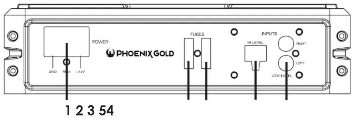
1. POWER TERMINALS
- FUSE - The fuse in the left socket is the fuse which provides protection for the circuitry. Do not use a fuse with a different value and NEVER replace the fuse with a wire or coin.
- SPARE FUSE - The right fuse socket is a storage location for a spare fuse. If the left fuse blows, you may replace it with this fuse. Please ensure it is the correct fuse amperage.
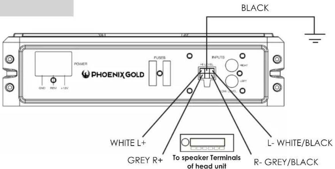
4. HIGH LEVEL (speaker level) INPUTS
If your head unit does not have RCA outputs, you can use the speaker outputs for the audio source for the subwoofer. Use the supplied cable and wire harness and connect the outputs properly as shown in the connection diagram in this manual.
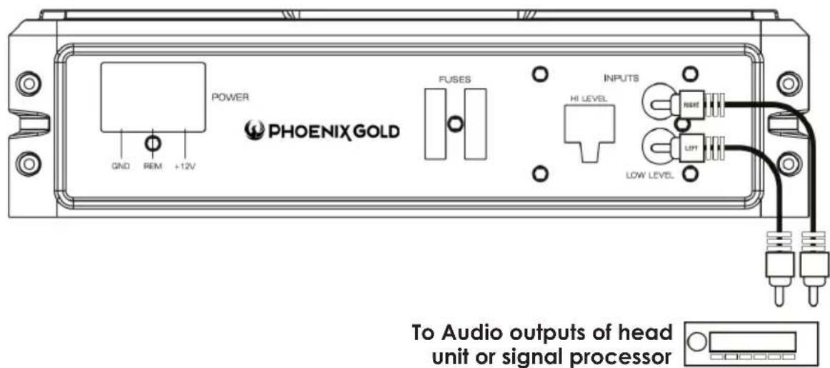
5. LOW LEVEL RCA INPUTS
Low level inputs are the recommended way to introduce the audio signal to the subwoofer if RCA outputs are present on your head unit or other signal source (such as a sound processor).
Low Level Input Wiring
Low-level (RCA) input wiring is preferred for best audio performance. Most boot or hatchback installations will require a 5m RCA cable, while pickup trucks and under-seat installations will require a 3m RCA cable. Always use a high quality cable.
NOTE: Do not connect BOTH the high level and low level inputs from your receiver to your amplifier at the same time!
High Level Input Wiring
The high level input(s) should only be used when your receiver lacks RCA outputs. If the RCA outputs are not present, connect the speaker outputs from the receiver to the high level input connector of the amplifier. Be sure to observe polarity to avoid audio phase problems.
NOTE: Do not connect BOTH the high level and low level inputs from your receiver to your amplifier at the same time!
Power Connections
Connect the ground terminal to the closest point on the chassis of the vehicle. Keep this ground wire to less than 39" (100 cm) in length. Use 8 gauge (or heavier) wire.
Connect the remote terminal to the remote output of head unit using 16 gauge (or heavier) wire.
Connect an empty fuse holder within 18" (45 cm) of the car battery, and run 8 gauge (or heavier) cable from this fuse to the amplifier location. Then connect the fuse holder to the "BATT+" (+12V) connection on the subwoofer rear panel.
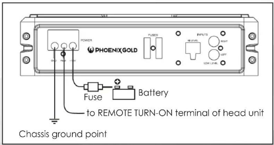
Power Connections
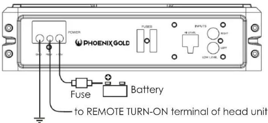
Chassis ground point
If you are using the High Level Inputs and wish to use the auto turn on feature you must set the auto turn on switch to ON. The subwoofer will then turn on when a signal is detected. If there is no signal detected then the subwoofer will switch off.
Remote Level Control Connection
Specifications
| Z8150V2 Z10150 | ||
| RMS power 150W RMS 150W | RMS | |
| THD <0.4% @ 100Hz <0.4% @ 100Hz | ||
| Signal-to-noise ratio >90dB >90dB | ||
| Frequency response 20Hz-150Hz 20Hz-150Hz | ||
| Input Sensitivity, High Level 0.5V 0.5V | ||
| Input Sensitivity, High Level 1.0mV 110mV | ||
| Low Pass Filter 50Hz-150Hz 50Hz-150Hz | ||
| Bass Boost 0-18dB @ 45Hz 0-13dB @ 45Hz | ||
| Subsonic Filter 20Hz-50Hz 20Hz-50Hz | ||
| Variable Phase | 0-180° | 0-180° |
| Fuse Rating | 20A 20A | |
| Subwoofer | 8" - 2Ohm 10" - 2Ohm | |
| Dimensions (L x W H) mm | 354 x 250 x 68 | 354 x 250 x 68 |
Troubleshooting
| SYMPTOM | POSSIBLE REMEDY |
| Amplifier will not power up | Check to make sure you have a good ground connection. Check that the Remote Input (Turn-On) has at least 5VDC. Check that there is battery power on the (+) terminal. Check that there is at least 12V. Check all fuse, replace if necessary. Make sure that the Protection LED is not illuminated. If it is glowing red, shut off the amplifier briefly, and then repower it. |
| Protection LED comes on when amplifier is powered up | Check the amplifier is not too hot. |
| No output | Check that the fuses are OK. Check that the unit is properly grounded. Check that the remote Input (Turn-On) has at least 5V DC Check that the RCA audio cables are plugged into the proper inputs. |
| Low Output | Reset the Level Control. Check the Crossover Control settings. |
| Distorted sound | Check that the Input Level Control is set to match the signal level of the head unit. Always try to set the Input Level as low as possible. Check that all crossover frequencies are properly set. Check for short circuits on the speaker leads. |
| Amplifier gets very hot | Check that there is good air circulation around the amp. In some applications, it may be necessary to add and external cooling fan. |
| Engine noise (static type) | This is usually caused by poor quality RCA cables, which can pick up radiated noise. Use only the best quality cables, and route them away from power cables. |
| Engine Noise (alternator whine) | Check that the RCA grounds are not shorted to the vehicle chassis Check that the head unit is properly grounded. |

Designed and Engineered in the USA
Made in China