
VC-WL 60/200 - Battery charger VOLTCRAFT - Free user manual and instructions
Find the device manual for free VC-WL 60/200 VOLTCRAFT in PDF.

| Product type | Battery charger and engine starter |
| Brand | Voltcraft |
| Model | VC-WL 60/200 |
| Power supply | 220-240 V AC, 50-60 Hz, 13 A max |
| 12 V output | 10 A, 30 A, 60 A |
| 24 V output | 5 A, 15 A, 30 A |
| Emergency start | 12 V DC, 200 A (cycle 5 s ON / 180 s OFF) |
| Max charging voltage (12 V) | STD 14.4 V, AGM 14.7 V, GEL 14.1 V |
| Max charging voltage (24 V) | STD 28.8 V, AGM 29.4 V, GEL 28.2 V |
| Recommended battery capacities | 10 - 600 Ah |
| Compatible battery types | Lead-acid: STD (WET, MF), AGM, GEL |
| Protection | Overload, overheating, reverse polarity, short circuit, excessive current |
| Fuses | 2 × 80 A |
| Dimensions (L × H × D) | 279 × 800 × 390 mm |
| Weight | 16 kg |
| Cable length | 1.9 m |
| Protection rating | IP20 |
| Operating conditions | +20 to +40 °C, 10-85 % RH (non-condensing) |
| Storage conditions | -30 to +70 °C, 10-95 % RH (non-condensing) |
| Package contents | Charger, handle, stand, wheels, spare fuses, manual |
| Cleaning | Dry, lint-free cloth. Do not immerse. |
| Repairability | Fuses replaceable by user. Other repairs by a professional. |
Frequently Asked Questions - VC-WL 60/200 VOLTCRAFT
User questions about VC-WL 60/200 VOLTCRAFT
0 question about this device. Answer the ones you know or ask your own.
Ask a new question about this device
Download the instructions for your Battery charger in PDF format for free! Find your manual VC-WL 60/200 - VOLTCRAFT and take your electronic device back in hand. On this page are published all the documents necessary for the use of your device. VC-WL 60/200 by VOLTCRAFT.
USER MANUAL VC-WL 60/200 VOLTCRAFT
natural_image
Technical line drawing of a wheeled robotic vehicle with visible wheels and mounting brackets (no text or symbols)7 Erste Schritte
11 Fehlersuche
Copyright by Conrad Electronic SE.
*2472503_V2_0123_dh_mh_de 9007199882313355-1 I2/O2 en
VOLTCRAFT
GB Operating Instructions
VC-WL 60/200
Battery Charger / Engine Starter
Item no: 2472503
CE

1 Intended use
The product is a battery charger and engine starter that is compatible with various battery types (e.g., STD, GEL, AGM).
The product is intended for indoor use only. Do not use it outdoors.
Contact with moisture must be avoided under all circumstances.
If you use the product for purposes other than those described, the product may be damaged.
Improper use can result in short circuits, fires, electric shocks or other hazards.
The product complies with the statutory national and European requirements
For safety and approval purposes, you must not rebuild and/or modify the product.
Read the operating instructions carefully and store them in a safe place. Make this product available to third parties only together with the operating instructions.
All company names and product names are trademarks of their respective owners. All rights reserved.
2 Delivery contents
Product
1x trolley handle
4x handle screws
1x trolley stand
4x stand screws
1x wheel axle
2x wheel bearing hub washer
2x c-clips (for axle)
2x wheels
2x wheel hub caps
2x 80A (bolt on OTO strip) fuses
Operating instructions
3 Latest product information
Download the latest product information at www.conrad.com/downloads or scan the QR code shown. Follow the instructions on the website.
4 Description of symbols
The following symbols are on the product/appliance or are used in the text:

The symbol warns of hazards that can lead to personal injury.

The symbol warns of dangerous voltage that can lead to personal injury by electric shock.

This product must only be used in dry, enclosed indoor areas. It must not become damp or wet, as this may cause a fatal electric shock!

For safe and proper use, follow these instructions. Keep them for future reference.

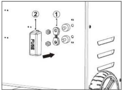
Fuse location
5 Safety instructions

Read the operating instructions carefully and especially observe the safety information. If you do not follow the safety instructions and information on proper handling, we assume no liability for any resulting personal injury or damage to property. Such cases will invalidate the warranty/guarantee.
5.1 Read first!
This appliance can be used by children aged from 8 years and above and persons with reduced physical, sensory or mental capabilities or lack of experience and knowledge if they have been given supervision or instruction concerning use of the appliance in a safe way and understand the hazards involved.
■ Children shall not play with the appliance.
- Cleaning and user maintenance shall not be made by children without supervision.
■ WARNING Never recharge non-rechargeable batteries.
5.2 General
The product is not a toy. Keep it out of the reach of children and pets.
Do not leave packaging material lying around carelessly. This may become dangerous playing material for children.
If you have questions which remain unanswered by this information product, contact our technical support service or other technical personnel.
Maintenance, modifications and repairs must only be completed by a technician or an authorised repair centre.
5.3 Handling
- Handle the product carefully. Jolts, impacts or a fall even from a low height can damage the product.
5.4 Operating environment
- Do not place the product under any mechanical stress.
■ Protect the appliance from extreme temperatures, strong jolts, flammable gases, steam and solvents.
■ Protect the product from high humidity and moisture. - Protect the product from direct sunlight.
Do not switch the product on after it has been taken from a cold to a warm environment. The condensation that forms might destroy the product. Allow the product to reach room temperature before you use it.
5.5 Operation
Consult an expert when in doubt about the operation, safety or connection of the product.
If it is no longer possible to operate the product safely, take it out of operation and protect it from any accidental use. DO NOT attempt to repair the product yourself. Safe operation can no longer be guaranteed if the product:
- is visibly damaged.
– is no longer working properly,
– has been stored for extended periods in poor ambient conditions or
– has been subjected to any serious transport-related stresses.
5.6 Mains cable

Do not modify or repair mains supply components including mains plugs, mains cables, and power supplies. Do not use damaged components. Risk of death by electric shock!
The mains outlet must be located near to the device and be easily accessible.
■ Never plug in or unplug the mains plug when your hands are wet.
- Never pull the mains plug from the socket by pulling at the cable. Always pull it from the mains socket using the intended grips.
- Unplug the mains plug from the mains socket if you do not use the device for an extended period of time.
■ Disconnect the mains plug from the mains socket in thunderstorms for reasons of safety.
Make sure that the mains cable is not squeezed, bent, damaged by sharp edges or put under mechanical stress.
- Avoid excessive thermal stress on the mains cable from extreme heat or cold.
Do not modify the mains cable. Otherwise the mains cable may be damaged. A damaged mains cable can cause a deadly electric shock.
Do not touch the mains cable if it is damaged.
- First, power down the respective mains socket (e.g. via the respective circuit breaker) and then carefully pull the mains plug from the mains socket.
- Never use the product if the mains cable is damaged.
A damaged mains cable may only be replaced by the manufacturer, a workshop commissioned by the manufacturer or a similarly qualified person, so as to prevent any danger.
■ Ensure that cables are not pinched, kinked or damaged by sharp edges.
Always lay cables so that nobody can trip over or become entangled in them. This poses a risk of injury.
5.7 Connected devices
Also observe the safety and operating instructions of any other devices which are connected to the product.
5.8 Product

WARNING: Explosive gases. Prevent flames and sparks. Provide adequate ventilation during charging.

WARNING: Never recharge non-rechargeable batteries.

WARNING: Risk of electric shock. Disconnect the product from the power supply before connecting or disconnecting leads to the battery.

WARNING: Always wear eye protection and protective clothing when working around batteries.
Do not short circuit the leads.
People with pacemakers should consult a doctor before use. Electromagnetic fields in proximity can cause pacemaker interference and/or failure.
■ Always switch the vehicle engine and electrics OFF before connecting the product.
Make sure the vehicle is properly secured (e.g., car parking brake is engaged, boat is securely moored).
Risk of electric shock! Never use the product with wet hands.
Risk of burns! Engines compartments can become dangerously hot after use. Always allow to cool to room temperature before connecting the product.
5.9 Working with rechargeable batteries
Risk of electric shock! Never use the product with wet hands.
Risk of electric shock! Check the insulation layer of the battery clamps is in normal condition (no damage, bareness, or disconnection).
Avoid creating sparks by connecting battery leads in the correct order. Sparking can damage the vehicle electrical system and/or ignite flammable substances.
Before charging, the electrolyte (battery acid) must be filled to the maximum marked levels. Never use tap water. Distilled water must be used.
■ Never attempt to recharge frozen or damaged batteries.
When working around vehicles and batteries, be aware that loose hair, clothing, and jewellery (e.g., rings, bracelets, necklaces, and watches) can get trapped and/or conduct electricity and cause electric shock or burns.
- Keep battery contact terminals clean. Contamination can lead to incorrect measurement results due to poor conductivity.
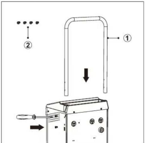
6 Assembly
6.1 Assemble handle
Assemble parts as shown.
| Part Name | |
| 1 | 1x trolley handle |
| 2 | 4x handle screws |
-
Insert the handle into the handle slot.
-
There are 2x screw holes on each side of the handle slot. Fasten the screws to secure the handle in the slot.
6.2 Wheels
6.2.1 Wheel parts
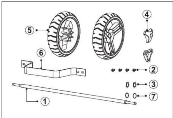
| Part Name | |
| 1 | 1x wheel axle |
| 2 | 4x stand screws |
| 3 | 2x c-clips (for axle) |
| 4 | 2x wheel hub caps |
| 5 | 2x wheels |
| 6 | 1x trolley stand |
| 7 | 2x wheel bearing hub washer |
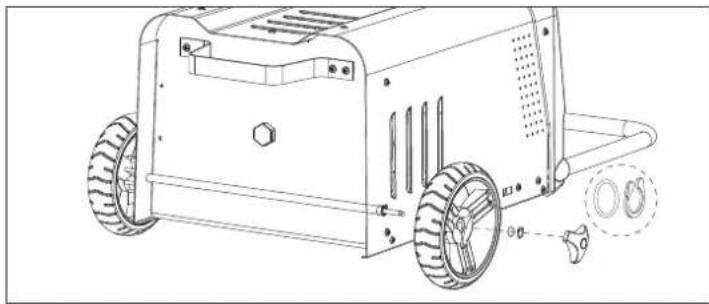
6.2.2 Assemble wheels
Assemble parts as shown.
natural_image
Technical line drawing of a wheeled industrial machine with visible wheels and mounting holes (no text or symbols)7 Getting started
7.1 Check battery compatibility
- Check the battery information marked on the battery label.
Check if the battery type is supported by this product. See: Technical data [▶ 6].
7.2 Prepare vehicle and battery
■ Switch accessory loads OFF (e.g., air conditions, lights, radio).
■ Disconnect / switch OFF items connected to auxiliary power outlets (e.g., GPS, cameras).
■ Remove the key from the ignition.
- Allow vehicle parts to completely cool down.
■ Make sure battery terminals are clean.
8 Connection
Important:
Observe the following information when connecting or disconnecting tester leads to a battery.

WARNING: Risk of electric shock. Disconnect the product from the power supply before connecting or disconnecting leads to the battery.
8.1 Connecting cables to battery
Preconditions:
√ Battery contact terminals are clean.
√ Vehicle engine and electrics are switched OFF.
√ The product is disconnected from the power supply.
1. Connect the red (+) clamp to the positive (+) battery terminal.
2. Connect the black (-) clamp to the negative (-) battery terminal.
3. Wiggle the clamps back and forth to ensure good contact.
Note:
Refer to the vehicle manufacturer instructions for alternative connection points.
8.2 Disconnecting cables from battery
- Disconnect the product from the power supply.
- Disconnect the black (-) clamp to the negative (-) battery terminal.
- Disconnect the red (+) clamp to the positive (+) battery terminal.
9 Operation
9.1 Charging batteries

WARNING: Explosive gases. Prevent flames and sparks. Provide adequate ventilation during charging.
natural_image
Simple line drawing of a person holding a plug with a bulb, no text or symbols present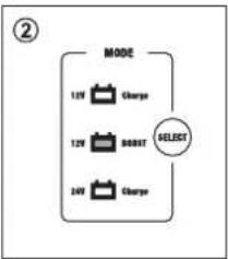
flowchart
graph TD
    A["MODE"] --> B["12V Charge"]
    A --> C["12V BOOT"]
    A --> D["24V Charge"]
    E["SELECT"] --> A
flowchart
graph TD
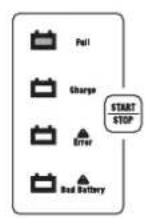
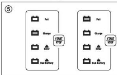
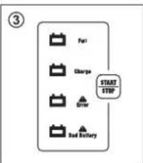
A["Start/Stop"] --> B["Pull"]
A --> C["Charger"]
A --> D["Driver"]
A --> E["Bed Battery"]
flowchart
graph TD
    A["TYPE"] --> B["STD"]
    A --> C["ACK"]
    A --> D["SEL"]
    E["SELECT"] --> A
Preconditions:
√ The product is not connected to the power supply.
√ You have checked the battery rating plate for compatibility (battery type and voltage).
- Connect the product to the battery. See: Connecting cables to battery [▶ 5].
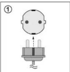
- Connect the product to the power supply.
→ The display will show the battery voltage. - Press the "MODE" SELECT button to choose "12V Charge" or "24V Charge".
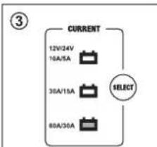
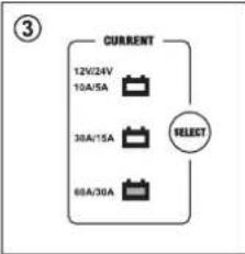
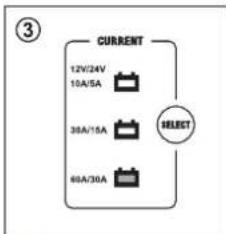
- Press the "CURRENT" SELECT button to choose "12V (10A, 30A, 60A)" or "24V (5A, 15A, 30A)".
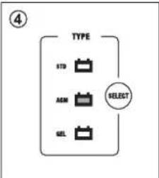
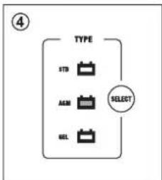
- Press the "TYPE" SELECT button to choose a battery type "STD", "AGM", or "GEL".
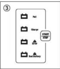
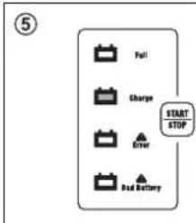
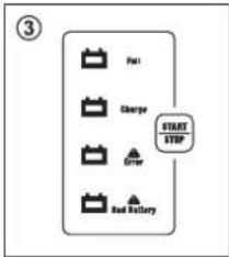
- Press the START|STOP button to start/stop charging.
- When charging is complete, disconnect the product from the power supply.
- Disconnect the product from the battery. See: Disconnecting cables from battery [▶ 5].
9.2 Jumpstarting
Notes:
- The jump start function can be used to help start vehicles with a weak battery.
- In very low temperatures or if the battery voltage reading on the display is below 8.5 V, it is recommended to charge the battery at least 5 minutes before attempting to jump start.
natural_image
Simple diagram of a human head with a plug and screw base, no text or symbols present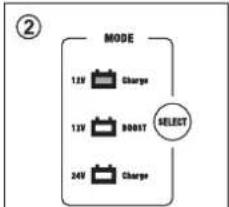
flowchart
graph TD
    A["MODE"] --> B["12V Charge"]
    A --> C["13V BOOST"]
    A --> D["24V Charge"]
    E["SELECT"] --> A
flowchart
graph TD
    A["CURRENT"] --> B["12V/24V"]
    A --> C["16A/35A"]
    A --> D["36A/15A"]
    A --> E["80A/36A"]
    F["SELECT"] --> A
- Connect the product to the battery. See: Connecting cables to battery [▶ 5].
- Press the "MODE" SELECT button to enter "12 V BOOST" mode.
- Press the START|STOP button to start boosting.
→ The display will show the countdown time.
→ The product will deliver a 30 A charge until the engine starts.
- Try to start the vehicle using the ignition switch.
Do not hold the ignition switch ON for more than 5 seconds at a time.
To prevent damage caused by overheating, boosting will automatically stop after approx. 5 seconds. To prevent overheating, the product will not operate for 3 minutes after boosting for cooling down.
→ Wait approximately 3 minutes before trying to start the engine again.
- If the engine starts, let it run for a sufficient time to allow the battery to recharge.
→ If you cannot start the vehicle, consult a qualified professional.
-
Disconnect the product from the battery. See: Disconnecting cables from battery [▶ 5].
-
Disconnect the product from the power supply.
10 Replace fuses

WARNING: Always disconnect the product from batteries and the power supply before replacing the fuse.
Preconditions:
√ The product is connected to the power supply and battery.
When attempting to charge the display shows: "0 V" and "ERROR".
-
Disconnect the product from the power supply.
-
Disconnect the product from the battery. See: Disconnecting cables from battery [▶ 5].
-
Refer to the following diagram for information about how to replace a blown fuse. For information about the fuse type, see: Technical data [▶ 6].
→ Always replace a fuse with the same type and specification.
11 Troubleshooting
| Problem Possible cause Suggested solution | ||
| "Error" indicator lights up and a buzzer sounds | Clamps are connected in reverse (incorrect polarity) | Connect the clamps correctly |
| Battery voltage is below 1 V Check | if clamps are connected correctly and/or replace battery | |
| 12 V mode is selected for a 24 V battery system | Change to 24 V mode | |
| "Bad Battery" indicator lights up and a buzzer sounds | Connected battery voltage is between 1 V to 4 V | Replace the battery |
| During charging / starting process, the display returns to standby and shows battery voltage | Charger has overheated Switch product OFF and allow to completely cool down before using again | |
| Clamps are loose Check the clamps are connected correctly | ||
| There is a short or open circuit Check the clamps are connected correctly | ||
| When attempting to charge a battery the display shows "θ v" and the "Error" indicator lights up | The fuse has blown See section: Replace fuses [▶6] | |
12 Cleaning
Important:
- Do not use aggressive cleaning agents, rubbing alcohol or other chemical solutions. They damage the housing and can cause the product to malfunction.
-
Do not immerse the product in water.
-
Disconnect the product from the power supply.
- Disconnect any batteries.
- Let the product cool down to ambient temperature.
- Clean the product with a dry, fibre-free cloth.
13 Disposal

This symbol must appear on any electrical and electronic equipment placed on the EU market. This symbol indicates that this device should not be disposed of as unsorted municipal waste at the end of its service life.
Owners of WEEE (Waste from Electrical and Electronic Equipment) shall dispose of it separately from unsorted municipal waste. Spent batteries and accumulators, which are not enclosed by the WEEE, as well as lamps that can be removed from the WEEE in a non-destructive manner, must be removed by end users from the WEEE in a non-destructive manner before it is handed over to a collection point.
Distributors of electrical and electronic equipment are legally obliged to provide free take-back of waste.
Conrad provides the following return options free of charge (more details on our website):
in our Conrad offices
at the Conrad collection points
at the collection points of public waste management authorities or the collection points set up by manufacturers or distributors within the meaning of the ElektroG
End users are responsible for deleting personal data from the WEEE to be disposed of.
It should be noted that different obligations about the return or recycling of WEEE may apply in countries outside of Germany.
14 Technical data
14.1 Product
Input 220 - 240 V/AC, 50-60Hz 13 A max.
Output 12 V/DC: 10 A, 30 A, 60 A
24 V/DC: 5 A, 15 A, 30 A
Jump starting.... 12 V/DC, 200 A
Duty cycle: 5 secs ON / 180 secs OFF
Charging voltage (max.) 12 V: AGM-14.7 V, GEL-14.1 V, STD-14.4 V
24 V: AGM-29.4 V, GEL-28.2 V, STD-28.8 V
Recommended battery capacities ..... 10 - 600 Ah
Fuse....2x 80 A
Air circuit breaker....>16 A
Ingress protection.... IP20
Supported battery types .... Lead-acid: STD (WET, MF), AGM, GEL
Protection .... Over-charge, overheat, reverse polarity (incorrect connection), short circuit (defective battery), excess current
14.2 Environment
Operating conditions....-20 to +40 °C, 10 - 85 % RH (non-condensing)
Storage conditions....-30 to +70 °C, 10 - 95 % RH (non-condensing)
14.3 Other
Cable length 1.9 m
Dimensions (W x H x D) 279 x 800 x 390 mm
Weight 16 kg
This is a publication by Conrad Electronic SE, Klaus-Conrad-Str. 1, D-92240 Hirschau (www.conrad.com).
All rights including translation reserved. Reproduction by any method (e.g. photocopying, microfilming or the capture in electronic data processing systems) requires prior written approval from the editor. Reprinting, also in part, is prohibited. This publication reflects the technical status at the time of printing.
Copyright by Conrad Electronic SE.
*2472503_V2_0123_dh_mh_en 9007199882313355-2 I2/O2 en
VOLTCRAFT
F Mode d'emploi
VC-WL 60/200
natural_image
Technical line drawing of a wheeled robotic vehicle with wheels and mounting brackets (no text or symbols)7 Démarrage
natural_image
Simple line drawing of a person holding a plug with a screw base, no text or symbols present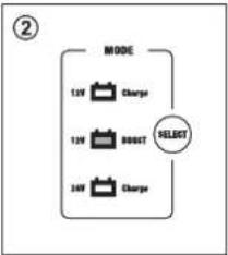
flowchart
graph TD
    A["MODE"] --> B["12V Charge"]
    A --> C["13V RESET"]
    A --> D["24V Charge"]
    B --> E["SELECT"]
    C --> E
    D --> E
flowchart
graph TD
    A["Fuel"] --> B["Charger"]
    B --> C["Driver"]
    C --> D["Bed Inventory"]
    D --> E["START/STOP"]
flowchart
graph TD
    A["TYPE"] --> B["STD"]
    A --> C["AGM"]
    A --> D["SEL"]
    E["SELECT"] --> A
flowchart
graph TD
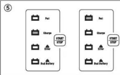
A["Start STOP"] --> B["Full"]
A --> C["Charge"]
A --> D["Driver"]
A --> E["Bed Battery"]
F["Start STOP"] --> G["Full"]
F --> H["Charge"]
F --> I["Driver"]
F --> J["Bed Battery"]
natural_image
Simple diagram of a person holding a plug with pins, no text or symbols present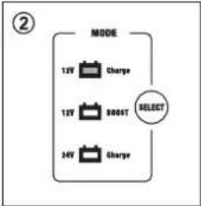
flowchart
graph TD
    A["MODE"] --> B["12V Charge"]
    A --> C["15V 800T SELECT"]
    A --> D["34V Charge"]
Copyright by Conrad Electronic SE.
*2472503_V2_0123_dh_mh_fr 9007199882313355-3 I2/O2 en
VOLTCRAFT
natural_image
Technical line drawing of a wheeled robotic vehicle with visible wheels and mounting holes (no text or symbols)7 Aan de slag
natural_image
Simple line drawing of a baby head with a plug and base, no text or symbols present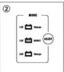
flowchart
graph TD
    A["MODE"] --> B["12V Charge"]
    A --> C["12V 800T SELECT"]
    A --> D["24V Charge"]
flowchart
graph TD
    A["Start/Stop"] --> B["Drive"]
    B --> C["Charge"]
    C --> D["Fail"]

flowchart
graph TD
    A["TYPE"] --> B["STD"]
    A --> C["A&M"]
    A --> D["GEL"]
    E["SELECT"] --> A
flowchart
graph TD
    A["Full"] --> B["Charge"]
    B --> C["Error"]
    C --> D["Bed Battery"]
    E["START STOP"] --> F["Full"]
    G["Start STOP"] --> H["Charge"]
    I["Start STOP"] --> J["Error"]
    K["Start STOP"] --> L["Bed Battery"]
Voorwaarden:
natural_image
Simple line drawing of a baby head with a plug and screw base, no text or symbols present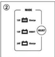
flowchart
graph TD
    A["MODE"] --> B["12V Charge"]
    A --> C["12V RESET"]
    A --> D["24V Charge"]
    E["SELECT"] --> A
flowchart
graph TD
    A["12V/24V\n10A/5A"] --> B["Current"]
    C["38A/15A"] --> B
    D["68A/30A"] --> B
    E["SELECT"] --> B
Copyright by Conrad Electronic SE.
*2472503_V2_0123_dh_mh_nl 9007199882313355-4 I2/O2 en


- Erste Schritte
- Fehlersuche
- VOLTCRAFT
- Intended use
- Delivery contents
- Latest product information
- Description of symbols
- Safety instructions
- Read first!
- General
- Handling
- Operating environment
- Operation
- Mains cable
- Connected devices
- Product
- Working with rechargeable batteries
- Assembly
- Assemble handle
- Wheels
- Assemble wheels
- Getting started
- Check battery compatibility
- Prepare vehicle and battery
- Connection
- Important:
- Connecting cables to battery
- Note:
- Disconnecting cables from battery
- Operation
- Charging batteries
- Jumpstarting
- Notes:
- Replace fuses
- Cleaning
- Disposal
- Technical data
- Product
- Environment
- Other
- Démarrage
- Aan de slag
Brand : VOLTCRAFT
Model : VC-WL 60/200
Category : Battery charger