
PerfectView CAM 29BK NAV - Rear Camera DOMETIC - Free user manual and instructions
Find the device manual for free PerfectView CAM 29BK NAV DOMETIC in PDF.

| Product type | Video rear view camera |
| Brand | Dometic |
| Model | PerfectView CAM 29BK NAV (ref. 9600000051) |
| Camera dimensions | 26 x 17 mm (L x D) |
| Mounting socket dimensions | 36 x 25 mm |
| Weight | 40 g |
| Power supply | 12 V (DC), 60 mA |
| Image sensor | 1/4" CMOS |
| Resolution | > 270,000 pixels |
| Horizontal viewing angle | approx. 115° |
| Vertical viewing angle | approx. 90° |
| Lens opening angle (diagonal) | 150° |
| Video standard | NTSC, 1 Vpp |
| Photosensitivity | 0.5 Lux |
| Operating temperature | from -20 °C to +70 °C |
| Protection type | IP67 |
| Length of supplied cable | 10 m |
| Available accessories | Extension cable 5 m (ref. 9103555986), extension 20 m (ref. 9600000203) |
| Care and cleaning | Clean with a damp cloth; do not use high-pressure cleaner, do not open, do not pull on cables |
| Safety | Securely fasten parts, follow vehicle manufacturer's instructions, insulate electrical connections, do not drill without checking |
| Reparability | In case of defect, contact the manufacturer's subsidiary or specialized dealer; spare parts not listed, accessories available |
| Warranty | Legal, with presentation of invoice and description of defect |
| General information | Manual available in several languages (FR, EN, DE, etc.); installation recommended by a specialist |
Frequently Asked Questions - PerfectView CAM 29BK NAV DOMETIC
User questions about PerfectView CAM 29BK NAV DOMETIC
0 question about this device. Answer the ones you know or ask your own.
Ask a new question about this device
Download the instructions for your Rear Camera in PDF format for free! Find your manual PerfectView CAM 29BK NAV - DOMETIC and take your electronic device back in hand. On this page are published all the documents necessary for the use of your device. PerfectView CAM 29BK NAV by DOMETIC.
USER MANUAL PerfectView CAM 29BK NAV DOMETIC
natural_image
Technical line drawing of a mechanical connector with coiled cable and housing (no text or symbols)CAM29N
EN
Rear View Video Camera
Installation and Operating Manual ..... 6
DE
Rückfahrvideokamera
natural_image
Technical line drawing of a welding process with arrows indicating motion (no text or symbols)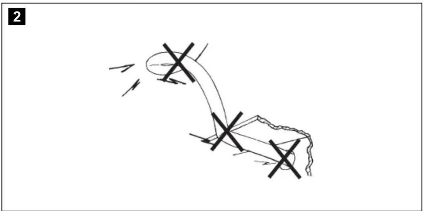
natural_image
Simple line drawing of a mechanical or electrical component with no text, numbers, or symbols3
4
Please read this instruction manual carefully before installation and first use, and store it in a safe place. If you pass on the product to another person, hand over this instruction manual along with it.
Table of contents
1 Explanation of symbols....6
2 Safety and installation instructions....7
3 Scope of delivery 8
4 Accessories/add-ons....8
5 Intended use....8
6 Technical description 9
7 Installing the reversing video camera 9
8 Connecting electrical power to the reversing video camera ..... 11
9 Checking the function and adjusting the camera ..... 12
10 Maintaining and cleaning the reversing video camera 12
11 Troubleshooting....12
12 Warranty 12
13 Disposal....12
14 Technical data....13
1 Explanation of symbols

WARNING!
Safety instruction: Failure to observe this instruction can cause fatal or serious injury.

CAUTION!
Safety instruction: Failure to observe this instruction can lead to injury.

NOTICE!
Failure to observe this instruction can cause material damage and impair the function of the product.

NOTE
Supplementary information for operating the product.
2 Safety and installation instructions
The manufacturer accepts no liability for damage in the following cases:
• Faulty assembly or connection
- Damage to the product resulting from mechanical influences and excess voltage
• Alterations to the product without express permission from the manufacturer
- Use for purposes other than those described in the operating manual
Please observe the prescribed safety instructions and stipulations from the vehicle manufacturer and service workshops.
Observe the following installation instructions:

CAUTION!
- Secure the parts installed in the vehicle to ensure they cannot become loose under any circumstances (sudden braking, accidents) and cause injuries to vehicle occupants.
- Always follow the safety instructions of the vehicle manufacturer. Some work (e.g. on retention systems such as the AIRBAG etc.) may only be performed by qualified specialists.

NOTICE!
- To prevent damage when drilling, make sure there is sufficient space on the other side for the drill head to emerge.
- Deburr all drill holes and treat them with a rust-protection agent.
Observe the following instructions when working with electrical parts:

NOTICE!
- Only use a diode test lamp or voltmeter to test voltages in electric cables. Test lamps with a bulb consume too much voltage, which can damage the vehicle's electronic system.
- When routing the electrical connections, ensure that:
- They are not kinked or twisted
- They do not rub on edges
- They are not laid in sharp-edged ducts without protection.
• Insulate all connections.
- Secure the cables against mechanical wear by using cable binders or insulating tape, for example on existing cables.
The camera is waterproof, however, you should observe the following instructions when handling the camera:

NOTICE!
- Do not spray the camera directly with a high-pressure cleaning device.
- Do not open the camera, as this impairs the leak-tightness and the function of the camera.
- Do not pull at the cables, as this impairs the leak-tightness and the function of the camera.
- The camera is not suitable for submerged operation.
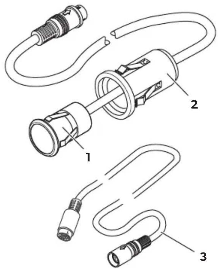
3 S c o p e o f d e l


Designation Ref. no.
11 Camera 9600000051
21 Installation sleeve
31 Connection cable, 10 m long
- - Fastening material
4 Accessories/add-ons
| Designation | Ref. no. |
| Extension cable, 5 m | 9103555986 |
| Extension cable, 20 m | 9600000203 |
5 l n t e n d e d u s
The CAM29N camera (ref. no. 9600000051) is suitable for reversing video systems used in vehicles.
Reversing video systems support the driver when reversing, however this does not relieve you of the obligation to take proper care when reversing.
6 Technical description
The CAM29N camera can be used for many different purposes, for example:
- As a reversing video camera for vehicles for installation in the bumper
• As a side camera in an HGV - As entrance monitors in buses
- For hidden indoor surveillance.
The CAM29N reversing video camera is comprised of a camera and the mounting case for optional installation.
The camera can be installed directly, for example in a bumper.
The power is connected using a cable ready to plug into the monitor.
7 Installing the reversing video camera

NOTE
If you do not have sufficient technical knowledge to install and connect the components in vehicles, you should have a specialist install the reversing video camera in your vehicle.
7.1 Installing the camera
Observe the following information when selecting an installation location for the camera:
- Note the length of the camera cable.
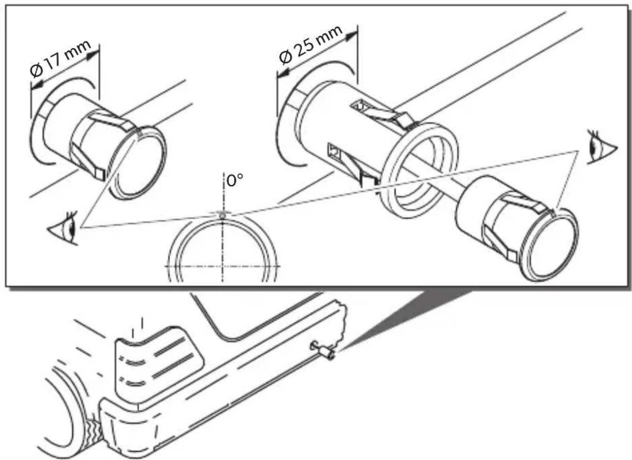
- If you wish to use the camera as a reversing video camera, installing the camera in the middle of the bumper is recommended (fig. 4, page 4).
The installation location on the bumper should be perpendicular to the road surface to ensure the camera is aligned horizontally.
The camera has a 90^ horizontal field of view. Due to the field of view, the reversing video camera can only detect objects near the corner of the vehicle to a limited extent.
The following section describes the procedure for installing the reversing video camera in the bumper. You can also install the camera in other positions, depending on how you wish to use it.

NOTE
The installation sleeve provided (fig. 3, 2, page 4) is not required for the installation procedure described here.
▶Select a suitable installation location.

NOTICE!
Before drilling any holes, ensure that no electrical cables or other parts of the vehicle can be damaged by drilling, sawing and filing.
▶Drill a hole in the bumper with a diameter of 17 mm.
▶ Guide the camera with the socket at the front into the drill hole as far as it will go. Make sure that the camera is aligned correctly.

NOTE
Make sure it is correctly aligned. If the camera is not correctly aligned, the picture will be askew or upside down on the monitor.
▶Check that the camera is installed securely.
It must be firmly seated and may not fall out of the drill holes due to vibrations.
7.2 Laying cables

NOTICE!
Before drilling any holes, ensure that no electrical cables or other parts of the vehicle can be damaged by drilling, sawing and filing.

NOTE
- As far as possible, use original ducts for laying the cables, or other suitable options such as panelling edges, ventilation grilles or dummy plugs. If there is no rubber plug, produce a suitable hole with a diameter of around 13 mm and insert a cable bushing sleeve.
- Cables and connections that are not properly installed will cause malfunctions or damage to components. Correct installation of cables and connections ensures lasting and trouble-free operation of the retrofitted components.
Therefore, please observe the following instructions:
- Wherever possible, lay cables inside the vehicle, as they are better protected there than outside.
If you do need to lay a cable outside the vehicle, ensure that it is well fastened (use additional cable ties, insulating tape etc.). - To prevent damage to the cables when laying them, ensure that they are far enough away from hot or moving vehicle components (exhaust pipes, drive shafts, light systems, fans, heaters, etc.).
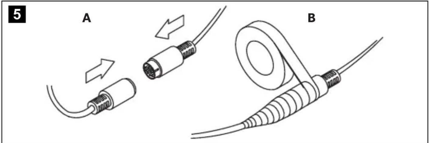
- Wrap good-quality insulating tape around the plug connections of the connecting cables and every connection on a cable (including inside the vehicle) to ensure no water can penetrate them (fig. 5 page 5). The most suitable tape for this is self-vulcanising tape, e.g. made by 3M.
- When laying the cables, make sure:
– They are not kinked or twisted
– They do not rub on edges
- They are not laid in sharp-edged ducts without protection (fig. 2, page 3).
- Attach the cables securely in the vehicle with cable binders, insulating tape or by glueing them to prevent them from being tripped over.
- Protect every through-hole made in the outer skin of the bodywork against water penetration, for example by using a cable with a sealant and by spraying the cable and the cable sleeve with sealant.

NOTE
- Only start sealing through-holes when you have completed all installation work on the camera and have laid the required cable lengths.
- Pull the socket connector of the camera cable through the cable bushing sleeve before inserting the sleeve in the bodywork.
Route the camera cable into the interior of the vehicle so that it cannot be damaged under any circumstances (e.g. by gravel impact).
▶ Lay the camera cable so that should you need to remove the camera, you can easily access the plug connection.
This facilitates the disassembly considerably.
8 Connecting electrical power to the reversing video camera
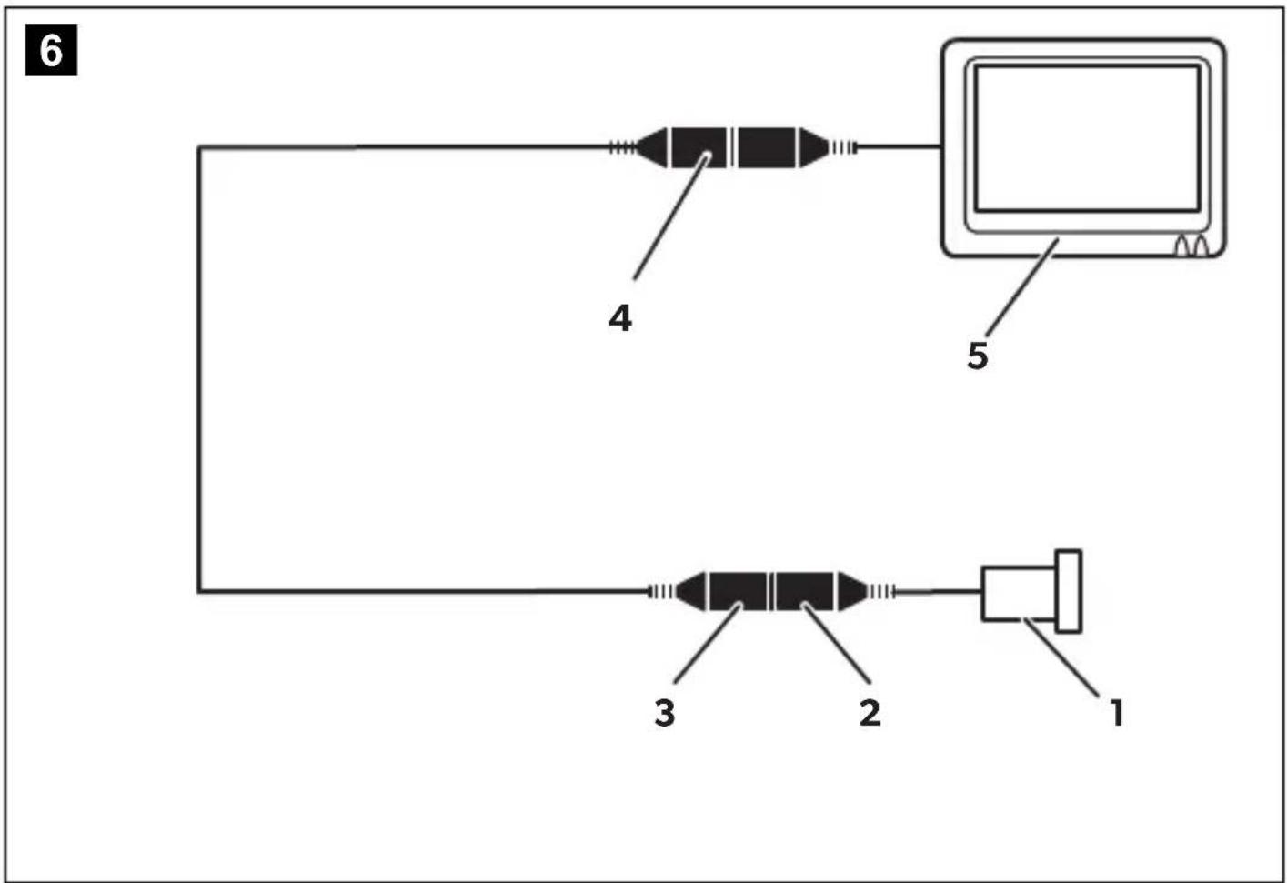
The circuit diagram for the reversing video camera can be found in fig. 6, page 5.
Connecting the camera

NOTE
Make sure the plug connections are assembled in such a way that the arrows on the plug and the socket are pointing at each other (fig. 5, page 5).
▶ Insert the plug of the camera cable (fig. 6 2, page 5) as far as it will go into the 6-pin socket (fig. 6 3, page 5) of the connection cable.
Make sure that the plastic cap of the socket reaches up to the arrow on the plug.
▶ Connect the 6-pin plug (fig. 6 4, page 5) on the connection cable to the monitor.
9 Checking the function and adjusting the camera
▶Check the function of the camera after you have connected it to a monitor.
▶ Use the monitor picture to align the camera if necessary so that the picture on the monitor is horizontal.
10 Maintaining and cleaning the reversing video camera

NOTICE!
Do not use sharp or hard objects or cleaning agents for cleaning as these may damage the product.
▶Occasionally clean the product with a damp cloth.
11 Troubleshooting
The monitor ceases to display camera images.
The camera or the monitor may not be properly connected.
▶ Check all plug connections between the camera and the monitor.
▶Ensure that the monitor is supplied with power.
12 Warranty
The statutory warranty period applies. If the product is defective, please contact the manufacturer's branch in your country (see the back of the instruction manual for the addresses) or your retailer.
For repair and guarantee processing, please include the following documents when you send in the device:
• A copy of the receipt with purchasing date
- A reason for the claim or description of the fault
13 Disposal
Place the packaging material in the appropriate recycling waste bins wherever possible.

If you wish to finally dispose of the product, ask your local recycling centre or specialist dealer for details about how to do this in accordance with the applicable disposal regulations.
14 Technical data
| PerfectView CAM29N | |
| Ref. no.: 9600000051 | |
| Operating voltage: 12 V--- | |
| Current: 60 mA | |
| Image sensor 1⁄4" CMOS sensor | Preset mirror image function |
| Lens: 150° opening angle, diagonal | |
| Pixels: >270 000 pixels | |
| Video standard: NTSC, 1 Vpp | |
| Light sensitivity: 0.5 lux | |
| Operating temperature: -20 °C to +70 °C | |
| Horizontal picture angle: approx. 115° | |
| Vertical picture angle: | approx. 90° |
| Protection class: | Equivalent to IP 67 |
| Dimensions (L x D) | |
| Camera: | 26 x 17 mm |
| Installation sleeve: | 36 x 25 mm |
| Weight: | 40 g |
Approvals

6 Description technique
dometic.com/sales-offices


- CAM29N
- Table of contents
- Explanation of symbols
- WARNING!
- CAUTION!
- NOTICE!
- NOTE
- Safety and installation instructions
- Please observe the prescribed safety instructions and stipulations from the vehicle manufacturer and service workshops.
- Accessories/add-ons
- Technical description
- Installing the reversing video camera
- Installing the camera
- Laying cables
- Connecting electrical power to the reversing video camera
- Connecting the camera
- Checking the function and adjusting the camera
- Maintaining and cleaning the reversing video camera
- Troubleshooting
- The monitor ceases to display camera images.
- Warranty
- Disposal
- Approvals
- Description technique
Brand : DOMETIC
Model : PerfectView CAM 29BK NAV
Category : Rear Camera