DWA-01D - Wireless Adapter SONY - Free user manual and instructions
Find the device manual for free DWA-01D SONY in PDF.

| Product Type | Wireless Adapter |
| Brand | Sony |
| Model | DWA-01D |
| Dimensions (W x H x D) | 144 x 88 x 31.5 mm |
| Weight | Approx. 330 g |
| Power Supply | 12 V DC (10 V to 17 V DC) |
| Audio Output Connectors | OUTPUT1 (analog, 4-pin), OUTPUT2 (analog/digital AES3, 4-pin) |
| Monitor Output | 3.5 mm TRS jack (PHONES) |
| Word Sync Input | BNC-R, 75 ohms impedance |
| Analog Output Impedance | 150 ohms or less |
| Digital Output Impedance | 110 ohms (AES/EBU) |
| Monitor Output Level | 50 mW (16 ohms load, 1% THD) |
| Compatible Receivers | DWR-S01D (digital), WRR-855 (UHF analog) |
| Main Functions | Mounting on camcorder back, portable wireless receiver, analog/digital audio output, sync input, waterproof structure, combination of two adapters |
| Operating Temperature | 0°C to +50°C |
| Storage Temperature | -20°C to +60°C |
| Maintenance and Cleaning | Soft dry cloth; do not use thinner, benzene, or alcohol |
| Safety | Use away from electrical devices (motor, transformer); avoid prolonged listening at excessive sound pressure |
| Supplied Accessories | DC power cable, mounting plate, audio cables (2), instruction manual, warranty brochure |
| Mounting | V-mount bracket for camcorder; assembly bracket for combining two adapters |
Frequently Asked Questions - DWA-01D SONY
User questions about DWA-01D SONY
0 question about this device. Answer the ones you know or ask your own.
Ask a new question about this device
Download the instructions for your Wireless Adapter in PDF format for free! Find your manual DWA-01D - SONY and take your electronic device back in hand. On this page are published all the documents necessary for the use of your device. DWA-01D by SONY.
USER MANUAL DWA-01D SONY
For Customer in China
Operating Instructions GB
Mode d'emploi FR
①ワイヤレスレシーバースロット
1:GND 2:NC 3:NC 4:+12V
natural_image
Technical line drawing of a mechanical device with a top panel and bottom panel, showing internal components and directional arrows (no text or symbols)ブロックダイヤグラム
flowchart
graph TD
    A["D-Sub15"] --> B["アナログ1"]
    A --> C["アナログ2"]
    A --> D["AES/EBU"]
    A --> E["DC OUT"]
    A --> F["WordSync"]

    B --> G["トランス"]
    C --> H["トランス"]
    D --> I["UNBAL→BAL -40dBu→-58dBu"]
    E --> J["UNBAL→BAL -40dBu→-58dBu"]
    F --> K["DC/DC コンバーター"]
    G --> L["ANALOG AES/EBU"]
    H --> M["リミッター"]
    I --> N["ボリューム"]
    J --> O["MONDAY"]
    K --> P["MONDAY"]
    L --> Q["MONDAY"]
    M --> R["MONDAY"]
    N --> S["MONDAY"]
    O --> T["MONDAY"]
    P --> U["MONDAY"]
    Q --> V["MONDAY"]
    R --> W["MONDAY"]
    S --> X["MONDAY"]
    T --> Y["MONDAY"]
    U --> Z["MONDAY"]
    V --> AA["MONDAY"]
    W --> AB["MONDAY"]
    X --> AC["MONDAY"]
    Y --> AD["MONDAY"]
    Z --> AE["MONDAY"]
故障かなと思ったら
Excessive sound pressure from earphones and headphones can cause hearing loss. In order to use this product safely, avoid prolonged listening at excessive sound pressure levels.
You are cautioned that any changes or modifications not expressly approved in this manual could void your authority to operate this equipment.
For the customers in the U.S.A.
If you have any questions about this product, you may call; Sony Customer Information Service Center 1-800-222-7669 or http://www.sony.com/
Declaration of Conformity
Trade Name: SONY
Model No.: DWA-01D
Responsible Party: Sony Electronics Inc.
Address: 16530 Via Esprillo, San Diego, CA 92127 U.S.A.
Telephone No.: 858-942-2230
This device complies with part 15 of the FCC Rules. Operation is subject to the following two conditions: (1) this device may not cause harmful interference, and (2) this device must accept any interference received, including interference that may cause undesired operation.
All interface cables used to connect peripherals must be shielded in order to comply with the limits for Part 15 of FCC Rules.
For the customers in Canada
Operation is subject to the following two conditions: (1) this device may not cause interference, and (2) this device must accept any interference, including interference that may cause undesired operation of the device.
For the customers in Europe
This product with the CE marking complies with the EMC Directive issued by the Commission of the European Community. Compliance with this directive implies conformity to the following European standard:
• EN301489-1/9/17:
Electromagnetic compatibility and Radio spectrum Matters (ERM)
Electromagnetic Compatibility (EMC) This product is intended for use in the following Electromagnetic Environments: E1 (residential), E2 (commercial and light industrial), E3 (urban outdoors), E4 (controlled EMC environment, ex. TV studio).
The manufacturer of this product is Sony Corporation, 1-7-1 Konan, Minato-ku, Tokyo, Japan.
The Authorized Representative for EMC and product safety is Sony Deutschland GmbH, Hedelfinger Strasse 61, 70327 Stuttgart, Germany. For any service or guarantee matters please refer to the addresses given in separate service or guarantee documents.
Table of Contents
Features ....19
Parts identification ....19
Front/rear/side 19
Bottom 20
Attachment and connections ......22
Attaching the receiver/tuner unit 22
Attaching to/detaching from the camcorder .....22
Combining two DWA-01D adapters ....23
Block diagram 25
Troubleshooting 26
Important notes on operation 28
Notes on using the adapter 28
On cleaning 28
Specifications 28
Features
The DWA-01D wireless adapter allows the optional DWR-S01D digital wireless receiver or the WRR-855 UHF synthesizer tuner unit to be rear-mounted on Sony camcorders. In combination with the DWR-S01D or WRR-855, the DWA-01D can also work as a portable wireless receiver.
Wide array of audio output
To draw its full performance, the DWA-01D comes equipped with a wide range of interfaces. One of the analog audio output connectors can be set to output the AES/EBU digital format signal. A word sync input connector is provided for diverse operational needs.
Monitor output
A monitor output connector is provided to offer easy monitoring of the audio output.
Unique joint mechanism
The DWA-01D is equipped with a joint bracket that allows two DWA-01D adapters to be easily combined. This is particularly convenient when two pairs of the DWR-S01D and DWA-01D are used at the same time as a four-channel receiver system.
Weatherproof structure
By properly mounting the DWR-S01D or WRR-855 on the DWA-01D, a weatherproof structure is obtained.
Parts identification
Front/rear/side
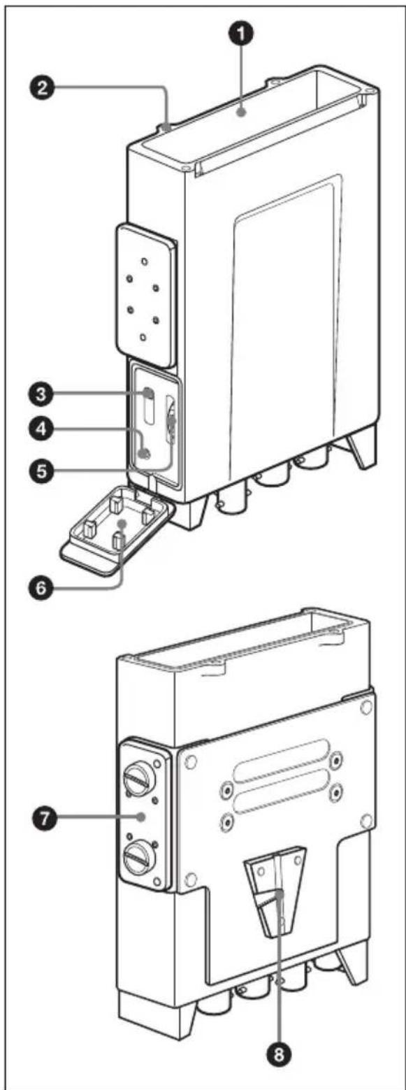
① Wireless receiver slot
Insert the optional DWR-S01D or WRR-855 here.
For details on how to attach the receiver or tuner unit to the DWA-01D, see "Attaching the receiver/tuner unit" on page 22.
② Wireless receiver screw holes
Run in the mounting screws to secure the receiver/tuner unit.
③Monitor output selector
Selects the audio output from the PHONES connector.
1: Outputs the audio from the OUTPUT1 connector to the L/R channels.
1+2: The audio from the OUTPUT1 connector is mixed with the audio from the OUTPUT2 connector (only when the OUTPUT2 connector is set to output analog signal) and output to the L/R channels.
2: Outputs the audio from the OUTPUT2 connector (only when the OUTPUT2 connector is set to output analog signal) to the L/R channels. When the WRR-855 is attached, no audio is output from the PHONES connector.
Note
Monitor output is split from the analog signal output to the OUTPUT1/2 connectors. When audio that is output to the OUTPUT1 connector is changed on the DWR-S01D using the ANALOG OUTPUT1 function, monitor output changes accordingly.
④ PHONES (monitor output) connector (3.5 mm, TRS jack, tip: L, ring: R, sleeve: ground)
Connect the headphones here. Select the output signal using the monitor output selector.
⑤Monitor level control
Adjusts the monitor output level.
⑥Audio monitor section cover
This is a cover for the jack and controls of the audio monitor section. When you do not use the headphones, close this cover.
⑦ Joint bracket
Combines two DWA-01D adapters.
For details on how to combine two DWA-01D adapters, see "Combining two DWA-01D adapters" on page 23.
⑧V-shaped mount bracket
This is a bracket used for attaching to the camcorder.
Bottom
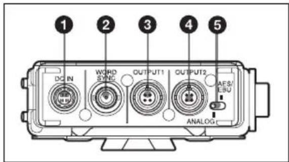
①DC IN (external power input) connector (4-pin)
Connect to the external power output connector of the camcorder using the supplied DC power cable. This connector accepts the power voltage between 10 V DC and 17 V DC.
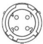
1:GND 2:NC 3:NC 4:+12V
②WORD SYNC (word sync input) connector (BNC type)
Accepts external sync signal.
When the DWR-S01D is attached and the sync signal is input, the DWR-S01D can be operated in synchronization with the whole audio system. In order for the DWR-S01D
to operate in synchronization, select "AUTO" or "EXTERNAL" on the SYNC SOURCE indication of the UTILITY menu of the DWR-S01D. Note that this connector does not work when the WRR-855 is attached.
For details on the frequency of the sync signal, refer to the Operating Instructions supplied with the DWR-S01D.
Note
Even when the 75-ohm termination has been added on the DWR-S01D, this connector still works as the high-impedance input connector while the DWR-S01D is turned off.
③ OUTPUT1 (analog audio output) connector (4-pin)
Outputs balanced analog audio signal. When the DWR-S01D is attached, audio from the tuner 1 or 2 can be selected by using the UTILITY menu of the DWR-S01D. The output from this connector is factory-set to the audio from the tuner 1. When the WRR-855 is attached, audio is output from this connector only.
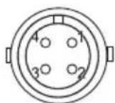
1:NC
2:Hot
3:Cold
4:GND
④ OUTPUT2 (analog/digital audio output) connector (4-pin)
When the DWR-S01D is attached, this connector outputs balanced analog audio signal or AES3-format digital audio signal. Output signal can be selected using the ANALOG AES/EBU selector. When this selector is set to ANALOG, audio from the tuner 2 is output. Note that this connector does not work when the WRR-855 is attached.
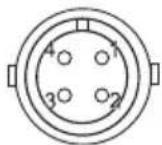
1:NC
2:Hot
3:Cold
4:GND
⑤ANALOG AES/EBU selector
When the DWR-S01D is attached, this selector determines the signal output from the OUTPUT2 connector.
ANALOG: Balanced analog audio signal is output.
AES/EBU: AES3-format digital audio signal is output.
Note that this selector does not work when the WRR-855 is attached.
Attachment and connections
Attaching the receiver/ tuner unit
Insert the DWR-S01D or WRR-855 into the wireless receiver slot.
1 Insert the receiver/tuner unit into the wireless receiver slot after observing the direction of the D-sub 15-pin connector inside the slot and that of the receiver/tuner unit.
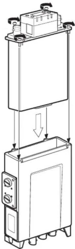
natural_image
Technical line drawing of a mechanical device with internal components and directional arrows indicating assembly (no text or symbols)2 Fasten four mounting screws of the receiver/tuner unit with a screwdriver.
Note
If any of the screws are loose, weatherproof structure may not be obtained or malfunction due to vibration may occur.
Attaching to/detaching from the camcorder
Use the DWA-01D to mount the wireless receiver on the rear of the Sony camcorder. In order to do so, an optional mount bracket (A-8278-057-B) and the mount plate supplied with the DWA-01D are required. To detach the DWA-01D from the mount plate, push the release lever on the mount plate.
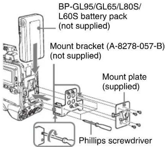
To connect the power cable
Using the DC power cable supplied with the DWA-01D, connect the DC IN connector to the DC OUT connector of the camcorder.
To connect the audio cables
For the camcorder that accepts analog audio only
Use the audio cables supplied with the DWA-01D to connect the OUTPUT1 and 2
connectors to the AUDIO IN connectors of the camcorder.
For the camcorder that accepts digital audio
Set the ANALOG AES/EBU selector to AES/EBU, and connect the OUTPUT2 connector to the AUDIO IN connector of the camcorder using an audio cable supplied with the DWA-01D. Be sure to set the camcorder so that the AUDIO IN connector accepts AES/EBU digital audio signal.
On connecting word clock sync signal and digital audio signal
The DWR-S01D attached to the DWA-01D and the device connected to the DWA-01D through the digital audio interface can be operated properly, under either of the following conditions:
- The device that is connected to the OUTPUT2 connector of the DWA-01D is equipped with a sampling rate converter.
- The DWR-S01D is synchronized with the device that is connected to the DWA-01D using the master word clock signal input to the WORD SYNC connector of the DWA-01D.
There are two types of systems for synchronization using the master word clock signal.
System example 1
The master word clock signal is split using the T-shaped BNC splitter.
One of the devices including the DWR-S01D must be terminated.
For details on how to terminate the word sync signal on the DWR-S01D, refer to the Operating Instructions supplied with the DWR-S01D.
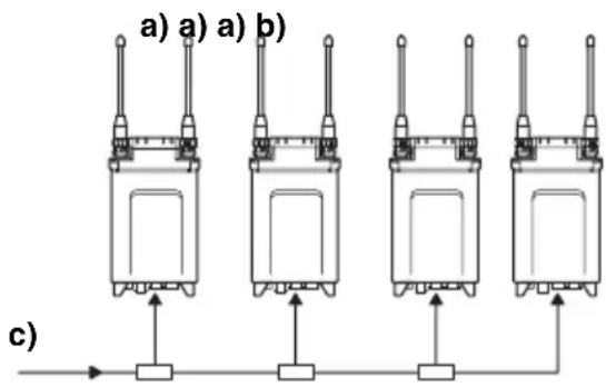
c) Master word clock signal
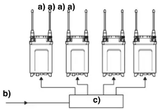
System example 2
The master word clock signal is supplied to each device using the distributor. All the devices must be terminated.
flowchart
graph TD
    A[a) a) a) a) --> C[c)
    B[b) --> C
    C --> A
    C --> B
    style A fill:#f9f,stroke:#333
    style B fill:#f9f,stroke:#333
    style C fill:#ccf,stroke:#333
a) 75-ohm termination setting: ON
b) Master word clock signal
c) Word sync signal distributor
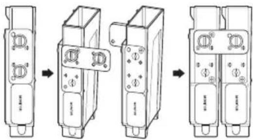
Combining two DWA-01D adapters
Two DWA-01D adapters, each of which a DWR-S01D is attached, can be combined to make a four-channel wireless receiver.
1 Remove four screws from the V-shaped mount bracket and detach the bracket.
Keep the removed screws in the screw holes on the bracket for storage.
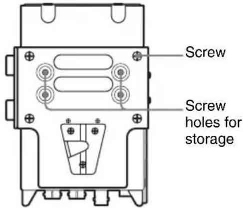
2 Loosen the screws on the joint bracket to remove it from the adapter.
3 Turn the joint bracket 90 degrees and reattach the bracket to the adapter by engaging two holes near the left screw of the bracket with two projections at the side of the adapter.
4 Do step 1 to 3 on the other adapter.
5 Place the adapters so that they show the same side to you. Then, engage the two holes near the right screw of the bracket with two projections at the side of the other adapter. Do the same on the other side, using the bracket on the other adapter. And then, fasten the screws on the brackets to secure the two adapters with each other.
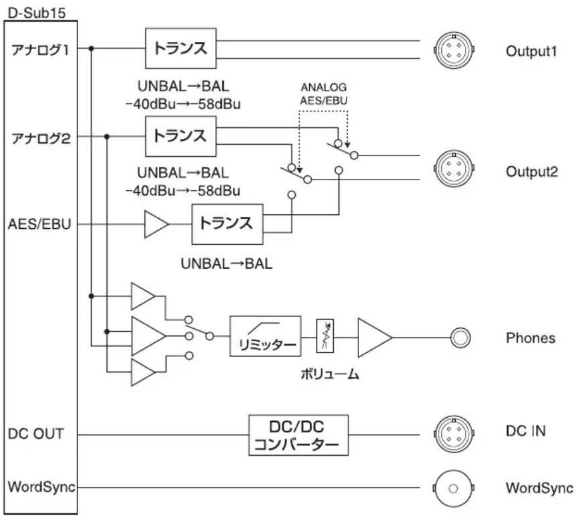
Block diagram
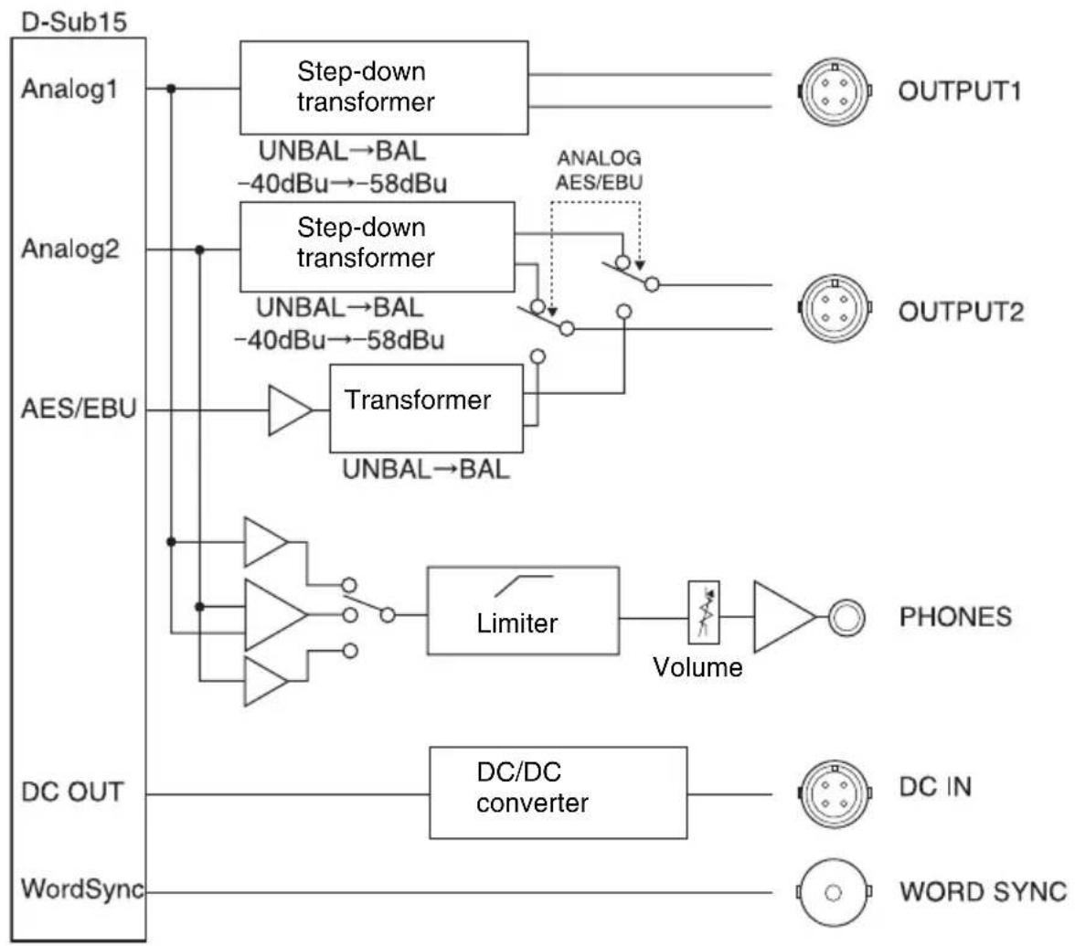
flowchart
graph TD
    A["D-Sub15"] --> B["Analog1"]
    A --> C["Analog2"]
    A --> D["AES/EBU"]
    A --> E["WordSync"]
    B --> F["Step-down transformer"]
    C --> G["Step-down transformer"]
    F --> H["UNBAL→BAL -40dBu→-58dBu"]
    G --> I["UNBAL→BAL -40dBu→-58dBu"]
    H --> J["Transformer UNBAL→BAL"]
    I --> J
    J --> K["Limiter"]
    K --> L["Volume"]
    L --> M["PHONES"]
    E --> N["DC OUT"]
    N --> O["DC/DC converter"]
    O --> P["DC IN"]
    P --> Q["WORD SYNC"]
    style A fill:#f9f,stroke:#333
    style B fill:#ccf,stroke:#333
    style C fill:#ccf,stroke:#333
    style D fill:#ccf,stroke:#333
    style E fill:#cfc,stroke:#333
    style F fill:#ffc,stroke:#333
    style G fill:#ffc,stroke:#333
    style H fill:#ffc,stroke:#333
    style I fill:#ffc,stroke:#333
    style J fill:#ffc,stroke:#333
    style K fill:#ffc,stroke:#333
    style L fill:#cfc,stroke:#333
    style M fill:#cfc,stroke:#333
    style N fill:#cfc,stroke:#333
    style O fill:#cfc,stroke:#333
    style P fill:#cfc,stroke:#333
    style Q fill:#cfc,stroke:#333
Troubleshooting
If you encounter a problem using this adapter, use the following checklist to find a solution. For any problems with the transmitter or receiver, refer to the operating instructions of the respective device. If the problem persists, consult your Sony dealer.
| Symptom Meanings | Remedy | |
| The DWR-S01D or the WRR-855 does not turn on. | The DWR-S01D or the WRR-855 is not correctly inserted into the slot of the camcorder or this adapter. | Insert the DWR-S01D or the WRR-855 until it is firmly and completely in, and then secure it with the mounting screws. |
| There is noise in the analog signal output from the OUTPUT2 connector when the adapter is connected to the device that accepts the analog signal only. | The ANALOG AES/EBU selector is set to AES/EBU. | Set the ANALOG AES/EBU selector to ANALOG. |
| No signal is output from the OUTPUT2 connector when the adapter is connected to the device that accepts the analog signal only. | The tuner 2 of the DWR-S01D is not turned on. | Turn on the tuner 2 of the DWR-S01D. |
| The WRR-855 is attached to the adapter. | The WRR-855 is a single-channel receiver. Thus, there is no signal output from the OUTPUT2 connector. | |
| No signal is output from the OUTPUT2 connector when the adapter is connected to the device that accepts the digital signal. | The ANALOG AES/EBU selector is set to ANALOG. | Set the ANALOG AES/EBU selector to AES/EBU. |
| There is noise in the audio output from the digital device that is connected to the adapter. | The DWR-S01D inserted in the adapter and the digital device that is connected to the adapter are not in synchronization. | If the connected device is not compatible with the asynchronous input (i.e., the sampling rate converter is not equipped), use the word clock signal to synchronize the device. |
| The WORD SYNC connector is not 75-ohm terminated. | When the DWR-S01D that is inserted in the adapter is the end device or when the master word clock signal is input to this adapter only, add the 75-ohm termination to the WORD SYNC connector by using the UTILITY menu of the DWR-S01D. | |
| There is no audio output to the PHONES connector. | The monitor level control is turned down. | Adjust the monitor level by using the monitor level control of the adapter. |
| The tuner that is currently turned off is selected by the monitor output selector. | Check the POWER switch for the corresponding tuner of the DWR-S01D. | |
| The monitor output selector is set to 2 when the WRR-855 is attached to the adapter. | The WRR-855 is a single-channel receiver. Thus, no audio is output when the monitor output selector is set to 2. | |
| When the monitor output selector is set to 1, audio from the tuner 2 is mixed with the audio from the tuner 1. | “RX1+2” is selected on the ANALOG OUTPUT1 function of the DWR-S01D. | On the DWR-S01D, select “RX1” on the ANALOG OUTPU1 function of the UTILITY menu.When “RX1+2” is selected, audio from the tuner 1 and 2 are mixed regardless of the monitor output selection. |
Important notes on operation
Notes on using the adapter
- The Digital Wireless Microphone System product must be used within a temperature range of 0^ to 50^ (32°F to 122°F).
- Operating the adapter near electrical equipment (motors, transformers, or dimmers) may cause it to be affected by electromagnetic induction. Keep the adapter as far from such equipment as possible.
On cleaning
- If the adapter is used in a very humid or dusty place or in a place subject to an active gas, clean its surface as well as the connectors with a dry, soft cloth soon after use. Lengthy use of the adapter in such places or not cleaning it after its use in such places may shorten its life.
- Clean the surface and the connectors of the adapter with a dry, soft cloth. Never use thinner, benzene, alcohol or any other chemicals, since these may mar the finish.
To prevent electromagnetic interference from portable communication devices
The use of portable telephones and other communication devices near the DWA-01D may result in malfunction and interference with audio signals. It is recommended that portable communication devices near the DWA-01D be turned off.
Specifications
Audio section
Audio output connector
SMC9-4S (female) (OUTPUT1/
OUTPUT2)
Analog output impedance
150 ohms or less
AES/EBU output impedance
110 ohms
WORD SYNC input
BNC-R, 75 ohms (when the DWR-S01D is attached to the adapter and 75-ohm termination is added)
Monitor output 3.5 mm TRS jack
Monitor output level
50 mW (16-ohm load, at T.H.D = 1%)
General
Power requirements 12 V DC
Operating voltage 10 V DC to 17 V DC
Operating temperature 0°C to +50°C (+32°F to +122°F)
Storage temperature -20^ to +60^ ( -4^ to +140^ )
Dimensions (unit: mm (inches))

Mass Approx. 330 g (11.6 oz)
Supplied accessories
DC power cable (1)
Mount plate (1)
Audio cable (2)
Operating Instructions (1)
Warranty booklet (1)
Design and specifications are subject to change without notice.
Note
Always verify that the unit is operating properly before use. SONY WILL NOT BE LIABLE FOR DAMAGES OF ANY KIND INCLUDING, BUT NOT LIMITED TO, COMPENSATION OR REIMBURSEMENT ON ACCOUNT OF THE LOSS OF PRESENT OR PROSPECTIVE PROFITS DUE TO FAILURE OF THIS UNIT, EITHER DURING THE WARRANTY PERIOD OR AFTER EXPIRATION OF THE WARRANTY, OR FOR ANY OTHER REASON WHATSOEVER.
Français
AVERTISSEMENT
Identification des parties ....32
1:GND 2:NC 3:NC 4:+12V
natural_image
Technical line drawing of a mechanical device with a top panel and bottom panel, showing internal components and directional arrows (no text or symbols)Schéma fonctionnel
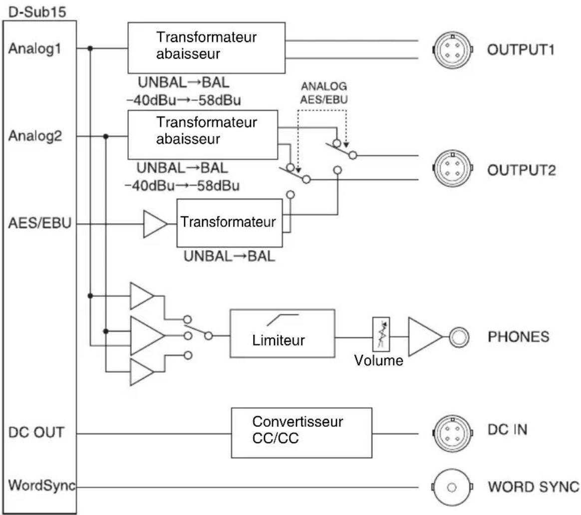
flowchart
graph TD
    A["D-Sub15"] --> B["Analog1"]
    A --> C["Analog2"]
    A --> D["AES/EBU"]
    A --> E["DC OUT"]
    A --> F["WordSync"]

    B --> G["Transformateur abaisseur"]
    C --> H["Transformateur abaisseur"]
    D --> I["Transformateur"]
    E --> J["Convertisseur CC/CC"]
    F --> K["WORD SYNC"]

    G --> L["UNBAL→BAL -40dBu→-58dBu"]
    H --> M["UNBAL→BAL -40dBu→-58dBu"]
    I --> N["Limiteur"]
    J --> O["Volume"]
    K --> P["OUTPUT1"]
    K --> Q["OUTPUT2"]
    K --> R["PHONES"]
    K --> S["DC IN"]
Dépannage
1:GND 2:NC 3:NC 4:+12V
natural_image
Technical line drawing of a mechanical device with internal components and directional arrows indicating assembly (no text or symbols)c) Master-Wordclocksignal
Beispiel System 2
Blockdiagramm
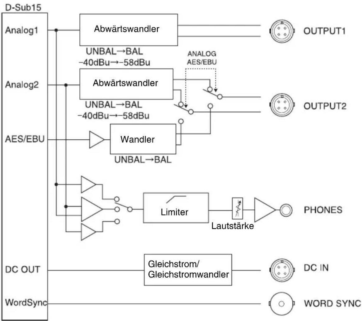
flowchart
graph TD
    A["D-Sub15"] --> B["Analog1"]
    A --> C["Analog2"]
    A --> D["AES/EBU"]
    A --> E["WordSync"]
    B --> F["Abwärtswandler"]
    C --> G["Abwärtswandler"]
    D --> H["Wandler"]
    F --> I["UNBAL→BAL -40dBu→-58dBu"]
    G --> J["UNBAL→BAL -40dBu→-58dBu"]
    H --> K["UNBAL→BAL"]
    F --> L["ANALOG AES/EBU"]
    G --> M["Limiter"]
    M --> N["Lautstärke"]
    N --> O["PHONES"]
    E --> P["Gleichstrom/Gleichstromwandler"]
    P --> Q["DC IN"]
    P --> R["WORD SYNC"]
Fehlerbehebung
natural_image
Technical line drawing of a mechanical device with a top panel and bottom panel, showing internal components and directional arrows (no text or symbols)Diagramma a blocchi
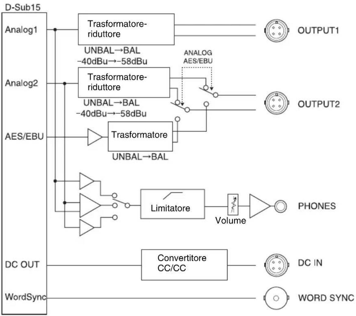
flowchart
graph TD
    A["D-Sub15"] --> B["Analog1"]
    B --> C["Trasformatore-riduttore"]
    C --> D["OUTPUT1"]
    A --> E["Analog2"]
    E --> F["Trasformatore-riduttore"]
    F --> G["ANALOG AES/EBU"]
    G --> H["OUTPUT2"]
    A --> I["AES/EBU"]
    I --> J["Trasformatore UNBAL→BAL"]
    J --> K["Limitatore"]
    K --> L["Volume"]
    L --> M["PHONES"]
    A --> N["DC OUT"]
    N --> O["Convertitore CC/CC"]
    O --> P["DC IN"]
    A --> Q["WordSync"]
    Q --> R["WORD SYNC"]
⑤Selector ANALOG AES/EBU
natural_image
Technical line drawing of a mechanical device with a top panel and bottom panel, showing internal components and directional arrows (no text or symbols)Esquema funcional
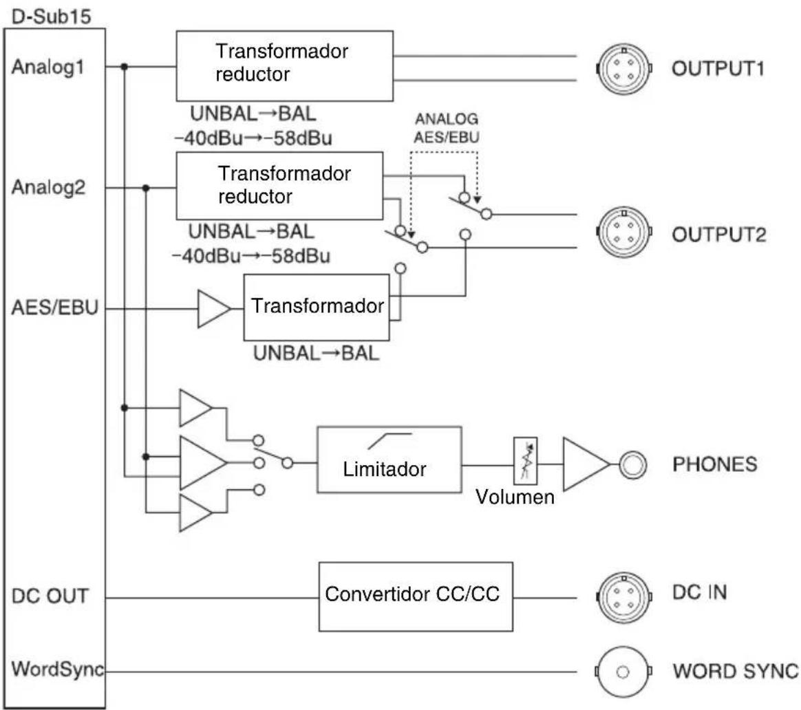
flowchart
graph TD
    A["D-Sub15"] --> B["Analog1"]
    A --> C["Analog2"]
    A --> D["AES/EBU"]
    A --> E["DC OUT"]
    A --> F["WordSync"]

    B --> G["Transformador reductor"]
    G --> H["UNBAL→BAL -40dBu→-58dBu"]
    G --> I["UNBAL→BAL -40dBu→-58dBu"]
    G --> J["ANALOG AES/EBU"]
    J --> K["Transformer"]
    K --> L["UNBAL→BAL"]
    K --> M["Limitador"]
    M --> N["Volumen"]
    N --> O["PHONES"]

    C --> P["Transformador reductor"]
    P --> Q["UNBAL→BAL -40dBu→-58dBu"]
    P --> R["Analog"]
    R --> S["OUTPUT1"]

    D --> T["Transformador"]
    T --> U["UNBAL→BAL"]
    T --> V["Limitador"]
    V --> W["Volumen"]
    W --> X["PHONES"]

    E --> Y["Convertidor CC/CC"]
    Y --> Z["DC IN"]
    Y --> AA["WORD SYNC"]