
AN-01 - TV Antenna SONY - Free user manual and instructions
Find the device manual for free AN-01 SONY in PDF.

| Product Type | Directional UHF TV Antenna |
| Brand | Sony |
| Model | AN-01 |
| Dimensions (without pole) | 343 × 341 × 36 mm (w/h/d) |
| Weight | Approx. 530 g |
| Power supply | DC 9 V or 12 V, current consumption ≤ 100 mA |
| Output connector | BNC-R |
| Frequency range | 470 to 862 MHz |
| Antenna gain | 5 dBi or more |
| Amplifier gain | 18 dB / 10 dB / 0 dB switchable |
| Noise figure | ≤ 6 dB |
| Operating temperature | 0 °C to 50 °C |
| Vertical adjustment angle | 30 degrees |
| Maintenance and cleaning | Clean with a dry, soft cloth. Do not use solvents. |
| Supplied parts | Fixing pole/handle, adapters PF1/2 to W5/8 and W3/8, instruction manual, warranty card |
| Main functions | Wideband directional antenna, built-in amplifier, gain selector, LED indicator, pole or hand mount |
| Compliance | Directive 2014/53/EU (Europe) |
Frequently Asked Questions - AN-01 SONY
User questions about AN-01 SONY
0 question about this device. Answer the ones you know or ask your own.
Ask a new question about this device
Download the instructions for your TV Antenna in PDF format for free! Find your manual AN-01 - SONY and take your electronic device back in hand. On this page are published all the documents necessary for the use of your device. AN-01 by SONY.
USER MANUAL AN-01 SONY
Operating Instructions ____ GB
Before operating the unit, please read this manual thoroughly and retain it for future reference.

For the customers in Europe
Hereby, Sony Corporation declares that this equipment is in compliance with Directive 2014/53/EU.
The full text of the EU declaration of conformity is available at the following internet address:
http://www.compliance.sony.de/
For the customers in the U.S.A. SONY LIMITED WARRANTY -
Please visit http://www.sony.com/psa/warranty for important information and complete terms and conditions of Sony's limited warranty applicable to this product.
For the customers in Canada SONY LIMITED WARRANTY -
Please visit http://www.sonybiz.ca/pro/lang/en/ca/article/resources-warranty for important information and complete terms and conditions of Sony's limited warranty applicable to this product.
For the customers in Europe
Sony Professional Solutions Europe - Standard Warranty and Exceptions on Standard Warranty. Please visit http://www.pro.sony.eu/warranty for important information and complete terms and conditions.
For the customers in Korea SONY LIMITED WARRANTY -
Please visit http://bpeng.sony.co.kr/ handler/BPAS-Start for important information and complete terms and conditions of Sony's limited warranty applicable to this product.
Table of Contents
Overview 18
Identification of Parts and Controls.... 19
Attaching the Antenna ....20
Attaching the Supplied Microphone Stand Attachment Pole/Grip .....20
Attaching to the Microphone Stand 21
Important Notes on Operation.... 22
On Installation 22
On Using the Antenna ....23
On Cleaning 24
Specifications 24
Overview
The AN-01 UHF Antenna is designed to be used with the Sony wireless microphone receiving system. This antenna can be used with both analog system and digital system. The features of this antenna are as follows:
- This wide-band directional antenna uses log-periodic dipole array system that provides improved practical reception sensitivity in its effective directivity, compared to the non-directional antenna.
• Built-in low-noise, low-distortion antenna booster
- Selectable booster gain (18 dB/10 dB/0 dB)
- The grip with screw for attaching to the microphone stand allows this antenna to be attached to the microphone stand or to be hand-held.
- Antenna angle can be adjusted in 30 degrees in vertical direction to allow installation to suit the circumstances.
Identification of Parts and Controls
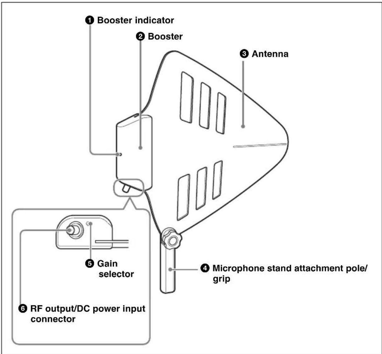
① Booster indicator
Changes the color to show the operation status of the antenna booster.
Red: 18 dB gain
Green: 10 dB gain
Blue: 0 dB gain
② Booster
Amplifies the signal received by the antenna. By using the booster, output signal loss due to a long coaxial cable can be compensated.
The power to the booster is supplied from the device connected to the RF output/DC power input connector.
③ Antenna
Wide-band directional antenna using log-periodic dipole array system.
④ Microphone stand attachment pole/grip
With the PF1/2 screw at the bottom, this antenna can be attached to a microphone stand.
The grip also allows hand-held operation.
For details on how to attach this to the antenna, see "Attaching the Supplied Microphone Stand Attachment Pole/Grip" on page 20.
⑤Gain selector
Switches the antenna booster gain.
REMOTE
18dB
10dB
0dB
REMOTE: The gain switches automatically according to the supplied power voltage as follows:
- When 9 V DC is supplied: 10 dB
- When 12 V DC is supplied: 18 dB
18dB: 18 dB gain regardless of the supplied power voltage
10dB: 10 dB gain regardless of the supplied power voltage
0dB: 0 dB gain regardless of the supplied power voltage
Note
Be sure to supply power to this antenna even when the gain selector is set to "0dB". When no power is supplied, no signal is output from the RF output/DC power input connector.
⑥ RF output/DC power input connector (BNC-R)
Connect to the antenna input connector of the receiver (tuner, tuner base unit, or antenna divider, etc.) to output the signal amplified with the booster. The power is supplied to the booster through this connector.
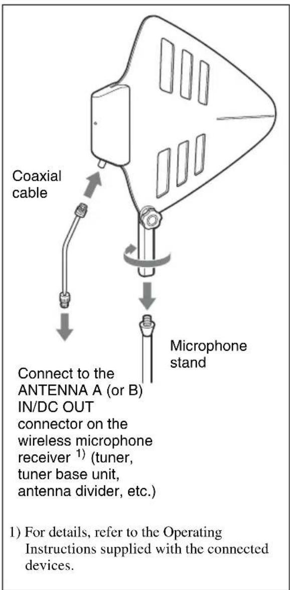
Attaching the Antenna
Attaching the Supplied Microphone Stand Attachment Pole/Grip

To prevent the antenna from coming off the adjusted angle, turn the knob clockwise firmly.
Attaching to the Microphone Stand
Important Notes on Operation
On Installation
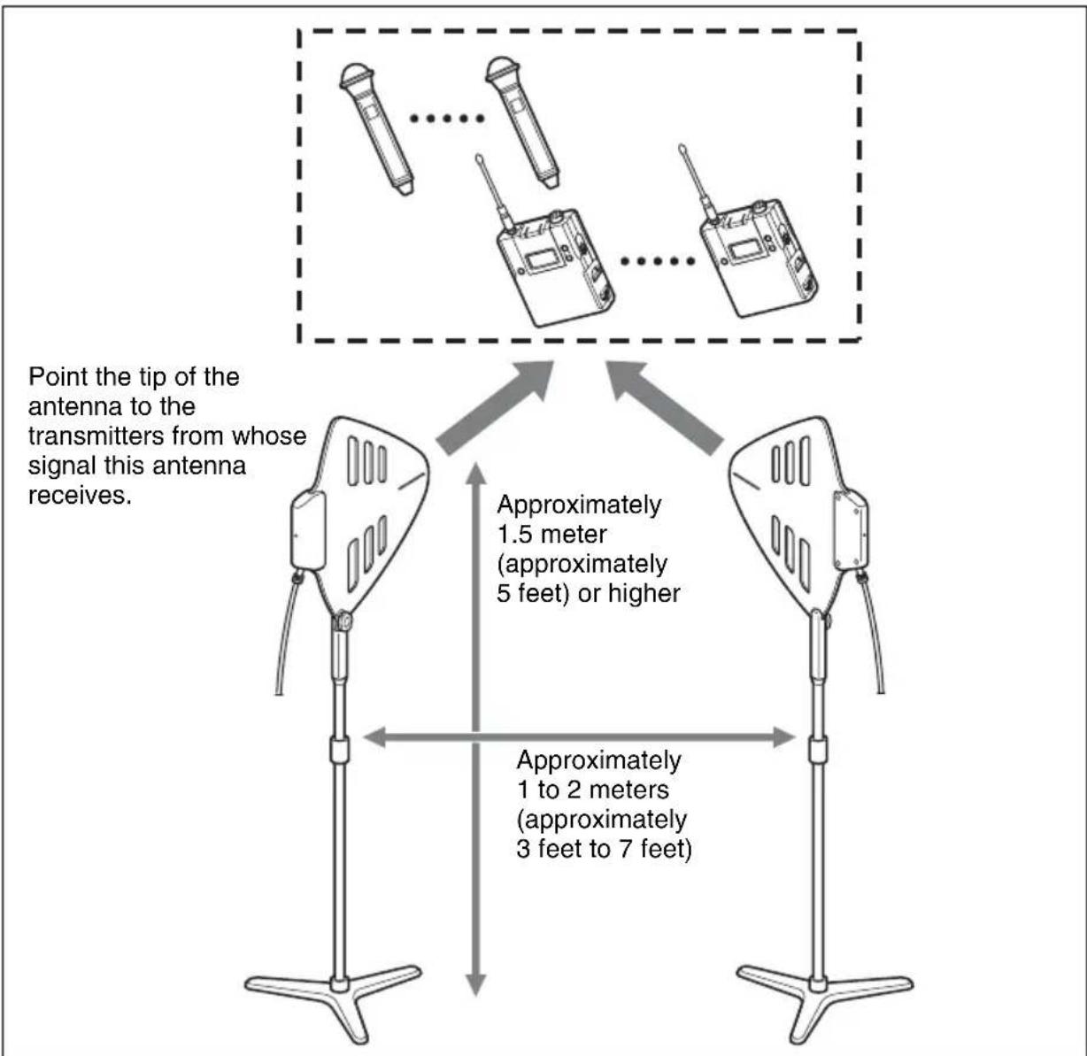
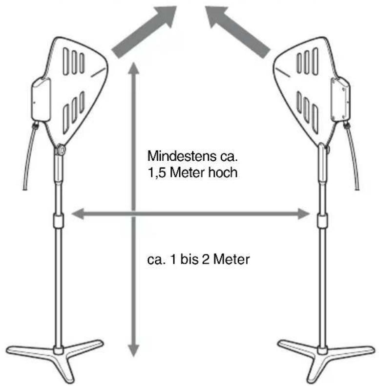
- For diversity signal reception, always use two or more AN-01 units in pairs.
- Note the following when installing this antenna:
flowchart
graph TD
    A["Antenna 1"] -->|Approximately 1.5 meter (approximately 5 feet) or higher| B["Antenna 2"]
    C["Antenna 3"] -->|Approximately 1 to 2 meters (approximately 3 feet to 7 feet)| B
    D["Antenna 4"] -->|Approximately 1.5 meter (approximately 5 feet) or higher| B
    E["Antenna 5"] -->|Approximately 1 to 2 meters (approximately 3 feet to 7 feet)| B
    F["Antenna 6"] -->|Approximately 1.5 meter (approximately 5 feet) or higher| B
    G["Antenna 7"] -->|Approximately 1 to 2 meters (approximately 3 feet to 7 feet)| B
    H["Point tip of the antenna to the transmitters from whose signal this antenna receives."] --> A
    I["Point tip of the antenna to the transmitters from whose signal this antenna receives."] --> C
    J["Point tip of the antenna to the transmitters from whose signal this antenna receives."] --> D
    K["Point tip of the antenna to the transmitters from whose signal this antenna receives."] --> E
    L["Point tip of the antenna to the transmitters from whose signal this antenna receives."] --> G
- Place the antennas approximately 1.5 meter (approximately 5 feet) or higher from the installation surface
- Install each pair of units at least approximately 1 to 2 meters (approximately 3 feet to 7 feet) apart from each other.
- Make sure that the units installed are visible from where the transmitters (wireless microphones or transmitters, etc.) with the tip of the antenna pointing towards them.
- Avoid installing the units:
- near a window or metal paneling
- immediately adjacent to electrical equipment, which may produce RF interference
- where they are vulnerable to physical damage.
- Keep the coaxial cables as short as possible and keep the same lengths.
- See the table below for the relationship between gain setting and approximate length of the coaxial cable. Note, however, that excessive or low gain may result depending on the conditions of use. Be sure to set the gain after checking the operation of the antenna.
Guide for coaxial cable length (for RG-212/U cable)
- Operating frequencies: 600-MHz band
| Distance between the transmitters and the receiving antennas | |||
| Approximately 30 meters (100 feet) | Approximately 60 meters (200 feet) | ||
| Gain setting of the booster | 0 dB 0 to | 12 meters (0 to 36 feet) 0 to 6 meters (0 to 18 feet) | |
| 10 dB 12 | to 90 meters (36 to 270 feet) | 6 to 60 meters (18 to 180 feet) | |
| 18 dB 90 | to 180 meters (270 to 540 feet) | 60 to 120 meters (180 to 360 feet) | |
- Operating frequencies: 800-MHz band
| Distance between the transmitters and the receiving antennas | |||
| Approximately 30 meters (100 feet) | Approximately 60 meters (200 feet) | ||
| Gain setting of the booster | 0 dB 0 to 10 meters (0 to 30 feet) 0 to 5 meters (0 to 15 feet) | ||
| 10 dB 10 to 75 meters (30 to 225 feet) | 5 to 50 meters (15 to 150 feet) | ||
| 18 dB 75 to 150 meters (225 to 450 feet) | 50 to 100 meters (150 to 300 feet) | ||
On Using the Antenna
- This unit must be used within a temperature range of 0^ to 50^ (32°F to 122°F).
-
Operating this unit near electrical equipment (motors, transformers, or dimmers) may cause it to be affected by electromagnetic induction. Keep this unit as far from such equipment as possible.
-
The presence of the lighting equipment may produce electrical interference over the entire frequency range. Position this unit so that interference is minimized.
- To avoid degradation of the signal-to-noise ratio, do not use this unit in noisy places or in locations subject to vibration, such as the following:
- near electrical equipment, such as motors, transformers or dimmers
- near air conditioning equipment or places subject to direct air flow from an air conditioner
- near public address loudspeakers
- where adjacent equipment might knock against the tuner
- Keep this unit as far from such equipment as possible or use buffering material.
On Cleaning
- If this unit is used in a very humid or dusty place or in a place subject to an active gas, clean its surface as well as the connectors with a dry, soft cloth soon after use. Lengthy use of this unit in such places or not cleaning it after its use in such places may shorten its life.
- Clean the surface and the connectors of this unit with a dry, soft cloth. Never use thinner, benzene, alcohol or any other chemicals, since these may mar the finish.
For more information on connections of this unit, refer to the Operating Instructions supplied with the connected device (tuner, tuner base unit, or antenna divider, etc.).
Specifications
Antenna section
Frequency range 470 to 862 MHz
Antenna gain 5 dBi or more
Voltage standing wave ratio 2.5 or less
Half power angle 150 degrees or less
Front to back ratio 12 dB or more
Booster section
Frequency range 470 to 862 MHz
Booster gain 18 dB/10 dB/0 dB, switchable
Output impedance 50 ohms
Voltage standing wave ratio 3 or less
Noise figure 6 dB or less
Third order intermodulation 60 dB or more (95 dB V _EMF input)
Output connector BNC-R type
Supply voltage 9 V/12 V DC
Current consumption 100 mA or less
General
Operation temperature 0^ to 50^ (32°F to 122°F)
Storage temperature -20^ to +60^ ( -4^ to +140^ )
Dimensions (unit: mm (inches))
$$ \begin{array}{l} 3 4 3 \times 3 4 1 \times 3 6 (1 3 ^ {5} / _ {8} \times 1 3 ^ {1} / _ {2} \times \ 1 ^ {7} / _ {1 6}) (\mathrm{w/h/d}) (\text {excluding} \ \text {microphone stand attachment} \ \text {pole/grip}) \end{array} $$
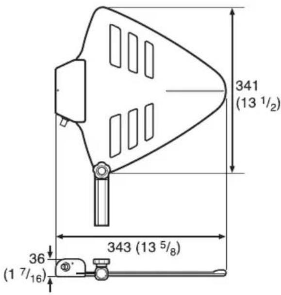
Mass Approx. 530 g (19 oz)
Supplied accessories
Microphone stand attachment pole/grip (1 set)
Stand Adapter
PF1/2 to W5/8 type (1)
PF1/2 to W3/8 type (1)
Operating Instructions (1)
Warranty card (1)
Warranty booklet (1)
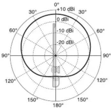
Example of horizontal directivity characteristics
radar
| Angle | Value (dBi) | |-------|-------------| | 0° | +10 | | 30° | 0 | | 60° | -10 | | 90° | -20 | | 120° | -10 | | 150° | -20 | | 180° | -10 |Design and specifications are subject to change without notice.
Note
Always verify that the unit is operating properly before use. SONY WILL NOT BE LIABLE FOR DAMAGES OF ANY KIND INCLUDING, BUT NOT LIMITED TO, COMPENSATION OR REIMBURSEMENT ON ACCOUNT OF THE LOSS OF PRESENT OR PROSPECTIVE PROFITS DUE TO FAILURE OF THIS UNIT, EITHER DURING THE WARRANTY PERIOD OR AFTER EXPIRATION OF THE WARRANTY, OR FOR ANY OTHER REASON WHATSOEVER.
Français
• Frequenze operative: Banda 600 MHz