
RM-NS1000 - Remote control SONY - Free user manual and instructions
Find the device manual for free RM-NS1000 SONY in PDF.

| Product type | System controller for surveillance |
| Brand | Sony |
| Model | RM-NS1000 |
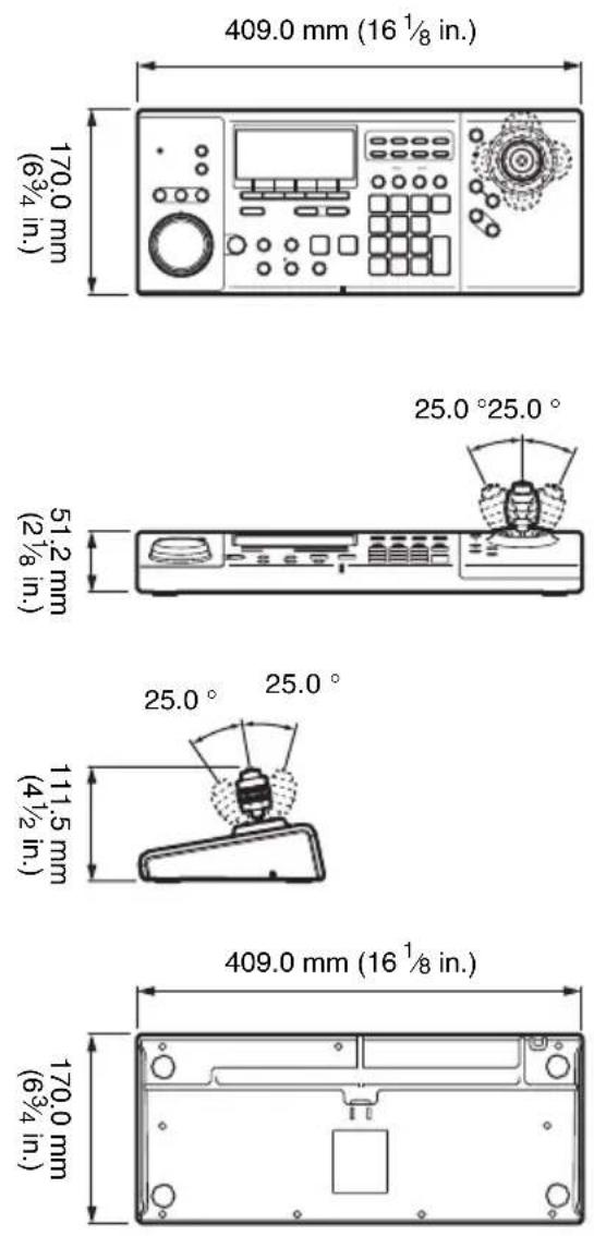
| Dimensions (W x H x D) | 409 x 111.5 x 170 mm |
| Weight | Approx. 1.2 kg |
| Power supply | 12 V DC, AC adapter 100-240 V, 50/60 Hz, max. current consumption 1.0 A |
| Interfaces | USB 2.0 (x2), microphone jack (x1), headphone jack (x1), RS-485 port (x1) |
| Operating modes | RM-NS1000 mode (for NSR-1000 series and RealShot Manager Advanced) and Pelco mode (for Pelco D or P protocol cameras) |
| Supported systems | NSR-1000 series server (v1.1+) and computer with RealShot Manager Advanced (v1.1+) |
| Supplied accessories | AC adapter, Getting Started Guide, CD-ROM (User's Guide), warranty booklet |
| Operating conditions | Temperature: 5 °C to 40 °C; humidity: 20% to 80% (non-condensing) |
| Safety | Do not expose to rain or moisture. No power switch; unplug the power cord if a problem occurs. |
| Maintenance and cleaning | Clean with a soft, dry cloth. Do not use liquids or solvents. |
| Repairability | Refer servicing to qualified personnel. For CD-ROM replacement, contact a Sony service technician. |
| Country of manufacture | Manufactured by Sony Corporation, Japan |
| Certifications | Complies with Canadian NMB-003 (Class B) |
Frequently Asked Questions - RM-NS1000 SONY
User questions about RM-NS1000 SONY
0 question about this device. Answer the ones you know or ask your own.
Ask a new question about this device
Download the instructions for your Remote control in PDF format for free! Find your manual RM-NS1000 - SONY and take your electronic device back in hand. On this page are published all the documents necessary for the use of your device. RM-NS1000 by SONY.
USER MANUAL RM-NS1000 SONY
© 2009 Sony Corporation
WARNING
To reduce the risk of fire or electric shock, do not expose this apparatus to rain or moisture.
To avoid electrical shock, do not open the cabinet. Refer servicing to qualified personnel only.
WARNING
This unit has no power switch.
When installing the unit, incorporate a readily accessible disconnect device in the fixed wiring, or connect the power plug to an easily accessible socket-outlet near the unit. If a fault should occur during operation of the unit, operate the disconnect device to switch the power supply off, or disconnect the power plug.
WARNING
- Use the approved Power Cord (2-core mains lead)/Appliance Connector/Plug that conforms to the safety regulations of each country if applicable.
- Use the Power Cord (2-core mains lead)/Appliance Connector/Plug conforming to the proper ratings (Voltage, Ampere).
If you have questions on the use of the above Power Cord/Appliance Connector/Plug, please consult a qualified service personnel.
IMPORTANT
The nameplate is located on the bottom.
For the customers in the U.S.A.
This equipment has been tested and found to comply with the limits for a Class B digital device, pursuant to Part 15 of the FCC Rules. These limits are designed to provide reasonable protection against harmful interference in a residential installation. This equipment generates, uses, and can radiate radio frequency energy and, if not installed and used in accordance with the instructions, may cause harmful interference to radio communications. However, there is no guarantee that interference will not occur in a particular installation. If this equipment does cause harmful interference to radio or television reception, which can be determined by turning the equipment off and on, the user is encouraged to try to correct the interference by one or more of the following measures:
- Reorient or relocate the receiving antenna.
- Increase the separation between the equipment and receiver.
- Connect the equipment into an outlet on a circuit different from that to which the receiver is connected.
- Consult the dealer or an experienced radio/TV technician for help.
You are cautioned that any changes or modifications not expressly approved in this manual could void your authority to operate this equipment.
Declaration of Conformity
Trade Name :SONY
Model :RM-NS1000
Responsible party
:Sony Electronics Inc.
Address :16530 Via Esprillo, San
Diego, CA 92127 U.S.A.
Telephone Number
:858-942-2230
This device complies with part 15 of the FCC Rules. Operation is subject to the following two conditions: (1) this device may not cause harmful interference, and (2) this device must accept any interference received, including interference that may cause undesired operation.
If you have any questions about this product, you may call;
Sony Customer Information Service Center
1-800-222-7669 or http://www.sony.com/
For the customers in Canada
This Class B digital apparatus complies with Canadian ICES-003.
For the customers in Europe
The manufacturer of this product is Sony Corporation, 1-7-1 Konan, Minato-ku, Tokyo, Japan.
The Authorized Representative for EMC and product safety is Sony Deutschland GmbH, Hedelfinger Strasse 61, 70327 Stuttgart, Germany. For any service or guarantee matters please refer to the addresses given in separate service or guarantee documents.
Usage Notes
About the LCD Display
The LCD panel fitted to this unit is manufactured with high precision technology, giving a functioning pixel ratio of at least 99.99%. Thus a very small proportion of pixels may be “stuck,” either always off (black), always on (red, green, or blue), or flashing. In addition, over a long period of use, because of the physical characteristics of the liquid crystal display, such “stuck” pixels may appear spontaneously. These problems are not a malfunction.
Table of Contents
Usage Notes 3
Function Overview 5
Package Contents 7
Supported Systems 7
Using the CD-ROM Manual ...... 8
Preparations 8
Reading the CD-ROM
Manual 8
Step 1 Connecting Devices ...... 9
Preparing the Devices to Use ... 9
Connecting the USB Cable ..... 9
Connecting the Devices ...... 11
Connecting a Pelco-D or -P
Protocol Camera
(for Use in Pelco Mode) ...... 12
Connecting the AC Adapter ... 13
Step 2 Turning On the Power and
Logging On to the System ...... 14
During Connection to the
NSR-1000 Series or RealShot
Manager Advanced 14
I/O Port 16
Specifications 17
Dimensions 18
Trademarks
- “IPELA” and are
trademarks of Sony Corporation.
Other products or system names appearing in this document are trademarks or registered trademarks of their respective owners.
Further, the ® or ™ symbols are not used in the text.
Function Overview
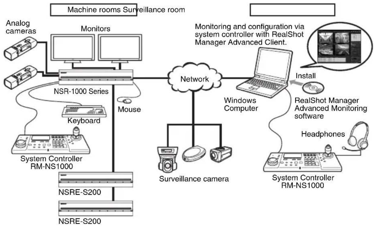
The RM-NS1000 System Controller is a system controller for remotely operating various functions of a surveillance system. Connect it to the surveillance server or the computer used for remote operations in order to perform operations such as monitoring or searching for and playing back recorded images.
The system controller has RM-NS1000 mode, and Pelco mode to select from in accordance with your surveillance server, software, and cameras.
Configuration example in RM-NS1000 mode:
When using the NSR-1000 series or RealShot Manager Advanced, perform operation in RM-NS1000 mode.
flowchart
graph TD
    A["Machine rooms Surveillance room"] --> B["Analog cameras"]
    A --> C["Monitors"]
    A --> D["NSR-1000 Series"]
    D --> E["Mouse"]
    D --> F["Keyboard"]
    D --> G["System Controller RM-NS1000"]
    D --> H["NSRE-S200"]
    D --> I["NSRE-S200"]
    J["Monitoring and configuration via system controller with RealShot Manager Advanced Client."] --> K["Network"]
    K --> L["Surveillance camera"]
    K --> M["Windows Computer"]
    L --> N["Install"]
    M --> O["RealShot Manager Advanced Monitoring software"]
    M --> P["Headphones"]
    O --> Q["System Controller RM-NS1000"]
Note
A keyboard and mouse are required when logging on to the NSR-1000 series or RealShot Manager Advanced.
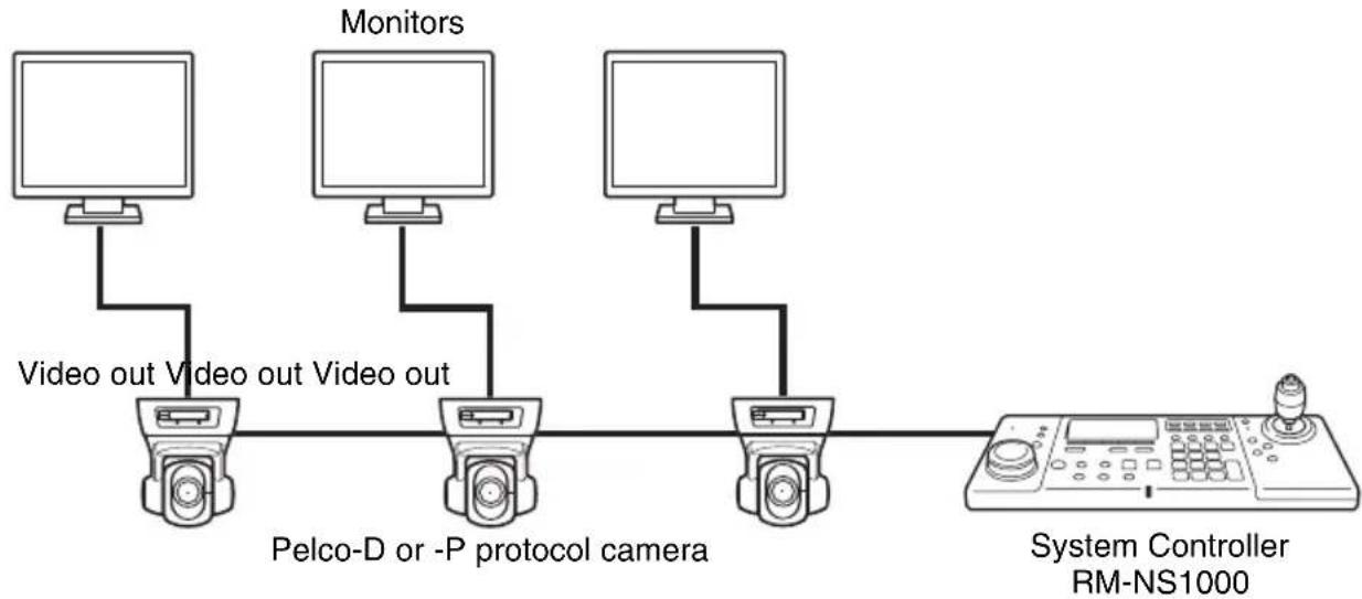
Configuration example in Pelco mode:
When connecting a Pelco-D or -P protocol camera directly to the system controller via the RS-485 port to perform pan, tilt, and zoom control, perform operation in Pelco mode.
flowchart
graph LR
    A["Monitor"] -->|Video out Video out Video out| B["Pelco-D or -P protocol camera"]
    C["Monitor"] -->|Video out Video out Video out| B
    D["System Controller RM-NS1000"] -->|Feedback| B
Package Contents
Check that the following items are included in this package:
• RM-NS1000 System Controller (1)
- AC adapter (1)
natural_image
Line drawing of a control panel with buttons and a dial (no text or symbols visible)
natural_image
Line drawing of a rectangular electronic device with a cable and connector, no text or symbols present- First Step Guide (this document) (1)
• CD-ROM (User's Guide) (1) - Warranty booklet (1)
Notes
- This package may contain additional hardware and/or documentation for those options.
- Save the boxes and packing materials for future use.
Supported Systems
The system controller supports the following systems.
- Sony NSR-1000 Series Network Surveillance Server (Version 1.1 or later)
- A computer on which RealShot Manager Advanced (Version 1.1 or later), an application software with controls compatible with this equipment, is installed
Using the CD-ROM Manual
The supplied CD-ROM includes manuals for this system controller (Japanese, English, French, German, Italian, Spanish and Simplified Chinese versions). The copies of these manuals are created in pdf (Portable Document Format).
Preparations
One of the following programs must be installed on your computer in order to use the operation manuals contained on the CD-ROM disc.
- Adobe Reader Version 6.0 or higher
Note
If Adobe Reader is not installed, you can download it from the following URL: http://www.adobe.com/
Adobe and Adobe Reader are trademarks of Adobe Systems Incorporated in the United States and/or other countries.
Reading the CD-ROM Manual
To read the manual on the CD-ROM, proceed as follows.
1 Insert the CD-ROM disc in your CD-ROM drive. The manuals are saved in the Manual folder.
2 Select and click the manual that you want to read.
Note
Depending on the version of Adobe Reader you are using, the file may not display properly. If the file does not display properly, download the latest version of Adobe Reader from the URL found in the “Preparations” section.
Caution
If you lose the CD-ROM disc or you cannot read it for some reason, you can purchase a new CD-ROM disc. Contact your nearest Sony service representative.
Step 1 Connecting Devices
Decide where to install the system controller and then connect the devices to be used to the controller.
Preparing the Devices to Use
Prepare the devices to be connected to and used with the system controller according to the application.
- USB keyboard
- USB mouse
• Headphones (can only be used with RealShot Manager Advanced) - Microphone (can only be used with RealShot Manager Advanced)
- Pelco-D or -P protocol camera (for use in Pelco mode)
Note
A keyboard and mouse are required when logging on to the NSR-1000 series or RealShot Manager Advanced.
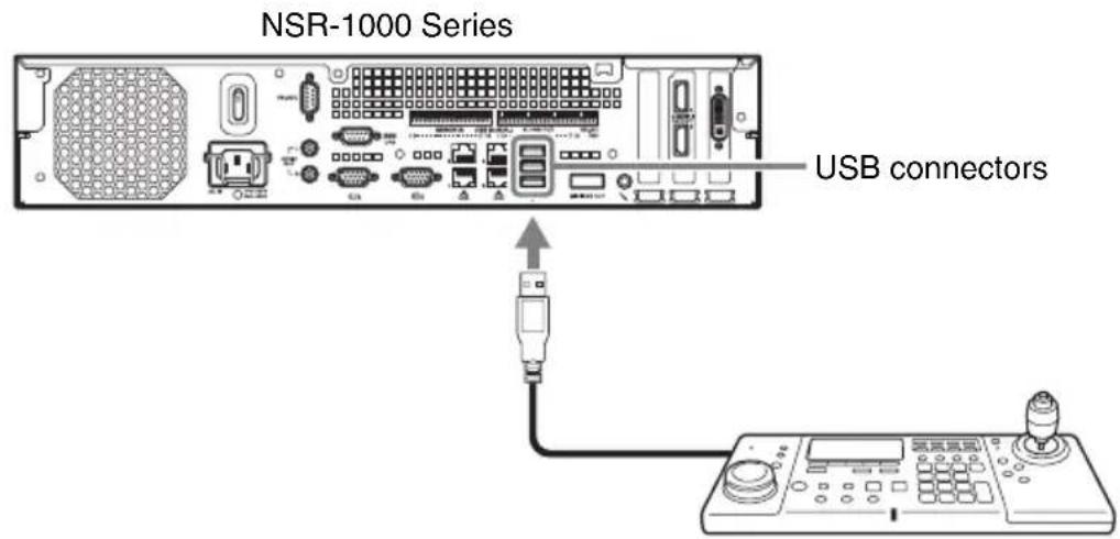
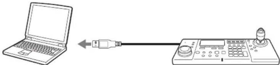
Connecting the USB Cable
Use the USB cable to connect the system controller to the computer on which NSR-1000 series or RealShot Manager Advanced is installed.
1 Thread the USB cable through the groove underneath the controller in accordance with the location that the system controller is placed.
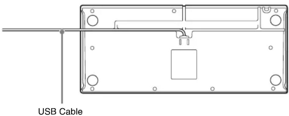
2 Connect the USB cable to the computer on which NSR-1000 series or RealShot Manager Advanced is installed.
or
natural_image
Line drawing showing a laptop connected to a control panel via USB cable (no text or symbols)Windows PC on which RealShot Manager Advanced installed
Connecting the Devices
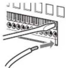
Connect the USB keyboard, USB mouse, microphone, and headphones to the corresponding connectors on the left side of the system controller.

flowchart
graph TD
    A["Keyboard"] --> B["Microphone"]
    A --> C["Headphones"]
    A --> D["Mouse"]
    B --> E["Microphone"]
    C --> F["Headphones"]
    D --> G["Mouse"]
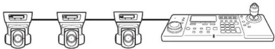
Connecting a Pelco-D or -P Protocol Camera (for Use in Pelco Mode)
Directly connect the analog camera to the RS-485 port on the rear of the system controller. For the connection procedure, see “I/O Port” (page 16).
Caution
Do not connect any device to the USB cable.
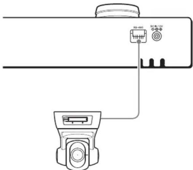
Pelco-D or -P protocol camera
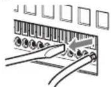
If you want to connect multiple Pelco-D or -P protocol cameras, connect them in parallel as shown in the figure below.
Connecting the AC Adapter
1 Connect the supplied AC adapter and power cord.
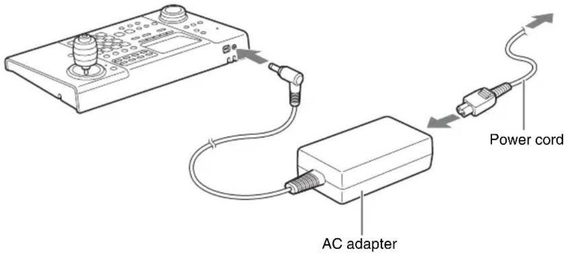
2 Wrap the AC adapter cord around the AC cord holder at the rear of the controller to secure the cord.
Securing the AC adapter cord around the holder prevents the cord from being disconnected.
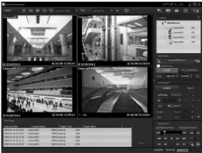
Step 2 Turning On the Power and Logging On to the System
The system controller turns on when the power cord of the AC adapter is plugged into a power outlet.
Note
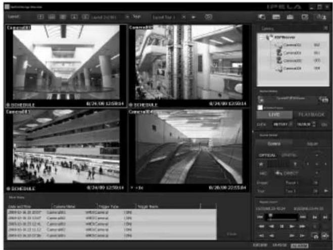
In this chapter, mainly the screens of RealShot Manager Advanced are used for the explanations. These screens are subject to change without notice.
During Connection to the NSR-1000 Series or RealShot Manager Advanced
Note
A keyboard and mouse are required when logging on to the NSR-1000 series or RealShot Manager Advanced. If the user name and password consist only of numbers, you can use the numeric keypad of the system controller to log on.
1 Connect the AC adapter of the system controller to an outlet.
The power of the system controller turns on and the top screen appears.
2 Log on to the system.
Use the keyboard to enter your user name and password, and click [Logon].
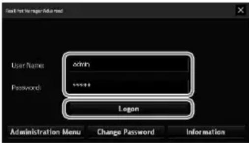
If authentication is successful, the Main screen appears.
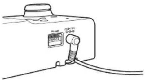
I/O Port
Pin arrangement of I/O port
RS-485
| Pin No. | RS-485 |
| 1 | TX+ |
| 2 | TX- |
| 3 | RX+ |
| 4 | RX- |
| 5 | GND |
- From left to right
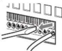
Connection procedure for the I/O port
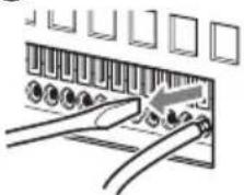
Connect the wires to the R-485 port as described below.
Insert a flat-blade screwdriver into the slot at the top or bottom of the hole to which you want to connect a wire (AWG No. 26 to 20), insert the wire, and then withdraw the flat-blade screwdriver from the slot.
Caution
Do not use excessive force when inserting the flat-blade screwdriver. Doing so may result in a malfunction.
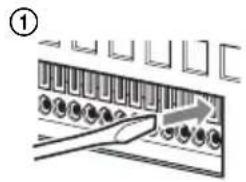
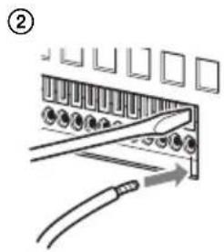
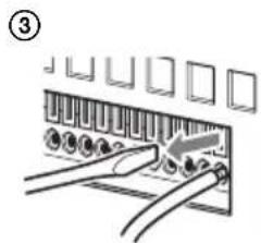
Use the same procedure to connect all of the necessary wires.
Specifications
General
Interface: USB 2.0 low-speed device
External connectors
USB: USB 2.0 (×2)
Microphone jack (×1)
Headphone jack (×1)
RS-485 port (×1)
Operating environment
Operating temperature:
$$ 5 ^ {\circ} \mathrm{C} \text {to} 4 0 ^ {\circ} \mathrm{C} (4 1 ^ {\circ} \mathrm{F} \text {to} 1 0 4 ^ {\circ} \mathrm{F}) $$
Operating humidity:
20% to 80% (max. wet bulb temperature: 32 °C (90 °F)) (no condensation)
Power and miscellaneous
Power: 12 V DC
Power consumption:
Max. 1.0 A
AC adapter:
$$ 1 0 0 - 2 4 0 \mathrm{VAC}, 5 0 / 6 0 \mathrm{Hz} $$
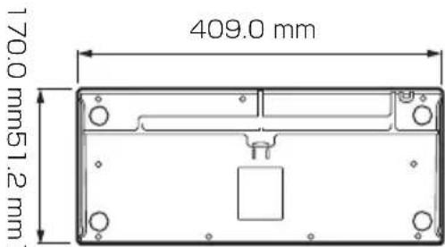
Dimensions:
$$ 4 0 9. 0 (\mathrm{W}) \times 1 1 1. 5 (\mathrm{H}) \times 1 7 0. 0 (\mathrm{D}) \mathrm{mm} $$
$$ (1 6 ^ {1} / _ {8} (\mathrm{W}) \times 4 ^ {1} / _ {2} (\mathrm{H}) \times 6 ^ {3} / _ {4} (\mathrm{D}) \text {in.}) $$
Weight: Approx. 1,200 g (2.6 lb.)
Accessories
AC adapter (×1)
First Step Guide (this document) (×1)
CD-ROM (User's Guide) (×1)
Warranty booklet (×1)
Design and specifications are subject to change without notice.
Note
Always verify that the unit is operating properly before use. SONY WILL NOT BE LIABLE FOR DAMAGES OF ANY KIND INCLUDING, BUT NOT LIMITED TO, COMPENSATION OR REIMBURSEMENT ON ACCOUNT OF THE LOSS OF PRESENT OR PROSPECTIVE PROFITS DUE TO FAILURE OF THIS UNIT, EITHER DURING THE WARRANTY PERIOD OR AFTER EXPIRATION OF THE WARRANTY, OR FOR ANY OTHER REASON WHATSOEVER.
Dimensions
安全のために
natural_image
Line drawing of a control panel with digital display, keyboard, and cylindrical device (no text or symbols)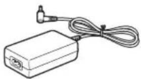
natural_image
Line drawing of a rectangular electronic device with a coiled cable and connector (no text or symbols)
natural_image
Line drawing of a laptop connected to a control panel via a USB cable (no text or symbols present)natural_image
Line drawing of a four-position industrial control device connected in series with a terminal (no text or symbols)AC アダプターを接続する
natural_image
Diagram of a cable connector with a cable inserted into a socket (no text or symbols)③
natural_image
Diagram of a connector or socket assembly with wires and connectors (no text or symbols visible)USB 2.0 Low-speed device
外部コネクター
USB : USB 2.0 (2)
マイク入力 (1)
ヘッドホン端子 (1)
RS-485 端子 (1)
使用環境
動作溫度:5 ℃ \~ 40 ℃
natural_image
Diagram of a device with labeled ports and a central mechanical component (no text or symbols)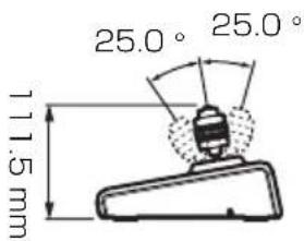
natural_image
Line drawing of a handheld industrial control panel with buttons and a rotary knob (no text or symbols visible)
natural_image
Line drawing of a rectangular electronic device with a cable and connector, no text or symbols presentnatural_image
Technical line drawing of a rectangular electronic device with mounting holes and internal components (no text or symbols)Câble USB
natural_image
Line drawing showing a laptop connected to a control panel via USB cable (no text or symbols)flowchart
graph LR
    A["Control Unit 1"] --> B["Control Unit 2"]
    B --> C["Control Unit 3"]
    C --> D["Control Unit 4"]
Port E/S
natural_image
Illustration of a control panel with buttons and a dial, no visible text or symbols
natural_image
Line drawing of a rectangular electronic device with a coiled cable and connector (no text or symbols)natural_image
Technical line drawing of a rectangular electronic device with mounting holes and a central component (no text or symbols)USB-Kabel
natural_image
Line drawing showing a laptop connected to a control panel via USB cable (no text or symbols)Windows-Computer enthaltene RealShot Manager Advanced
E/A-Anschluss

natural_image
Diagram of a cable inserted into a rack-mounted connector (no text or symbols visible)
The LCD panel fitted to this unit is manufactured with high precision technology, giving a functioning pixel ratio of at least 99.99%. Thus a very small proportion of pixels may be “stuck,” either always off (black), always on (red, green, or blue), or flashing. In addition, over a long period of use, because of the physical characteristics of the liquid crystal display, such “stuck” pixels may appear spontaneously. These problems are not a malfunction.
Indice
Note sull'utilizzo
dell'apparecchio 74
natural_image
Illustration of a control panel with buttons and a dial, no visible text or symbols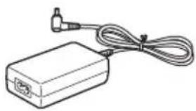
natural_image
Line drawing of a rectangular electronic device with a coiled cable and connector (no text or symbols)natural_image
Technical line drawing of a rectangular electronic device with mounting holes and a central component (no text or symbols)Cavo USB
natural_image
Line drawing showing a laptop connected to a control panel via USB cable (no text or symbols)natural_image
Line drawing of a four-position industrial control device connected in series with a terminal (no text or symbols visible)Porta di I/O
natural_image
Illustration of a control panel with buttons and a dial, no visible text or symbols
natural_image
Line drawing of a rectangular electronic device with a coiled cable and connector (no text or symbols)natural_image
Technical line drawing of a rectangular electronic device with mounting holes and a central component (no text or symbols)Cable USB
0

natural_image
Line drawing showing a laptop connected to a control panel via USB cable (no text or symbols)Puerto de E/S
②
natural_image
Diagram of a cable connector with connectors and a cable, showing no text or symbols③
natural_image
Diagram of a connector with multiple ports and cables, no text or symbols presentnatural_image
Line drawing of a handheld electronic device with control panel and indicator lights (no text or symbols)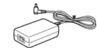
natural_image
Line drawing of a rectangular electronic device with a cable and connector (no text or symbols)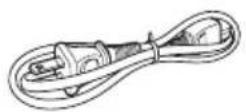
Pelco-D 协议或 Pelco-P 协议摄像头
natural_image
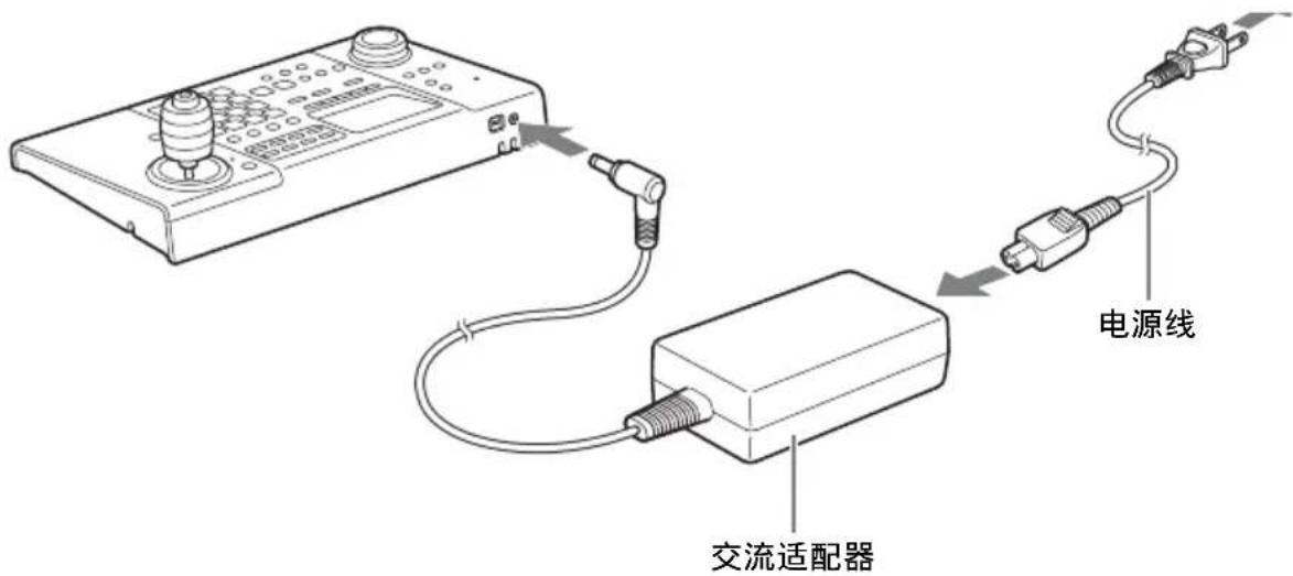
Line drawing of a four-position audio workstation with control panel and speaker (no text or symbols)连接交流适配器
1 连接 AC 适配器和电源线。
如果验证成功,会出现主屏幕。
I/O 端口
I/O 端口引脚布置
RS-485
| 引脚号 | RS-485 |
| 1 | TX+ |
| 2 | TX- |
| 3 | RX+ |
| 4 | RX- |
| 5 | GND |
·从左至右
I/O 端口的连接步骤
natural_image
Diagram of a cable connector with multiple ports and an arrow indicating direction (no text or symbols)③
natural_image
Diagram of a cable connector with connectors and ports, no text or symbols present可使用相同步骤连接所有必要电线。
规格
常规
接口:USB 2.0 低速设备
外部接口
USB: USB 2.0 (×2)
麦克风插孔 (×1)
耳机插孔 (×1)
RS-485 端口 (×1)
工作环境
工作温度: