TE-BJ 900 - Router EINHELL - Free user manual and instructions
Find the device manual for free TE-BJ 900 EINHELL in PDF.

User questions about TE-BJ 900 EINHELL
0 question about this device. Answer the ones you know or ask your own.
Ask a new question about this device
Download the instructions for your Router in PDF format for free! Find your manual TE-BJ 900 - EINHELL and take your electronic device back in hand. On this page are published all the documents necessary for the use of your device. TE-BJ 900 by EINHELL.
USER MANUAL TE-BJ 900 EINHELL
GB Original operating instructions Biscuit jointer
natural_image
Close-up of a handheld electric shaver with labeled parts (no text or symbols visible)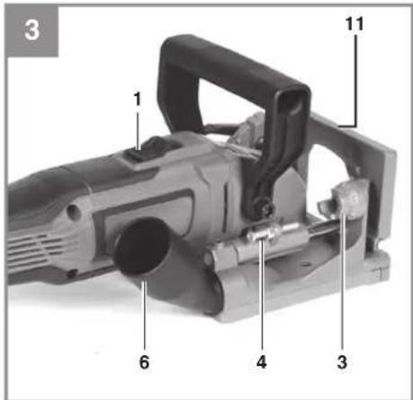
-2-
natural_image
Close-up of a wooden surface with a vertical seam and a shaded rectangular section, no text or symbols visible.
-4-
D
Gefahr!
When using the equipment, a few safety precautions must be observed to avoid injuries and damage. Please read the complete operating instructions and safety regulations with due care. Keep this manual in a safe place, so that the information is available at all times. If you give the equipment to any other person, hand over these operating instructions and safety regulations as well. We cannot accept any liability for damage or accidents which arise due to a failure to follow these instructions and the safety instructions.
Explanation of the symbols used (see Fig. 14)
- Danger! - Read the operating instructions to reduce the risk of injury.
- Caution! Wear ear-muffs. The impact of noise can cause damage to hearing.
- Caution! Wear a breathing mask. Dust which is injurious to health can be generated when working on wood and other materials. Never use the device to work on any materials containing asbestos!
- Caution! Wear safety goggles. Sparks generated during working or splinters, chips and dust emitted by the device can cause loss of sight.
1. Safety regulations
The corresponding safety information can be found in the enclosed booklet.
Warning!
Read all the safety information, instructions, illustrations and technical data provided on or with this power tool. Failure to adhere to the following instructions may result in electric shock, fi re and/or serious injury.
Keep all the safety information and instructions in a safe place for future use.
2. Layout and items supplied
2.1 Layout
- On/Off switch
- Locking lever for angle adjustment
- Stop for adjustment of the cutting depth
- Adjustment screw for cutting depth
- Additional handle
- Adapter for dust bag
- Dust bag
- Face spanner
9. Spindle lock
- Cover plate
- Angle stop
- Handle
- Spacer plate
- Height-adjustable stop
- Locking lever for height-adjustable stop
- Height adjustment wheel for height-adjustable stop
- Hexagon key
- Socket head screw
- Rubber tips
- Cutter
- Flange
- Height scale
- Base plate
2.2 Items supplied
Please check that the article is complete as specified in the scope of delivery. If parts are missing, please contact our service center or the sales outlet where you made your purchase at the latest within 5 working days after purchasing the product and upon presentation of a valid bill of purchase. Also, refer to the warranty table in the service information at the end of the operating instructions.
- Open the packaging and take out the equipment with care.
- Remove the packaging material and any packaging and/or transportation braces (if available).
- Check to see if all items are supplied.
- Inspect the equipment and accessories for transport damage.
- If possible, please keep the packaging until the end of the guarantee period.
Danger!
The equipment and packaging material are not toys. Do not let children play with plastic bags, foils or small parts. There is a danger of swallowing or suff ocating!
- Biscuit jointer
- Dust bag
Face spanner - Hexagon key
• Height-adjustable stop - Spacer plate
Rubber tips
• Original operating instructions - Safetyinstructions
GB
3. Proper use
The biscuit jointer is designed for cutting slots for biscuit joints in solid wood, plywood and partic- leboard.
The equipment is to be used only for its prescribed purpose. Any other use is deemed to be a case of misuse. The user / operator and not the manufacturer will be liable for any damage or injuries of any kind caused as a result of this.
Please note that our equipment has not been designed for use in commercial, trade or industrial applications. Our warranty will be voided if the machine is used in commercial, trade or industrial businesses or for equivalent purposes.
4. Technical data
Voltage: 220-240 V\~50 Hz
Power rating: 900 watts
ldling speed: 11,000 rpm
Cutter dimensions:....ø 100 x ø 22 x 4.0 mm
Cutting depth: max. 20 mm
Angle settings: 0°-90°
Protection class:
Weight: 2.65 kg
Danger!
Sound and vibration
Sound and vibration values were measured in accordance with EN 60745.
L_dA sound pressure level 87 dB(A)
K_ A uncertainty 3 dB
L_WA sound power level 98 dB(A)
K_WA uncertainty 3 dB
Wear ear-muff s.
The impact of noise can cause damage to hearing.
Total vibration values (vector sum of three directions) determined in accordance with EN 60745.
Vibration emission value a_b ≤ 2.5 m/s^2
K uncertainty = 1.5 m/s²
The specified vibration emission value was established in accordance with a standardized testing method. It can change depending on how the electric equipment is used and may exceed the specified value in exceptional circumstances.
The specified vibration emission value can be used to compare the equipment with another electric power tools.
The specified vibration emission value can be used for initial assessment of any potential negative impact.
Keep the amount of noise generated and the vibrations to a minimum.
- Only use equipment that is in perfect working order.
- Maintain and clean the equipment regularly.
• Adapt your way of working to the equipment. - Do not overload the equipment.
• Have the equipment checked if necessary. - Switch off the equipment when it is not in use.
Caution!
Residual risks
Even if you use this electric power tool in accordance with instructions, certain residual risks cannot be rules out. The following hazards may arise in connection with the equipment's construction and layout:
- Lung damage if no suitable protective dust mask is used.
- Damage to hearing if no suitable ear protection is used.
- Health damage caused by hand-arm vibrations if the equipment is used over a prolonged period or is not properly guided and maintained.
5. Before starting the equipment
Before you connect the equipment to the mains supply make sure that the data on the rating plate are identical to the mains data.
Warning!
Always pull the power plug before making adjustments to the equipment.
5.1 Dust bag assembly (Fig: 1-2)
- The dust bag (7) is mounted by pushing it onto the dust bag adapter (6).
• It can be rotated by the user into any position
GB
in order to make the work comfortable.
- If the dust bag (7) is full or you have finished your work, then it can be taken off again and emptied by opening the zip fastener.
- It is also possible to connect a dust extractor (vacuum cleaner) to the dust bag adapter (6) (Fig. 2).
5.2 Adjusting the cutting depth (Fig. 3)
- A total of 6 different cutting depths can be selected.
- To do this, use the stop (3) to set the required cutting depth.
- The designations on the stop (3) indicate the various sizes of biscuit.
- The adjustment screw (4) can be used to re-adjust the cutting depth adjustment.
| Size at stop | 0 | 1 | 0 | 2 | 0 | BAX^* | |
| Biscuit size | 0 | 1 | 0 | 2 | 0 | - | |
| Slot depth | 8 mm | 10 mm | 12,3 mm | 13 mm | 14,7 mm | 20 mm | |
*without rubber tips
Warning!
Prior to use, check that the guard hood return mechanism works properly.
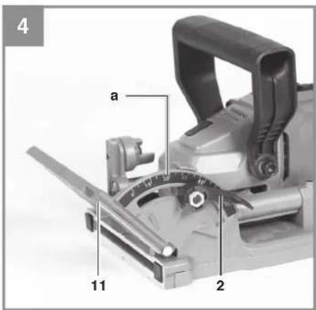
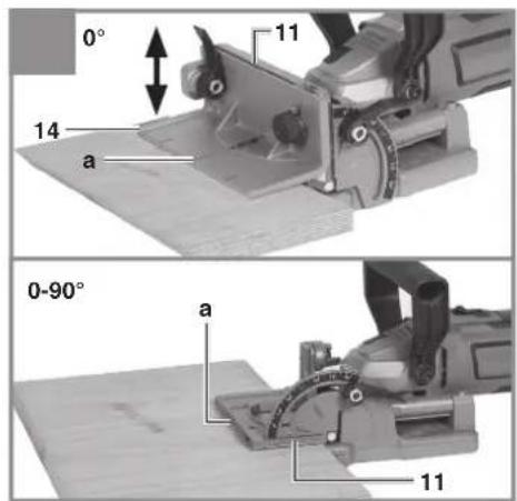
5.3 Adjustment of the cutting angle (Figs. 4 + 5 / item 11)
For slots on inclined surfaces, e.g. for miter joints, the angle of the stop (11) can be adjusted accordingly.
- Undo the locking lever for angle adjustment (2).
- Caution! The angle is indicated by the marking (a).
- You can freely adjust the angle stop (11) to any required angle between 0^ and 90^ .
- Then retighten the locking lever for angle adjustment (2).
Note:
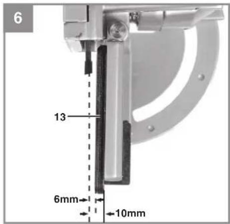
If the angle stop (11) is set to an angle of 90^ then the height between the middle of the cutter and the angle stop (11) without the spacer plate (13) or height adjustment (14) is always 10mm (see Fig. 6).
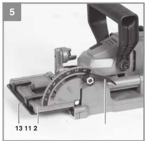
5.4 Spacer plate (Figs. 5-6 / item 13)
The spacer plate (13) also allows thin workpieces to be cut. If the angle stop (11) is set to an angle of 90^ then the height between the middle of the cutter and the angle stop (11) is always 6 mm. See Fig. 6.
To do this, mount the spacer plate (13) on the angle stop (11) as shown in Fig. 5.
Note: The spacer plate (13) can also be used on miter joints in order to ensure that the slot is not cut too deep.
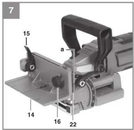
5.5 Height adjustment (Fig. 7 / item 14)
With the height-adjustable stop (14) it is also possible to work on thinner workpieces. The height between the middle of the cutter and the height-adjustable stop (14) can be adjusted between 0 mm and 40 mm.
- Undo the locking lever for the height-adjustable stop (15).
- Then insert the height-adjustable stop (14) as shown in Fig. 7.
- Adjust the required height on the height scale (22) by means of the adjustment screw (16). The arrow (a) indicates the set height.
Note: The height of the slot should always be in the middle of the workpiece.
- Then retighten the locking lever for the height-adjustable stop (15) again.
Caution! The height-adjustable stop (14) must only be used with a cutting angle of 0^ .
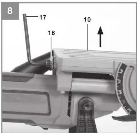
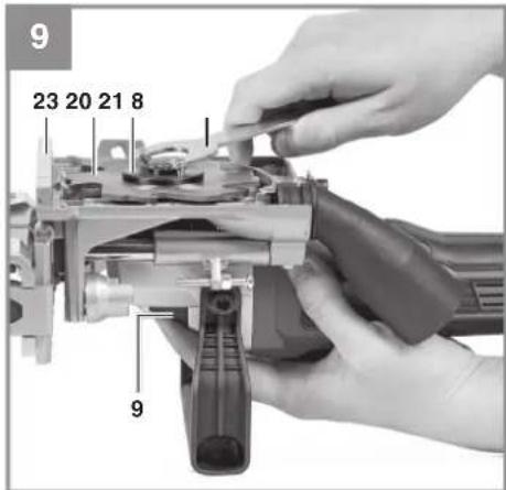
5.6 Changing the cutter (Figs. 8-9)
Danger! The plug must be disconnected from the mains supply.
Remove the cover plate (10) by slightly loosening the socket head screw and then take off the cover plate (10).
- Place the face spanner (8) on the flange (21).
- Press the spindle lock (9); hold it pressed and turn the face spanner in the direction of rotation. After approximately half a turn the spindle lock (9) will engage and the flange (21) can be released.
• Then release the cutter (20) from the housing. - As the next step, pull the cutter (20) out of the base plate (23).
- Then insert the new cutter (20), following the above instructions in reverse. Check that the direction of rotation of the cutter is correct.
• Secure the cover plate (10) again.
GB
Danger: Never press the spindle lock (9) while the motor is running. Check that the cutter is stationary and securely seated before starting work.
Note: Do not use blunt or damaged disk cutters.
6. Operation
6.1 On/Off switch (Fig. 3; item 1)
To start the unit, slide the On/Off switch (1) forward and press it down. To switch off the biscuit jointer, depress the On/Off switch (1) at the back. The On/Off switch (1) will jump back into its starting position.
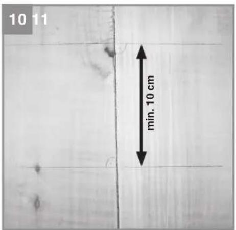
6.2 Marking a workpiece (Fig. 10)
Before you start working with the biscuit jointer, the workpiece must be marked as follows:
- Place the two parts side by side; the workpieces must be securely clamped.
- Draw a line with a pencil at right angles to the joint.
• Multiple joints will be required on longer pieces of wood. - The distance between two lines should be at least 10 cm.
Note:
On thicker workpieces you can create additional stability by cutting two slots one above the other; on thinner workpieces a single joint will be sufficient.
6.3 Positioning the biscuit jointer and cutting slots (Fig. 11)
Cutting slots with an angle of 0^ at a particular height
- Adjust the angle stop (11) to 0^ and then insert the height-adjustable stop (14).
- Adjust the required height with the aid of the height-adjustable stop (14) (see 5.5).
• Position the machine close to the workpiece. - There are markings (a) on the machine; these must line up with the line marked on the workpiece.
- Then switch on the machine and push the handle (12) forward. The workpiece must be securely clamped when doing this.
Cutting slots with an angle between 0° and 90°
- Adjust the required cutting depth and check it (see 5.2).
- Adjust the required cutting angle using the angle stop (11) (see 5.3).
• Position the machine close to the workpiece. - There are markings (a) on the machine; these must line up with the line marked on the workpiece.
- Then switch on the machine and push the handle (12) forward. The workpiece must be securely clamped when doing this.
CAUTION! The height-adjustable stop (14) must only be used with a cutting angle of 0^ .
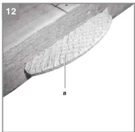
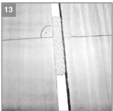
6.4 Connecting the workpieces (Figs. 12-13)
- Once you have cut a slot on both workpieces they can be connected.
• Apply glue in both slots. - Insert the biscuit (a) into one of the slots (Fig. 12).
• Slide both workpieces together (Fig. 13). - Clamp the workpieces and wait until the glue has set.
7. Replacing the power cable
Danger!
If the power cable for this equipment is damaged, it must be replaced by the manufacturer or its after-sales service or similarly trained personnel to avoid danger.
8. Cleaning, maintenance and ordering of spare parts
Danger!
Always pull out the mains power plug before starting any cleaning work.
8.1 Cleaning
- Keep all safety devices, air vents and the motor housing free of dirt and dust as far as possible. Wipe the equipment with a clean cloth or blow it with compressed air at low pressure.
• We recommend that you clean the device immediately each time you have finished using it.
GB
- Clean the equipment regularly with a moist cloth and some soft soap. Do not use cleaning agents or solvents; these could attack the plastic parts of the equipment. Ensure that no water can seep into the device. The ingress of water into an electric tool increases the risk of an electric shock.
8.2 Carbon brushes
In case of excessive sparking, have the carbon brushes checked only by a qualified electrician. Danger! The carbon brushes should not be replaced by anyone but a qualified electrician.
8.3 Maintenance
There are no parts inside the equipment which require additional maintenance.
8.4 Ordering spare parts and accessories
Please provide the following information when ordering spare parts:
- Type of unit
• Article number of the unit
• ID number of the unit - Spare part number of the required spare part For our latest prices and information please go to www.Einhell-Service.com
9. Disposal and recycling
The equipment is supplied in packaging to prevent it from being damaged in transit. The raw materials in this packaging can be reused or recycled. The equipment and its accessories are made of various types of material, such as metal and plastic. Never place defective equipment in your household refuse. The equipment should be taken to a suitable collection center for proper disposal. If you do not know the whereabouts of such a collection point, you should ask in your local council offices.
10. Storage
Store the equipment and accessories in a dark and dry place at above freezing temperature. The ideal storage temperature is between 5 and 30°C. Store the electric tool in its original packaging.
GB
Disposal

Power tools, rechargeable batteries, accessories and packaging should be sorted for environmental-friendly recycling.
Do not dispose of power tools and batteries/rechargeable batteries into household waste!
Only for EU countries:
According to the Directive 2012/19/EU on waste electrical and electronic equipment and its transposition into national law, power tools that are no longer usable, and, according to the Directive 2006/66/EC, defective or drained batteries must be collected separately and disposed of in an environmentally correct manner.
If disposed incorrectly, waste electrical and electronic equipment may have harmful effects on the environment and human health, due to the potential presence of hazardous substances.
Only for United Kingdom:
According to The Waste Electrical and Electronic Equipment Regulations 2013 (SI 2013/3113) (as amended) and the Waste Batteries and Accumulators Regulations 2009 (SI 2009/890) (as amended), products that are no longer usable must be collected separately and disposed of in an environmentally friendly manner.
The reprinting or reproduction by any other means, in whole or in part, of documentation and papers accompanying products is permitted only with the express consent of the Einhell Germany AG.
Subject to technical changes
GB
Service information
We have competent service partners in all countries named on the guarantee certificate whose contact details can also be found on the guarantee certificate. These partners will help you with all service requests such as repairs, spare and wearing part orders or the purchase of consumables.
Please note that the following parts of this product are subject to normal or natural wear and that the following parts are therefore also required for use as consumables.
| Category Example | |
| Wear parts* Carbon brushes | |
| Consumables* Cutter blade | |
| Missing parts |
* Not necessarily included in the scope of delivery!
In the effect of defects or faults, please register the problem on the internet at www.Einhell-Service.com. Please ensure that you provide a precise description of the problem and answer the following questions in all cases:
• Did the equipment work at all or was it defective from the beginning?
• Did you notice anything (symptom or defect) prior to the failure?
• What malfunction does the equipment have in your opinion (main symptom)?
Describe this malfunction.
GB
Warranty certifi cate
Dear Customer,
All of our products undergo strict quality checks to ensure that they reach you in perfect condition. In the unlikely event that this equipment develops a fault, please contact our service department at the address shown on this guarantee card. You can also contact us by telephone using the service number shown. Please note the following terms under which guarantee claims can be made:
-
These guarantee terms apply solely to consumers, i.e. natural persons, who do not want to use this product in connection with either their commercial or other self-employed activities. These guarantee terms regulate additional guarantee services which the undermentioned manufacturer promises to buyers of its new products in addition to their statutory rights of guarantee. Your statutory rights of guarantee are not affected by this guarantee. Our guarantee is free of charge to you.
-
The guarantee services cover only defects due to material or manufacturing faults on the new product which you have bought in the European Union from the undermentioned manufacturer and are limited to either the rectification of said defects or the replacement of the product, whichever we prefer. Please note that only equipment under the brand name "Professional" has been designed for use in commercial, trade or professional applications. For all other products the guarantee is invalidated if the equipment is used within the guarantee period in commercial, trade or industrial applications or for other equivalent activities.
-
Our guarantee does not cover:
-
Damage to the equipment caused by failure to comply with the installation/assembly instructions or by unprofessional installation; damage caused by failure to comply with the operating instructions (e.g. connection to the wrong mains voltage or current type); damage caused by failure to comply with the maintenance and safety regulations; damage caused by exposing the equipment to abnormal environmental conditions; damage resulting from poor care and maintenance.
- Damage to the equipment caused by misuse or incorrect applications (e.g. overloading the equipment or using non-approved attachments or accessories); damage caused by foreign bodies (e.g. sand, stones, dust, ....) getting inside the equipment. Damage in transit; damage caused by force or external influences (e.g. by dropping the equipment).
-
Damage to the equipment or parts of the equipment which is owed to use-related, normal or otherwise natural wear. For example, batteries and battery packs are manufactured with a cycle limit for design-related reasons. Wear is negatively influenced in particular by load demands and charging speeds as well as exposure to heat, cold, vibration and impact.
-
The guarantee is valid for a period of 2 years starting from the purchase date of the equipment. Guarantee claims must be submitted before the end of the guarantee period and within two weeks of the defect being noticed. No guarantee claims will be accepted after the end of the guarantee period. The original guarantee period remains applicable to the equipment even if repairs are carried out or parts are replaced. In such cases, the work performed or parts fitted will not result in an extension of the guarantee period, and no new guarantee will become active for the work performed or for any replacement parts fitted. This also applies if on-site service is used.
-
To assert your guarantee claim, register the defective equipment at: www.Einhell-Service.com. You will need to provide proof of purchase of the new item of equipment. Equipment returned without such proof or without a rating plate are excluded from the guarantee services because of the lack of traceability. If the defect is covered by our guarantee, then either the item in question will be repaired immediately and returned to you or we will send you a new replacement.
-
If you have taken the equipment with you to a different EU country than where you bought it, we will arrange for a local service partner to provide the guarantee services. If you take the equipment outside the EU, the guarantee will not apply.
Of course, we are also happy to offer a chargeable repair service for any defects which are not covered or no longer covered by the scope of this guarantee. To take advantage of this service, please send the equipment to our service address. We draw attention to the restrictions of this guarantee concerning wear parts, consumables and missing parts as presented in the service information included in this operating manual.
Warrantor/ Service:
Einhell UK Ltd, Unit 10, 1st Floor, Champion's Business Park, Arrowe Brook Road, Upton, Wirral, CH49 0UQ
F
Danger!
5.6 Freeswissel (afb. 8 - 9)
Wymiary frezu ....∅ 100 x ∅ 22 x 4,0 mm
Subject to change without notice
Archive-File/Record: NAPR027150
Documents registrar: Christoph Egginger
Wiesenweg 22, D-94405 Landau/Isar
"8" Biscuit jalaner - F Frasuisse à lamèlie - FR Fresnice lamellaire - OK Lamattifosor - SL Lamattifs - CZ Frásica na lamellou spôle - SK Frasza de drazky prochtych čespr. - NL Lamellentres - E Engelindadora - FIN Lamittysin - SL Rozifikamir za pioxo motriončen. - H Lapostilmimo - RO Masina do zrostru pentru cibrat plota - GR Opcapulizadora - P Fresdamor polo meditra - NR Biscil Gedeica tra uradu uskí ultrou RS Gedeica za uradu uskí žicnota - FL Renaria do pokraczni na kolki slasisk. TR Vassá Dubel Frasista - RUSFRZD para lacerasne turçuvsk názos EE Lepistobilisitres - LV Piakano Ispu Irúve - LT Freusa sujogimans - SG Frasza za ratsové, betov - URI instrumenti da fraperzursivanie naste y derivativní OB Kivství globalika - NO Fiatpurgyes - JS Keveli

Declaration of conformity
We, Einhell UK Ltd
Champions Business Park, First Floor Unit 10, Arrowe Brook Rd, Upton, Wirral CH49 0AB, United Kingdom
declare the conformity to UK standards and legislation was assessed for:
Biscuit Jointer TE-BJ 900 (Einhell)
UK legislation
□ Simple Pressure Vessels (Safety) Regulation
□ Electrical Equipment (Safety) Regulation
□ Radio Equipment Regulation
□ Personal Protective Equipment Regulation
☐ The Ecodesign for Energy-Related Products and Energy Information Regulation
X The Restriction of the Use of Certain Hazardous Substances in Electrical and Electronic Equipment Regulation
□ Noise Emission in the Environment by Equipment for use Outdoors Regulation
☒ Electromagnetic Compatibility Regulation
□ Measuring Instruments Regulation
□ Pressure Equipment (Safety) Regulation
Annex V
Annex VI
Noise:measuredL ww = dB (A); guaranteed L ww = dB (A)
P = kW; L/∅ = cm
UK Approved Body:
X Supply of Machinery (Safety) Regulation
□ Annex IV
UK Approved Body:
UKTE Certifi cate No.:
Standards: BS EN 60745-1; BS EN 60745-2-19; BS EN IEC 55014-1; BS EN IEC 55014-2; BS EN IEC 61000-3-2; BS EN 61000-3-3
Wirral, 2023.08.09

Archive-File/Record: NAPR027150
Article Number: 43.506.40 I.-No.: 21012
Subject to change without notice Wiesenweg 22, 94405 Landau/Isar, Germany
Documents registrar: Egginger Christoph
EH 08/2023 (01)