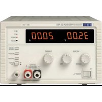
TSX3510 - Power Supply Aim TTi - Free user manual and instructions
Find the device manual for free TSX3510 Aim TTi in PDF.


| Product Type | Laboratory Power Supply |
| Brand | Aim TTi |
| Model | TSX3510 |
| Category | Power Supply |
| Safety Class | Class 1 per EN61010-1 |
| Standards | EN61010-1, Installation Category II, Pollution degree 2 |
| Supply Voltage (a.c.) | 115 V or 230 V selectable |
| Fuse | 10 A 250 V HBC time-delay, 5 × 20 mm |
| Operating Temperature Range | 5 °C to 40 °C, humidity 20-80 % non-condensing |
| Display | Two digital displays (voltage and current) |
| Output Controls | Three rotary controls to set voltage and current limit |
| Overvoltage Protection (OVP) | Adjustable from 10% to 110% of maximum output, set on front panel |
| Thermal Protection | Semiconductor overheating detection |
| Reverse Polarity Protection | Protection diode, max reverse current 3 A |
| Remote Sensing | Sensing terminals at the rear to compensate for voltage drop in wires |
| Series/Parallel Connection | Possible to obtain higher voltages or currents |
| I METER DAMPING Function | Ammeter damping to display average value |
| CHECK V/I Button | Checks the applied voltage and current |
| TRIP Display | Indicates interruption due to overvoltage, overheating, or sensing error |
| Cooling | Natural convection, do not obstruct ventilation |
| Cleaning | Soft cloth slightly damp (water or mild detergent), do not let water enter |
| Repairs | Reserved for qualified personnel, refer to maintenance manual |
Frequently Asked Questions - TSX3510 Aim TTi
User questions about TSX3510 Aim TTi
0 question about this device. Answer the ones you know or ask your own.
Ask a new question about this device
Download the instructions for your Power Supply in PDF format for free! Find your manual TSX3510 - Aim TTi and take your electronic device back in hand. On this page are published all the documents necessary for the use of your device. TSX3510 by Aim TTi.
USER MANUAL TSX3510 Aim TTi
THURLBY THANDAR INSTRUMENTS
TSX Series
High Current DC Power Supplies
INSTRUCTION MANUAL
Aim-TTi
Table of Contents
Introduction 2
Specification 3
Safety 4
Installation 5
Operation 6
Maintenance and Repair 7
Instructions en Francais
Sécurité 8
Installation 9
Fonctionnement 10
This series of bench power supplies offer high power outputs (in excess of 350 Watts) in a casing which is both compact and lightweight when compared with conventional designs. Their high performance is derived from a regulator design which combines switch-mode and linear techniques to achieve high efficiency with excellent regulation, transient response and very low noise.
The supplies feature high accuracy voltage and current metering on bright 0.5" LEDs, overvoltage and thermal protection, and remote sense terminals. The output operates in constant voltage or constant current mode with automatic crossover and mode indication. Coarse and fine controls permit the output voltage to be set within 10mV and the current limit control is logarithmic to give good resolution at low current settings.
The supplies have a robust steel case which is half-rack width (3U height). They are Safety Class I, Installation Category II instruments which meet EN61010-1 safety requirements and comply with EN61326-1 EMC standard.
Specification
OUTPUT SPECIFICATIONS
| Voltage Range: | Nominally 0-35V (35V/10A), Nominally 0-18V (18V/20A) |
| Current Range: | Nominally 0-10A (35V/10A), Nominally 0-20A (18V/20A) |
| Output Voltage Setting: | By coarse and fine controls; 10mV setting resolution. |
| Output Current Setting: | By single semi-logarithmic control; 10mA setting resolution. |
| Output Mode: | Constant voltage or constant current with automatic crossover. |
| Output Switch: | Electronic. Preset voltage and current displayed when off. |
| Output Terminals: | 4mm terminals on front panel, screw terminals at rear. |
| Sensing: | Remote via rear panel screw terminals or direct via shorting strip (supplied). |
| Output Impedance: | <1mΩ in constant voltage mode. >5kΩ in constant current mode (voltage limit at max.). |
| Output Protection: | Forward protection by Over-Voltage-Protection (OVP) trip; maximum voltage that should be applied to the terminals is 50V. Reverse protection by diode clamp for reverse currents up to 3A. |
| OVP Range: 10% to 110% of maximum output voltage set by front panel screwdriver adjustment. | |
OVP Delay: < 200µs
Load & Line Regulation: <0.01% of maximum output for 90% load change or 10% line change.
Ripple & Noise: <1mV rms typical in constant voltage
<3mA rms typical in constant current.
HF Common Mode Typically < 3mV rms, < 10mV peak. Noise:
Transient Response: 20μs to within 50mV of setting for a 5% to 95% load change.
Temperature Coefficient: Typically < 100 ppm / °C
Protection Functions: Overvoltage trip. Regulator overtemperature. Sense miswiring.
Status Indication: Output off lamp. Constant voltage mode lamp Constant current mode lamp. Trip message on display.
METER SPECIFICATIONS
Meter Types: Dual 4 digit meters with 12.5mm (0.5") LEDs. Reading rate 4Hz.
Meter Resolution: 10mV, 10mA
Meter Accuracy: Voltage 0.2% of reading ± 1 digit, current 0.5% of reading ± 1 digit.
GENERAL
AC Input Voltage: 110V-120V AC or 220V-240V AC ± 10%, 50/60Hz. Installation Category II.
Power Consumption: 600VA max.
Operating Range: 5°C to +40°C , 20% to 80% RH.
Storage Range: -40°C to +70°C .
Environmental: Indoor use at altitudes up to 2000m, Pollution Degree 2.
Size: 210 × 140 × 385mm (W x H x D), half rack width x 3U height (optional rack mounting kit available)
Weight: 5kg.
Safety & EMC: Complies with EN61010-1 & EN61326-1. For details, request the EU Declaration of Conformity for this instrument via http://www.aimtti.com/support (serial no. needed).
Safety
This power supply is a Safety Class I instrument according to IEC classification and has been designed to meet the requirements of EN61010-1 (Safety Requirements for Electrical Equipment for Measurement, Control and Laboratory Use). It is an Installation Category II instrument intended for operation from a normal single phase supply.
This instrument has been tested in accordance with EN61010-1 and has been supplied in a safe condition. This instruction manual contains some information and warnings which have to be followed by the user to ensure safe operation and to retain the instrument in a safe condition.
This instrument has been designed for indoor use in a Pollution Degree 2 environment in the temperature range 5°C to 40°C , 20% - 80% RH (non-condensing). It may occasionally be subjected to temperatures between +5°C and -10°C without degradation of its safety. Do not operate while condensation is present.
Use of this instrument in a manner not specified by these instructions may impair the safety protection provided. Do not operate the instrument outside its rated supply voltages or environmental range.
WARNING! THIS INSTRUMENT MUST BE EARTHED
Any interruption of the mains earth conductor inside or outside the instrument will make the instrument dangerous. Intentional interruption is prohibited. The protective action must not be negated by the use of an extension cord without a protective conductor.
When the instrument is connected to its supply, terminals may be live and opening the covers or removal of parts (except those to which access can be gained by hand) is likely to expose live parts. The apparatus shall be disconnected from all voltage sources before it is opened for any adjustment, replacement, maintenance or repair. Capacitors inside the power supply may still be charged even if the power supply has been disconnected from all voltage sources but will be safely discharged about 10 minutes after switching off power.
Any adjustment, maintenance and repair of the opened instrument under voltage shall be avoided as far as possible and, if inevitable, shall be carried out only by a skilled person who is aware of the hazard involved.
If the instrument is clearly defective, has been subject to mechanical damage, excessive moisture or chemical corrosion the safety protection may be impaired and the apparatus should be withdrawn from use and returned for checking and repair.
Make sure that only fuses with the required rated current and of the specified type are used for replacement. The use of makeshift fuses and the short-circuiting of fuse holders is prohibited. Do not wet the instrument when cleaning it.
The following symbols are used on the instrument and in this manual:
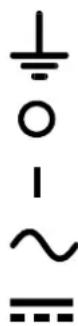
Earth (ground) terminal.
mains supply OFF.
mains supply ON.
alternating current (ac)
direct current (dc)
Mains Operating Voltage
Check that the instrument operating voltage marked on the rear panel is suitable for the local supply. Should it be necessary to change the operating voltage, proceed as follows:
- Ensure that the instrument is disconnected from the AC supply.
- Remove the 6 screws holding the case upper and lift off the cover.
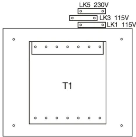
- Change the appropriate zero-ohm links beside the transformer on the pcb:
Link LK5 only for 230V operation
Link LK1 and LK3 only for 115V operation
- Re-assemble in the reverse order.
- To comply with safety standard requirements the operating voltage on the rear panel must be changed to clearly show the new voltage setting.
Mains Lead
When a three core mains lead with bare ends is provided this should be connected as follows:
BROWN - MAINS LIVE
BLUE - MAINS NEUTRAL
When fitting a fused plug a 5 amp fuse should be fitted inside the plug. As the colours of the wires in the mains lead of this apparatus may not correspond with the coloured markings identifying the terminals in your plug proceed as follows:
The wire which is coloured green-and-yellow must be connected to the terminal in the plug which is marked by the letter E or by the safety earth symbol shown above or coloured green or green-and-yellow.
The wire which is coloured blue must be connected to the terminal which is marked with the letter N or coloured black.
The wire which is coloured brown must be connected to the terminal which is marked with the letter L or coloured red.
WARNING! THIS APPARATUS MUST BE EARTHED.
Any interruption of the protective conductor inside or outside the apparatus or disconnection of the protective earth terminal is likely to make the apparatus dangerous. Intentional interruption is prohibited.
Operation
Output Setting
With the POWER switch on (I) and the OUTPUT push-button switch off (out) the output voltage and current limit can be accurately set using the three output controls; the left-hand meter indicates set voltage and the right-hand meter set current.
When the OUTPUT is switched on, the ON LED and the CV (constant voltage) LED will light; the left-hand meter continues to show the set voltage but the right-hand meter now shows actual current drawn. Alternate presses of the I METER DAMPING button will switch current meter damping in and out; with damping switched in the DAMPED LED will be lit and the average value of a varying load current will be read.
If the output goes into current limit the CI (constant current) LED will light instead of the CV LED and the left-hand meter will now show the actual voltage at the output terminals; the right-hand meter will continue to show the set current limit.
At any time, the set voltage and set current levels can be reviewed by pressing the CHECK V/I button.
Outputs from several supplies may be connected in series or parallel to produce higher voltages or higher currents respectively. Care must be taken when connecting supplies in series to ensure that the maximum voltage rating of any output terminal (300V peak maximum with respect to true ground) is not exceeded.
Connection to the Load
Connection to the front panel output terminals can be made with 4mm plugs, spade terminals or wire ends. To minimise voltage drop, the connecting leads to the load should be of an adequate wire gauge and be kept short. Load wires should also be twisted together to minimise inductance.
To overcome errors introduced by connecting lead resistance at higher currents the remote sensing facility should be used (10 mΩ of lead resistance will drop 0.2 Volt at 20 Amps). Remove the two shorting links made between the rear output and sense terminals and connect the sense terminals directly to the load; the power connections may be made from either the front or the rear terminals.
To ensure good coupling between the output and sense, the sense wires should be twisted with their corresponding output leads before the output leads are twisted together.
The voltage drop in each output lead must not exceed 1 Volt.
The shorting links should be re-made between the rear sense and output terminals when remote sensing is not being used. However, the sense connection is also made internally through a low value resistor and only a small error between the set and actual voltage will result if the links are left disconnected.
The output is fully floating and either terminal can be connected to ground or raised by up to 300V peak above true ground; however, such voltages are hazardous and great care should be taken.
The current limit control can be set to limit the continuous output current to levels down to 10mA . However, in common with all precision bench power supplies, a capacitor is connected across the output to maintain stability and good transient response. This capacitor charges to the output voltage, and short circuiting of the output will produce a short current pulse as the capacitor discharges which is independent of the current limit setting.
Protection
Overvoltage protection (OVP) is fully variable within the range 10% to 110% of the supply's maximum output level. The OVP limit is set via the screwdriver adjustable SET OVP preset potentiometer, accessible through a hole in the front panel. Rotating the preset clockwise increases the limit, which can be read directly on the left-hand display by pressing the READ OVP button. If the voltage on the output exceeds the set OVP for any reason, including an externally forced voltage, the output will be tripped off.
The output will also be tripped off if the thermal sensing detects overheating of any of the power semiconductors, or if the sense wires are wired to the wrong output or if an attempt is made to draw power from the sense wires.
In all the above cases, the 'TRIP' message will be shown in both displays. Once the cause of the trip has been removed, normal operation can be restored by switching the POWER switch off (O) then on (I) again.
The output is protected from reverse voltages by a diode; the continuous reverse current must not exceed 3 Amps, although transients can be much higher.
Ventilation
These instruments are very efficient but nevertheless can generate significant heat at full power. The supplies rely on convection cooling only and it is therefore important that ventilation is never restricted if performance and safety are to be maintained. If the supplies are mounted in a restricted space, eg. a 19 inch rack, then adequate ventilation must be ensured by using, for example, a fan tray.
Maintenance and Repair
The Manufacturers or their agents overseas will provide repair for any unit developing a fault. Where owners wish to undertake their own maintenance work, this should only be done by skilled personnel in conjunction with the service manual which may be purchased directly from the Manufacturers or their agents overseas.
Fuse
The correct fuse type for all models and AC supply ranges is:
10 Amp 250V HBC time-lag, 5 × 20 mm
Make sure that only fuses with the required rated current and of the specified type are used for replacement. The use of makeshift fuses and the short-circuiting of fuse-holders is prohibited.
To replace the fuse, first disconnect the instrument from the AC supply. Remove the 6 cover securing screws and lift off the cover. Replace the fuse with one of the correct type and refit the cover.
Note that the main function of the fuse is to make the instrument safe and limit damage in the event of failure of one of the switching devices. If a fuse fails it is therefore very likely that the replacement will also blow, because the supply has developed a fault; in such circumstances the instrument will need to be returned to the manufacturer for service.
Cleaning
If the PSU requires cleaning use a cloth that is only lightly dampened with water or a mild detergent. Polish the display window with a soft dry cloth.
WARNING! TO AVOID ELECTRIC SHOCK, OR DAMAGE TO THE PSU, NEVER ALLOW WATER TO GET INSIDE THE CASE. TO AVOID DAMAGE TO THE CASE OR DISPLAY WINDOW NEVER CLEAN WITH SOLVENTS.
Sécurité
courant continu (c.c.)

courant alternative (c.a.)
Glebe Road - Huntingdon - Cambridgeshire - PE29 7DR - England (United Kingdom )
Telephone: +44 (0)1480 412451 • Fax: +44 (0)1480 450409
International web site: www.aimtti.com • UK web site: www.aimtti.co.uk
Email: info@aimtti.com


- TSX Series
- Table of Contents
- Instructions en Francais
- Specification
- OUTPUT SPECIFICATIONS
- METER SPECIFICATIONS
- GENERAL
- Safety
- WARNING! THIS INSTRUMENT MUST BE EARTHED
- Mains Operating Voltage
- Mains Lead
- WARNING! THIS APPARATUS MUST BE EARTHED.
- Operation
- Output Setting
- Connection to the Load
- Protection
- Ventilation
- Maintenance and Repair
- Fuse
- Amp 250V HBC time-lag, 5 × 20 mm
- Cleaning
- Sécurité
Brand : Aim TTi
Model : TSX3510
Category : Power Supply