TITAN 321 DC TRI - Welding machine GYS - Free user manual and instructions
Find the device manual for free TITAN 321 DC TRI GYS in PDF.

User questions about TITAN 321 DC TRI GYS
0 question about this device. Answer the ones you know or ask your own.
Ask a new question about this device
Download the instructions for your Welding machine in PDF format for free! Find your manual TITAN 321 DC TRI - GYS and take your electronic device back in hand. On this page are published all the documents necessary for the use of your device. TITAN 321 DC TRI by GYS.
USER MANUAL TITAN 321 DC TRI GYS
natural_image
Technical line drawing of two industrial testing equipment units with control panels and mounting brackets (no text or symbols)FR 2-3 / 4-25 / 112-120
EN 2-3 / 26-46 / 113-120
DE 2-3 / 47-67 / 113-120
ES 2-3 / 68-89 / 113-120
NL 2-3 / 90-111 / 113-120
TITAN 231 DC FV
TITAN 321 DC TRI
TIG DC - MMA welding machine
Clé USB non fournie / USB key not included.
text_image
Technical diagram of an electronic device with numbered components for identification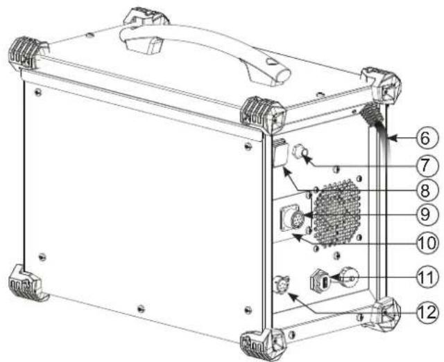
text_image
Technical diagram of an electronic device with numbered components for identification1
321 DC TRI :
text_image
Technical diagram of an industrial control unit with labeled components and control panel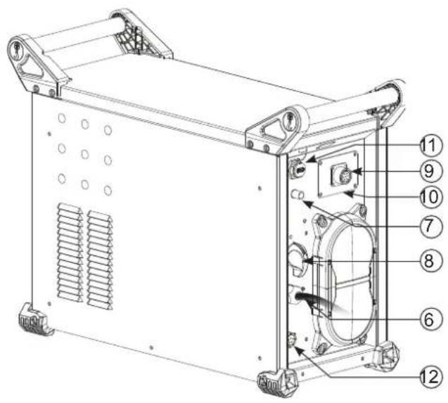
text_image
Technical diagram of a mechanical device with numbered components for identification||
text_image
VRD I % I % t Hz eWeld 230 A s % 1. V Hz kJ SETUP PRESS 3" Multi JOB ⑩ ⑨ ④ ⑤ 6 7 8AVERTISSEMENTS - RÈGLES DE SÉCURITÉ
CONSIGNE GÉNÉRALE

INSTALLATION - FONCTIONNEMENT PRODUIT
INTERFACE HOMME-MACHINE (IHM) (II)
text_image
I EWeld A s % Std V Hz kJ SETUP PRESS 3" S / JOBtext_image
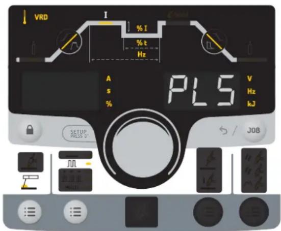
VOUT I % I % t Hz A s % PLS V Hz kJ SETUP PRESS 31 S / JOBtext_image
VDD I GVMU A s % SPL V Hz kJ SETUP PRESS 3" S / J08text_image
I % I % t Hz A s % EAC V Hz kJ SETUP PRESS 5° S / JOBStandard (courant constant)
text_image
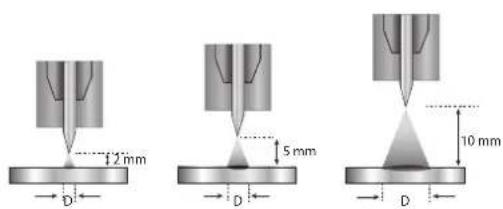
2mm 5mm 10mm D D Dtext_image
E. A s % On V Hz kJ SETUP PRESS 8" S / JOBtext_image
Bouton principal T1 T2text_image
P L DB 1 5 2 P torch 4 L torch 3 DB torch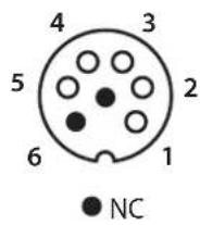
text_image
3 DB torch 4 L torch 2 2 5 1 DB + P torchtext_image
VRO I Cable A s % Std V Hz kJ SETUP PRESS 3' S / JOBtext_image
VRD I % I % t Hz A s % PL5 V Hz kJ SETUP PRESS 3° / JOBSEt UP → ●→ CaL Ibr.
SEt UP → ●→ EnE rGY →
√ → AFF
MODE ÉNERGIE
MESSAGES D'ERREUR, ANOMALIES, CAUSES, REMÈDES
These instructions must be read and fully understood before use. Do not carry out any alterations or maintenance work that is not directly specified in this manual.
The manufacturer shall not be liable for any damage to persons or property resulting from use not in accordance with the instructions in this manual. In case of problems or queries, please consult a qualified tradesperson to correctly install the product.
ENVIRONMENT
This equipment should only be used for welding operations performed within the limits indicated on the information panel and/or in this manual. These safety guidelines must be observed. The manufacturer cannot be held responsible in the event of improper or dangerous use.
The machine must be set up somewhere free from dust, acid, flammable gases or any other corrosive substances. This also applies to the machine's storage. Operate the machine in an open, or well-ventilated area.
Temperature range:
Use between -10 and +40°C (+14 and +104°F).
Store between -20 and +55°C (-4 and 131°F).
Air humidity:
Lower than or equal to 50% at 40°C (104°F).
Lower than or equal to 90% at 20°C (68°F).
Altitude:
Up to 1,000 m above sea level (3280 feet).
PROTECTING YOURSELF AND OTHERS
Arc welding can be dangerous and cause serious injury or death.
Welding exposes people to a dangerous source of heat, light radiation from the arc, electromagnetic fields (caution to those using pacemakers) and risk of electrocution, as well as noise and fumes.
To protect yourself and others, please observe the following safety instructions:

To protect yourself from burns and radiation, wear insulating, dry and fireproof clothing without lapels. Ensure the clothing is in good condition and that covers the whole body.

Wear protective gloves which provide electrical and thermal insulation.

Use welding protection and/or a welding helmet with a sufficient level of protection (depending on the specific use). Protect your eyes during cleaning procedures. Contact lenses are specifically forbidden.
It may be necessary to section off the welding area with fireproof curtains to protect the area from arc radiation and hot spatter. Inform people in the welding area not to stare at the arc rays or molten parts and to wear appropriate clothing for protection.

Wear noise protection headphones if the welding process becomes louder than the permissible limit (this is also applicable to anyone else in the welding area).
Keep hands, hair and clothing away from moving parts (the ventilation fan, for example).
Never remove the cooling unit housing protections when the welding power source is live, the manufacturer cannot be held responsible in the event of an accident.
Newly welded parts are hot and can cause burns when handled. When maintenance work is carried out on the torch or electrode holder, ensure that it is sufficiently cold by waiting at least 10 minutes before carrying out any work. The cooling unit must be switched on when using a water-cooled torch to ensure that the liquid cannot cause burns.
It is important to secure the working area before leaving it, in order to protect people and property.
WELDING FUMES AND GAS

The fumes, gases and dusts emitted by welding are harmful to health. Sufficient ventilation must be provided and an additional air supply may be required. An air-fed mask could be a solution in situations where there is inadequate ventilation.
Check the extraction system's performance against the relevant safety standards.
Caution: Welding in confined spaces requires safety monitoring from a safe distance. In addition, the welding of certain materials containing lead, cadmium, zinc, mercury or even beryllium can be particularly harmful. Remove any grease from the parts before welding.
Cylinders should be stored in open or well-ventilated areas. They should be stored in an upright position and kept on a stand or trolley.
Welding should not be carried out near grease or paint.
RISK OF FIRES AND EXPLOSIONS

Fully shield the welding area, flammable materials should be kept at least 11 metres away. Fire fighting equipment should be kept close to wherever the welding activities are being undertaken.
Beware of spatter or spark projection, as they are a potential source of fire or explosion, even through cracks.
Keep people, flammable objects and pressurised containers at a safe distance.
Welding in closed containers or tubes is to be avoided. If the containers or tubes are open, they must be emptied of all flammable or explosive materials (oil, fuel, gas residues, etc.).
Grinding work must not be directed towards the source of the welding current or towards any flammable materials.
GAS CYLINDERS
Gas escaping from cylinders can cause suffocation if there is too high a concentration of it in the welding area (ensure good ventilation).
The machine must be transported in complete safety: gas cylinders must be closed and the welding power source turned off. They should be stored upright and supported to limit the risk of falling.
Close the cylinder between uses. Beware of temperature variations and exposure to the sun.
The cylinder must not come into contact with flames, arcs, torches, earth clamps or any other sources of heat or ignition.
Be sure to keep it away from electrical and welding circuits. Never weld a pressurised cylinder.
When opening the cylinder valve, keep your head away from the valve and ensure that the gas being used is suitable for the welding process.
ELECTRICAL SAFETY

The electrical network used must be earthed. Use the recommended fuse size from the rating plate. An electric shock can be the source of a serious accident, whether directly or indirectly, or even death.
Never touch live parts connected to the live current, either inside or outside the power source casing unit (torches, clamps, cables, electrodes), as these items are connected to the welding circuit.
Before opening the machine's, disconnect it from the mains and wait two minutes to ensure that all the capacitors are fully discharged.
Do not touch the torch or the electrode holder and the earth clamp at the same time.
If the cables or torches become damaged, they must be replaced by a qualified and authorised person. Measure the cable cross-section according to the intended application. Always use dry and in-fact clothing to insulate yourself from the welding circuit. Alongside this, wear well-insulated footwear in all working environments.
EMC CLASSIFICATION

This Class A device is not intended for use in a residential environment where power is provided by the public low-voltage local supply network. Ensuring electromagnetic compatibility may be difficult at these sites due to conducted, as well as radiated, radio frequency interference.
TITAN 231 DC FV :
Provided that the impedance of the public low-voltage power supply network at the common coupling point is less than Zmax = 0.301 Ohms, this machine complies with IEC 61000-3-11 and can be connected to public low-voltage electrical supply. It is the responsibility of the fitter or operator of the equipment to ensure, by consulting the electricity distribution network provider if necessary, that the network impedance complies with impedance restrictions.
TITAN 321 DC TRI :
This equipment complies with the IEC 61000-3-11 standard.
TITAN 231 DC FV :
This equipment complies with the IEC 61000-3-12 standard.
TITAN 321 DC TRI :
This equipment does not comply with IEC 61000-3-12 and is intended to be connected to private low-voltage systems interfacing with the public supply only at the medium- or high-voltage level. On a public low-voltage power grid, it is the responsibility of the installer or user of the device to ensure, by checking with the operator of the distribution network, which device can be connected.
ELECTROMAGNETIC INTERFERENCES

An electric current passing through any conductor produces localised electric and magnetic fields (EMF). The welding current produces an electromagnetic field around the welding circuit and the welding equipment.
Electromagnetic fields (EMFs) can interfere with some medical devices, for example pacemakers. Protective measures must be taken for people with medical implants. For example, restricted access for onlookers or an individual risk assessment for welders.
All welders should use the following procedures to minimize exposure to electromagnetic fields from the welding circuit:
- position the welding cables together - securing them with a clamp if possible;
- position yourself (head and body) as far away from the welding circuit as possible,
- never wrap the welding cables around your body,
- do not position yourself between the welding cables. and keep both welding cables on your same side;
- connect the return cable to the workpiece, as close as possible to the area to be welded,
- do not work next to, sit or lean on the source of the welding current,
- do not transport the welding power source or wire feeder while welding.

Pacemaker users should consult a doctor before using this equipment.
Exposure to electromagnetic fields during welding may have other health effects that are not yet known.
RECOMMENDATIONS FOR ASSESSING THE WELDING AREA AND EQUIPMENT
General Information
It is the user's responsibility to install and use the arc welding equipment according to the manufacturer's instructions. If electromagnetic disturbances are detected, it is the user's responsibility to resolve the situation using the manufacturer's technical support. In some cases, this corrective action may be as simple as earthing the welding circuit. In other cases, it may be necessary to construct an electromagnetic shield around the welding current source and around the entire workpiece by setting up input filters. In any case, electromagnetic interference should be reduced until it is no longer an inconvenience.
Assessing the welding area
Before installing arc welding equipment, the user should assess the potential electromagnetic problems in the surrounding area. The following should be taken into account:
a) the presence of power, control, signal and telephone cables above, below and next to the arc welding equipment,
b) radio and television receivers and transmitters,
c) computers and other control equipment,
d) critical safety equipment, e.g. the protection of industrial equipment,
e) the health of nearby persons, e.g. those using of pacemakers or hearing aids,
f) the equipment used for calibrating or measuring,
g) the protection of other surrounding equipment.
The operator has to ensure that the devices and equipment used in the same area are compatible with each other. This may require further protective measures;
h) the time of day when welding or other operations are to be carried out.
The size of the surrounding area to be taken into account will depend on the building's structure and the other activities taking place there. The surrounding area may extend beyond the boundaries of the premises.
Assessment of the welding equipment
In addition to the assessment of the surrounding area, the arc welding equipment's assessment can be used to identify and resolve cases of interference. It is appropriate that the assessment of any emissions should include in situ procedures as specified in Article 10 of CISPR 11. In situ measurements can also be used to confirm the effectiveness of mitigation measures.
GUIDELINES ON HOW TO REDUCE ELECTROMAGNETIC EMISSIONS
a. Public mains power supply: Arc welding equipment should be connected to the mains power grid according to the manufacturer's recommendations. If any interference occurs, it may be necessary to take additional precautionary measures such as filtering the mains power supply. Consider protecting the power cables of permanently installed arc welding equipment within a metal pipe or a similar casing. The power cable should be protected along its entire length. The shield should be connected to the welding power source to ensure that there is good electrical contact between the conduit and the welding power source enclosure.
b. The maintenance of arc welding equipment: Arc welding equipment should be subject to routine maintenance as recommended by the manufacturer. All access points, service openings and bonnets should be closed and properly locked when the arc welding equipment is in use. The arc welding equipment should not be modified in any way, except for those modifications and adjustments mentioned in the manufacturer's instructions. The spark gap of arc starters and stabilisers should be adjusted and maintained according to the manufacturer's recommendations.
c. Welding cables: Cables should be as short as possible, placed close together either near or on the ground.
d. Equipotential bonding: Consideration should be given to linking all metal objects in the surrounding area. However, metal objects connected to the workpiece increase the risk of electric shocks to the user if they touch both these metal parts and the electrode. It is necessary to insulate the operator from such metal objects.
e. Earthing the workpiece: In cases where the part to be welded is unearthed for electrical safety reasons or due to its size and location, such as ship hulls or structural steel buildings, an earthed connection can reduce emissions in some cases, although not always. Care should be taken to avoid the earthing of parts which could increase the risk of injury to users or damage to other electrical equipment. If necessary, the workpiece's connection should be earthed directly, but in some countries where a direct connection is not allowed, the connection should be made with a suitable capacitor chosen according to national regulations.
f. Protection and protective casing: The selective protection and encasing of other cables and equipment in the surrounding area may limit interference problems. The safeguarding of the entire welding area may be considered for special applications.
THE TRANSPORTING AND MOVING OF THE MACHINE'S POWER SOURCE

The machine is equipped with a handle to easy transportation. Be careful not to underestimate its weight. The handle cannot be used to hang or attach the machine on something else.
Do not use the cables or torch to move the welding power source. It should be moved in an upright position.
Do not carry or transport the power source overhead of people or objects.
Never lift a gas cylinder and the welding power source at the same time. Their transportation requirements are different.
SETTING UP THE EQUIPMENT
- Place the welding power source on a floor with a maximum inclination of 10^ .
- Provide sufficient space to ventilate the welding power source and access the controls.
- Do not use in an area with conductive metal dust.
- The welding power source should be protected from heavy rain and not exposed to direct sunlight.
• The machine is IP23S rated, meaning: - its dangerous parts are protected from being entered by objects greater than 12.5 mm and,
- it is protected against rain falling at an angle of up to 60° from vertical, providing that any moving parts (fan) are stationary.
This product can therefore be stored outdoors in accordance with the IP23 protection rating.
The power cables, extensions and welding cables must be fully uncoiled to prevent overheating.

The manufacturer assumes no responsibility for damage to persons or objects caused by improper and dangerous use of this equipment.
MAINTENANCE / RECOMMENDATIONS


- Maintenance should only be carried out by a qualified person. Annual maintenance is recommended.
- Switch off the power supply by pulling the plug and wait two minutes before working on the equipment.. Inside the macine, the voltages and currents are high and dangerous.
- Regularly remove the cover and blow out any dust. Take advantage of the opportunity to have the electrical connections checked with an insulated tool by a qualified professional.
- Regularly check the condition of the power cable. If the power cable is damaged, it must be replaced by the manufacturer, the after sales service team or an equally qualified person to avoid any danger.
- Leave the welding power source vents free for air intake and outflow.
- Do not use this welding power source for thawing pipes, recharging batteries/storage batteries or starter motors.
INSTALLATION - USING THE PRODUCT
Only experienced personnel, authorised by the manufacturer, may carry out the machine's set-up. During set-up, ensure that the power source is unplugged from the mains. Series or parallel power source connections are not allowed. It is recommended to use the welding cables supplied with the unit in order to obtain the best possible product performance.
DESCRIPTION
This equipment is a power source for tungsten arc welding (TIG) in direct current (TIG DC) and for welding with coated electrodes (MMA).
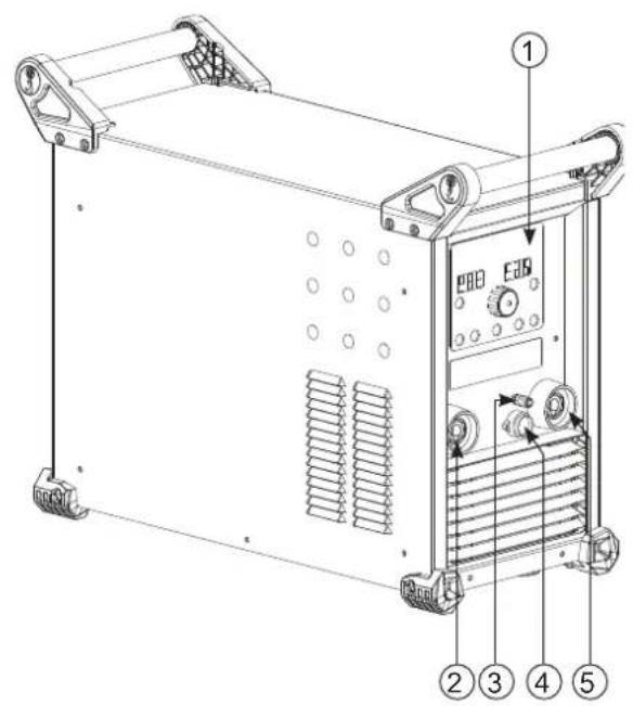
DESCRIPTION OF THE EQUIPMENT (I)
1- Keypad START / STOP switch (231 DC FV)
2- Positive polarity socket ON / OFF switch (321° DC TRI)
3- Torch gas connector 9- Remote control connector
4- Torch trigger connector Optional NUM TIG-1 kit connector (037960) = SAM automation
5- Negative polarity socket Optional NUM-1 kit connector (063938) = digital remote control
6- Power cable 11- USB connector for updates
7- Gas bottle connector 12- Connector for cooling unit (Koolweld 1)
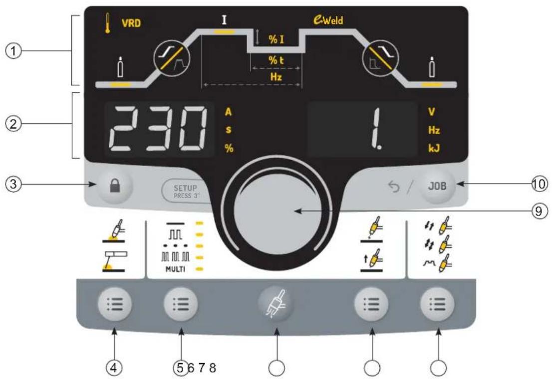
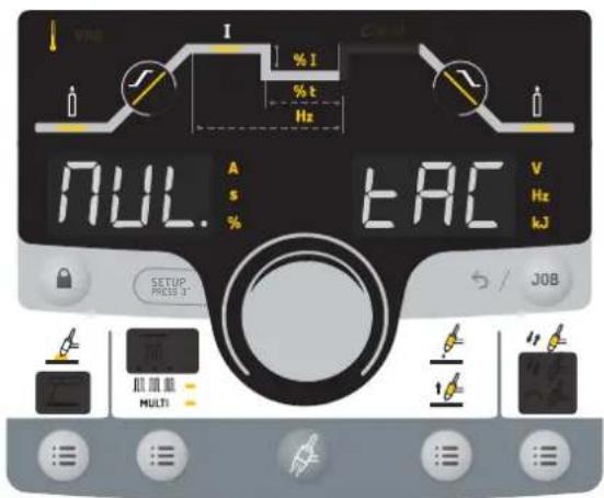
HUMAN-MACHINE INTERFACE (HMI) (II)
1- Welding cycle (9 accessible parameters) 6- Gas purge
2- Display and measurement units 7- Ignition methods
3- Lock / Unlock 8- Trigger modes
4- Welding processes (TIG / MMA) 9- Navigation and confirmation thumbwheel
5- Sub-processes 10- Job and back
POWER SWITCH
TITAN 231 DC FV:
This equipment is delivered with a single-phase 3-pole (P+N+PE) 230V 16A CEE17 socket. The machine is equipped with a «Flexible Voltage» system and can be powered by an earthed electrical installation between 110V and 240V (50 - 60 Hz).
TITAN 321 DC TRI:
This equipment is delivered with a 16 A socket type EN 60309-1 which must be connected to a three-phase 400V (50 - 60 Hz) power supply fitted with four wires and one earthed neutral.
The actual absorbed current (I1eff) for optimal operating conditions is indicated on the equipment. Check that the power supply and its protection (fuse and/or circuit breaker) are compatible with the current required to run the machine. In some countries, changing the plug may be necessary to ensure the machine's optimum performance.
This machine will enter a protection mode if the supply voltage is higher or lower than 15% of the specified voltage(s) (a fault code will appear on the keypad display).
TITAN 231 DC FV :
Starting is done by pressing the START/STOP switch (On), and stopping is done by pressing the same switch (Off)
TITAN 321 DC TRI :
Starting is done via an on / off switch set to I, and the stop is done by switching it to O.
Warning! Never switch off the power supply while the unit is under load.
- Fan performance: this product is equipped with an intelligent ventilation management system to minimise the noise of the machine. The fans will adjust their speed according to usage and the surrounding temperature. In MMA mode, the fan will run continuously. In TIG mode, the fan runs only during the welding phase and stops after cooling.
- Caution: Increasing the length of the torch or earth return cables beyond the maximum length specified by the manufacturer increases the risk of electric shock.
- The arc ignition and stabilisation device is designed for manual and mechanically guided operation.
CONNECTING TO A POWER SOURCE
This equipment can be powered by a generator, provided that the auxiliary power supply meets the following requirements:
- The voltage must be alternating, set as specified, and with a peak voltage of less than 700 V for the TITAN 321 DC and 400 V for the TITAN 231 DC FV.
- The frequency must be between 50 and 60 Hz.
It is vital to check these conditions as many generators produce high voltage peaks that can damage equipment.
USING EXTENSION LEADS
All extension leads must be of an appropriate length and cross-section to suit the voltage of the equipment. Use an extension lead that complies with national safety regulations.
| Input voltage | Length and thickness of the extension lead | ||
| < 45m > 45m | |||
| 231 DC FV | 110 V 2.5 mm ^2 4 mm ^2 | ||
| 230 V 2.5 mm ^2 | |||
| 321 DC TRI 40 | 0 V 2.5 mm ^2 | ||
GAS SUPPLY
This machine is equipped with two connectors. A connector for the gas cylinder inlet to the machine, and a connector for the gas outlet at the end of the torch. We recommend that you use the adapters supplied with your machine to ensure the best possible fit.
ACTIVATION OF THE VRD FUNCTION (VOLTAGE REDUCTION DEVICE)
The voltage reduction device (or VRD) is used to protect the welder. The welding current is only delivered when the electrode is in contact with the workpiece (low resistance). As soon as the electrode is removed, the VRD function lowers the voltage considerably.
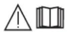
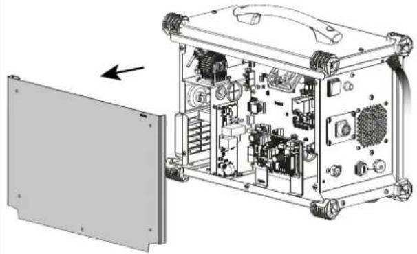
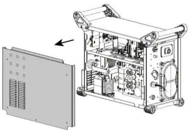
By default, the voltage reduction device is deactivated. In order to activate it, the user must open the product and complete the following procedure:
- DISCONNECT THE PRODUCT FROM THE POWER SUPPLY AND WAIT 5 MINUTES FOR SAFETY.
- Remove the side of the power source (see page at the end of the manual).
- Locate the control board and the VRD switch (see page at the end of the manual).
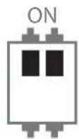
- Toggle the switch to the ON position.
- The VRD function is activated.
- Reinstall the side panel of the unit.
- The VRD icon on the interface (HMI) will be lit.
To deactivate the VRD function, simply flip the switch back to the opposite position.
FUNCTION, MENU AND ICON DESCRIPTIONS
| Function Icon MMA DC TIG Comments | ||||
| Thermal protection x x Symbol to indicate the thermal protection status. | thermal | protection status. | ||
| VRD | VRD | x | Ignition voltage reduction device. | |
| Pre-gas | x Time taken to purge the torch and create the gas shield before ignition (sec). | |||
| Up-slope current | x Up-slope current (sec). | |||
| Welding current | I | x x Welding current (A). | ||
| E-Weld x Continuous energy w#d#lal mode with compensation for arc length variations. | |||
| Down-slope current x Down-slope current. | |||
| Post-gas x | Duration of the gas protection after the arc is extinguished. It protects the weld pool and the electrode against oxidisation when the metal is cooling down (sec). | ||
| Cold current x x | Second «cold» welding current in TIG Standard, 4TLOG, TIG Pulse and MMA Pulse (%). | ||
| Pulse balance x Balance between cold current duration and pulse duration (%). | |||
| PULSE Frequency x x Frequency of the Pulse in Pulse mode (Hz). | |||
| HotStart x Adjustable overcurrent at the beginning of the welding (%) | |||
| ArcForce x Overcurrent delivered during welding (-10 to +10). | |||
| Ampere (unit) x x Amperage unit current adjustment and welding current display. | |||
| Time (unit) x x The unit of second or timing settings or the display of welding duration. | |||
| Percentage (unit) x x Unit of percentage for proportional settings. | |||
| Volt (unit) | V | x x Voltage unit for the display of the welding voltage. | |
| Hertz (unit) | WHT | x x Hertz unit for frequency settings. | |
| KiloJoules (unit) | C | x x Unit in KiloJoules for the welding energy display. | |
| LOCK | x x Lock/unlock | button (press for 3 seconds). | |
| JOB and return | x x | Button to access the JOB menu (save and recall a program).This button also returns to the previous screen.Direct return mode (ready to weld)By pressing the triggerLong press on the navigation wheel | |
| TIG process | Arc welding with a non-melting tungsten electrode under protective gas shiel-ding. | ||
| MMA process x Arc welding with consumable coated electrode | |||
| Standard mode | x x Smooth current | ||
| Pulse Mode | x x Pulsed current | ||
| Spot Mode | x Smooth tacks | ||
| Tack Mode | x Pulse + smooth tacking | ||
| Multi Spot Mode | MULTI + ... | x Repeated smooth tacking | |
| Multi Tack Mode | MULTI + ... | x Repeated pulsed tacking | |
| HF ignition | x High-frequency ignition | ||
| LIFT ignition | x Ignition with contact | ||
| Touch HF ignition | Time-delayed high-frequency ignition | ||
| 2T | x 2T trigger mode. | ||
| 4T | x 4T trigger mode. | ||
| 4T LOG | x 4T LOG trigger mode. | ||
| Gas purge | x Gas purge activation button for the torch. | ||
THUMBWHEEL NAVIGATION


Rotating the thumbwheel allows
- adjustment to the welding current
- to change a parameter of the welding cycle
Pressing the thumbwheel allows - access to the welding cycle by selecting the first parameter
- access to the parameter settings and confirm the modification
TIG (GTAW) WELDING MODE
INSTALLATION AND GUIDANCE
- DC TIG welding requires a protective gas shield (Argon).
- Connect the earth clamp to the positive (+) plug connector. Connect the torch power cable to the
negative (-) socket, along with the torch button(s) and gas connector(s). - Ensure that the torch is properly fitted and that the consumables (clamps, collet bodies, diffusers and nozzles) are not worn out.
- The electrode is determined by the welding current of the TIG process.
RECOMMENDED COMBINATIONS
| (mm) | Current (A) ∅ Electrode (mm) ∅ Nozzle (mm) Argon flow rate (L/min) | ||||
| DC TIG | 0.3 - 3 3 - 75 1 | 6.5 6 - 7 | |||
| 2.4 - 6 60 - 150 | 1.6 8 6 - 7 | ||||
| 4 - 8 100 - 200 | 2 9.5 7 - 8 | ||||
| 6.8 - 8.8 | 170 - 250 | 2.4 | 11 | 8 - 9 | |
| 9 - 12 | 225 - 320 | 3.2 12.5 | 9 - 10 | ||
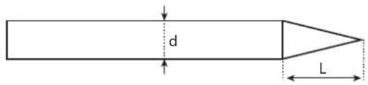
ELECTRODE SHARPENING
For optimum results, it is advised to use an electrode sharpened in the following way:
text_image
d LL = 3 x d for a low current.
L = d for a high current
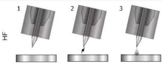
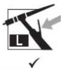
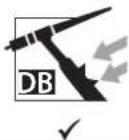
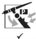
SELECT IGNITION MODE
Lift: contact ignition (for applications sensitive to HF disturbances)
HF: high frequency ignition without contact between the tungsten electrode and the workpiece.
Touch.HF: time-delayed high frequency ignition after contact between the tungsten electrode and the workpiece
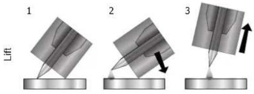
text_image
1 Lift 2 31- Position the torch nozzle and electrode tip on the workpiece and press the torch button.
2- Tilt the torch until a distance of about 2-3 mm separates the tip of the electrode and the workpiece. The arc starts.
3- Move the torch to the regular position to start the welding cycle.
text_image
1 2 31- Place the torch in the welding position above the workpiece (distance of about 2-3 mm between the electrode tip and the workpiece).
2- Press the torch button (the arc is initiated without contact using high voltage HF ignition pulses).
3- The initial welding current circulates, and the process continues as per the welding cycle.
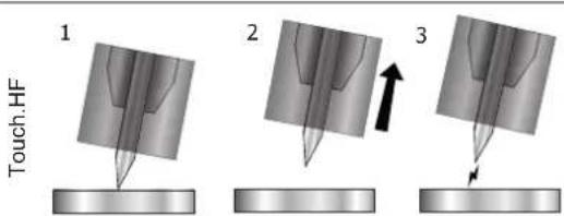
text_image
Touch.HF 1 2 31- Position the electrode tip on the workpiece and press the torch button.
2- Lift the electrode from the workpiece.
3- After a delay of 0.2s, the arc is initiated without contact using high voltage HF ignition pulses, the initial welding current circulates and the weld continues according to the welding cycle.
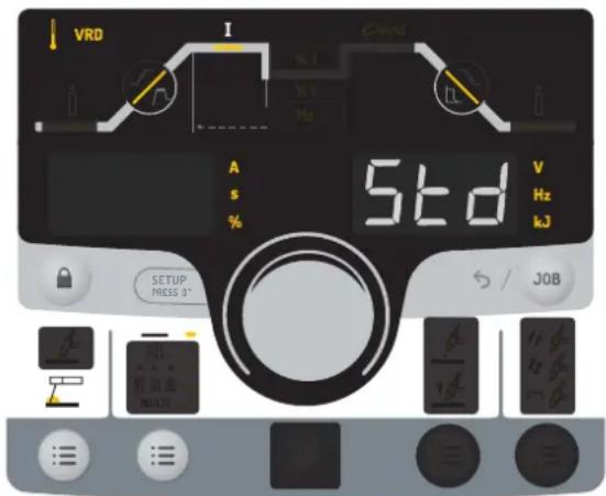
TIG WELDING PROCESSES
- Standard
The Standard TIG mode provides high quality welding on most ferrous materials such as steel and stainless steel, but also on copper and its alloys, and titanium etc. The various current and gas management options give you complete control over the welding process, from ignition through to the final cooling of the weld bead.
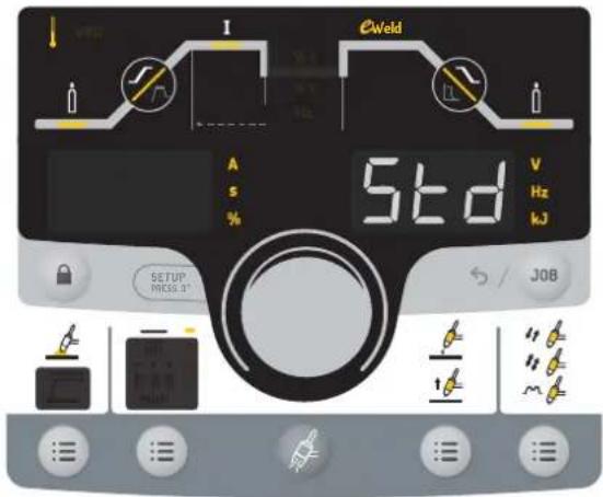
text_image
E Weld A S % Std V Hz kJ SETUP PRICE 3° S / JOBThe grayed-out areas are not available in this mode.
- Pulse
Pulse current welding mode consists of a sequence of high current pulses (I, welding pulse) followed by low current pulses (I_Cold, workpiece cooling pulse). Pulse mode allows pieces to be assembled while limiting temperature rises and warping. Idéal aussi en position.
Example:
The welding current (I) is set to 100 A and % (I_cold) = 50%, i.e. cold current = 50% × 100 A = 50.
F(Hz) is set to 10Hz, the period of the signal will be 1/10Hz = 100ms every 100ms, during this period a pulse at 100A then another at 50A will follow..
Recommendations:
Choice of frequency:
- If welding with manual filler metal, then F(Hz) is synchronised to the filler action,
- If thin without filler (< 0.8 mm), F(Hz) >> 10Hz
- Positional/vertical welding, then F(Hz) 5 < 100Hz
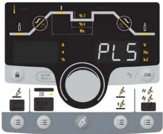
text_image
PL5 A s % SETUP PRESS 3' V Hz kJ JOBThe grayed-out areas are not available in this mode.
SPECIAL TIG WELDING PROCESSES
- Spot (Mode adjustable directly from the welding cycle)
This mode is for spot welding, which allows workpieces to be pre-assembled prior to welding. Spot welding can be done manually using the trigger or timed with a predefined spot welding period. Spot welding allows for better reproducibility and non-oxidised weld points.

text_image
I Cable A S % 5PT V Hz kJ SETUP PRESS 9" JOBThe grayed-out areas are not available in this mode.
The tacking time is in the welding cycle after the gas station.
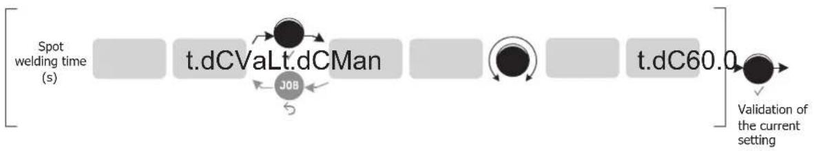
flowchart
graph LR
    A["Spot welding time (s)"] --> B["t.dCVaLt.dCMan"]
    B --> C["JOB"]
    C --> D["t.dC60.0"]
    D --> E["Validation of the current setting"]
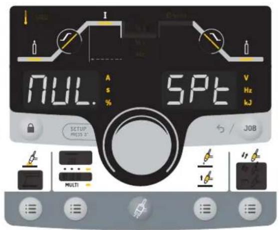
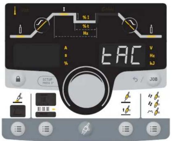
- Multi-Spot (Mode adjustable directly from the welding cycle) This is a spot welding mode similar to TIG Spot, but with defined tacking and hold times, as long as the trigger is held down.
text_image
I NUL. A S % SPT V Hz kJ SETUP PRESS 3" Multi J08The grayed-out areas are not available in this mode.
The tacking time is in the welding cycle after the gas station.
flowchart
graph LR
    A["Spot welding time (s)"] --> B["t.dCVaLt.dCMan"]
    B --> C["t.dC60.0"]
    C --> D["Validation of the current setting"]
    E["Duration between 2 points (s)"] --> F["t.MU.Val"]
    F --> G["t.MU.0"]
    G --> H["t.MU.25"]
    H --> I["Validation of the current setting"]
    J["Job"] --> B
    K["Job"] --> F
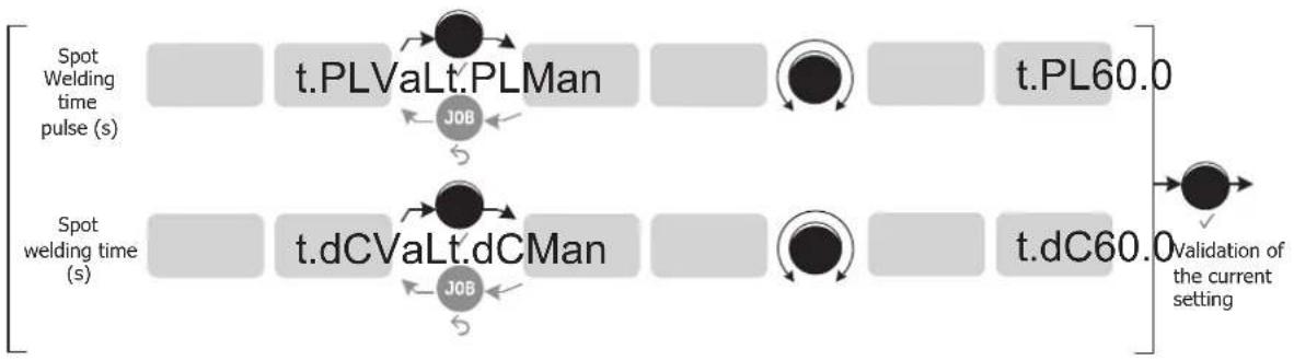
- Tack (Mode adjustable directly from the welding cycle) This welding mode also allows for the pre-assembly of workpieces before welding, but in two stages this time: the first phase is pulsed DC to concentrate the arc for better penetration, followed by a second phase in standard DC to widen the arc, and therefore the weld pool, to ensure the spot. The adjustable times of the two phases allow for better repeatability and non-oxidised points.
text_image
I % I % t Hz A s % EAC V Hz kJ SETUP PRESS 3" S / JOBThe grayed-out areas are not available in this mode.
The tacking time is in the welding cycle after the gas station.
flowchart
graph LR
    A["Spot Welding time pulse (s)"] --> B["t.PLVaLt.PLMan"]
    B --> C["t.PL60.0"]
    D["Spot welding time (s)"] --> E["t.dCVaLt.dCMan"]
    E --> F["t.dC60.0"]
    G["Validation of the current setting"] --> H["End"]
    style A fill:#f9f,stroke:#333
    style D fill:#f9f,stroke:#333
    style B fill:#ccf,stroke:#333
    style E fill:#ccf,stroke:#333
    style F fill:#ccf,stroke:#333
    style H fill:#cfc,stroke:#333
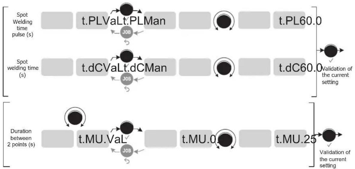
- Multi-Tack (Mode adjustable directly from the welding cycle) This is a tacking mode similar to TIG Tack, but with defined spot and hold times for as long as the trigger is held down.
text_image
VAG I % I % t Hz NULL. EAC V Hz kJ SETUP PRICE 3" S / JOB ALL MULTIThe grayed-out areas are not available in this mode.
flowchart
graph LR
    A["Spot Welding Time Pulse (s)"] --> B["t.PLValt.PLMan"]
    B --> C["t.PL60.0"]
    D["Spot Welding Time (s)"] --> E["t.dCValt.dCMan"]
    E --> F["t.dC60.0"]
    G["Duration between 2 points (s)"] --> H["t.MU.Val"]
    H --> I["t.MU.0"]
    I --> J["t.MU.25"]
    style A fill:#f9f,stroke:#333
    style D fill:#f9f,stroke:#333
    style G fill:#f9f,stroke:#333
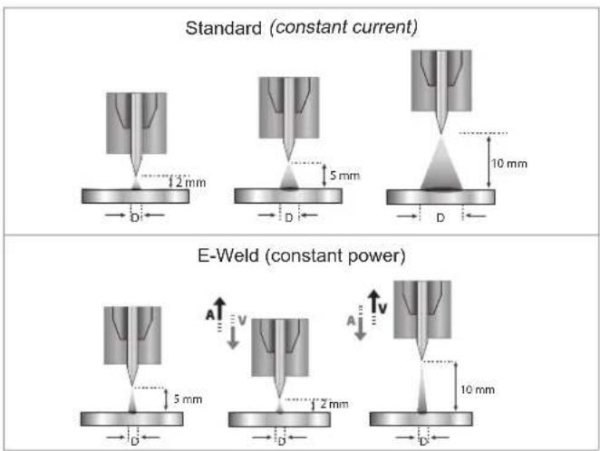
• E-Weld (activated on the welding cycle)
This mode allows for constant power welding by measuring arc length variations in real time to ensure consistent bead width and penetration. In cases where the assembly requires careful control of the welding energy, E-Weld mode guarantees that the machine will respect the welding power regardless of the torch's position in relation to the workpiece.
text_image
Standard (constant current) E-Weld (constant power)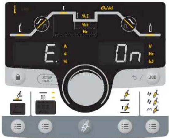
text_image
I % I % t Hz E. A s % On V Hz kJ SETUP MELD 3° S / JOBThe grayed-out areas are not available in this mode.
TIG - ADVANCED MENU
It is possible to access the advanced weld cycle settings. To access these advanced settings:
1- Press and hold the thumbwheel (> 3 seconds)

By scrolling with the thumbwheel, the following advanced settings can be selected:
| Parameter Setting Standard Pulse | Spot welding | Multi Spot | Tack | Multi Tack | ||||
| I.St I_Start | Bearing current at the start of the weld | 1 - 200 % X X | - | The stage before the current upslope. | ||||
| t.St T_Start | Dwell time at the start of the weld | 0.00 - 60 sec. X X | - | |||||
| I.So I_Stop | Bearing current at the end of the weld | 1 - 100 % X X | - | Stage after the current downslope. | ||||
| t.So T_Stop | Dwell time at the end of the weld | 0.0 - 60 sec. X X | - | |||||
| Sha | Pulse waveform | Sin Sinusoidal | - X | - | The square waveform is the traditional method of pulse welding, but is noisy at high frequencies. Other shapes are available to suit specific penetration and noise requirements. | |||
| tri Triangle | ||||||||
| Sqa Square | ||||||||
| trA Trapezium | ||||||||
CHOICE OF ELECTRODE DIAMETER
| Electrode ∅ (mm) | DC TIG | |
| Pure tungsten | Tungsten with oxides | |
| 1 | 10 > 75 | 10 > 75 |
| 1.6 | 60 > 150 | 60 > 150 |
| 2 | 75 > 180 | 100 > 200 |
| 2.5 | 130 > 230 | 170 > 250 |
| 3.2 | 160 > 310 | 225 > 330 |
| 4 | 275 > 450 | 350 > 480 |
| Approx. = 80 A per mm ∅ | ||
COMPATIBLE TORCHES AND TRIGGER BEHAVIOUR
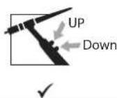
Trigger Double Button Double Button + Potentiometer Up & Down
For the 1-button torch, the button is called the «Main button».
For the 2-button torch, the first button is called the «Main button» and the second one is called «Secondary button».
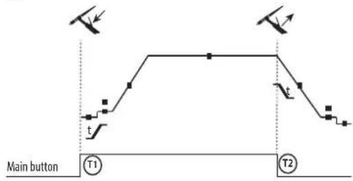
• 2T
text_image
Main button T1 T2T1 - The main button is pressed, the welding cycle starts (Pre-Gas, I_Start, upslope and welding).
T2 - The main button is released, the welding cycle is stopped (downslope, I_Stop, Post-Gas).
For two-button torches in T2 only, the secondary button is treated as the main button.
• 4T

flowchart
graph TD
    A["Main button"] --> B["T1"]
    B --> C["T2"]
    C --> D["t"]
    D --> E["T3"]
    E --> F["T4"]
    style A fill:#f9f,stroke:#333
    style B fill:#ccf,stroke:#333
    style C fill:#cfc,stroke:#333
    style D fill:#fcc,stroke:#333
    style E fill:#cff,stroke:#333
    style F fill:#ffc,stroke:#333
T1 - The main button is pressed, the cycle starts from Pre-Gas and stops at the I_Start phase.
T2 - The main button is released, the cycle continues to upslope and welding.
T3 - The main button is pressed, the cycle goes to downslope and stops in the I_Stop phase.
T4 - The main button is released, the cycle ends with the Post-Gas.
NB: for double button and double button + potentiometer torches => «up/weld current» button turns on the potentiometer, the «down» button turns it off.
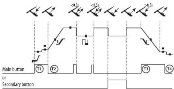
• 4T LOG
text_image
Main button or Secondary button T1 T2 T3 T4 <0.5s <0.5s >0.5sT1 - The main button is pressed, the cycle starts from Pre-Gas and stops at the I_Start phase.
T2 - The main button is released, the cycle continues to upslope and welding.
LOG: This function is used during welding:
- a quick press of the main button (<0.5 s) switches the current from I-welding to I-cold and vice versa.
- if the secondary button is pressed, the current switches from I-welding to I-cold.
- if the secondary button is left unpressed, the current switches from I-cold to I-welding.
T3 - After holding down the main button (>0.5 s), the cycle begins to downslope and stops at the I_Stop phase.
T4 - The main button is released and the cycle ends with Post-Gas.
For double button or double trigger + potentiometer torches, the «high» trigger has the same function as the single trigger torch. The «low» trigger, when held down, switches to the cold current. When using a potentiometer torch, the welding current can be adjusted between 50% and 100% of the value displayed. The Up & Down function allows the current at the torch to be set very precisely (the complete current range is adjustable).
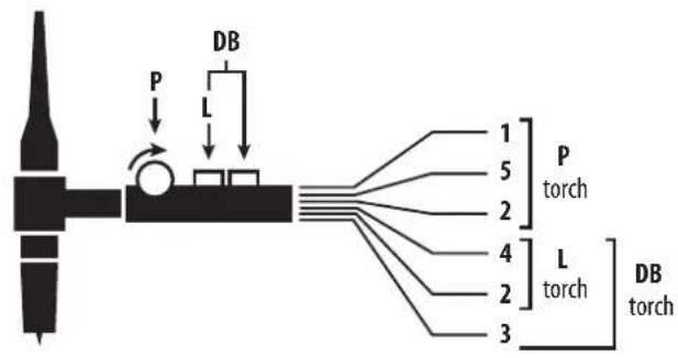
COMMAND TRIGGER CONNECTOR
text_image
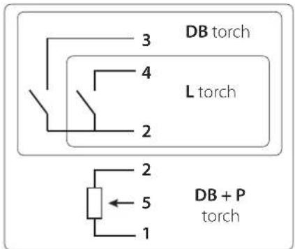
DB P L 1 5 2 4 L 3 P torch L torch DB torch

text_image
3 DB torch 4 L torch 2 2 5 1 DB + P torchWiring diagram of the torch Wiring diagram according to the type of torch
| Torch type Wire description Pin | ||||
| Torch double button + potentiometer | Torch double button Torch | with trigger | Common/Earth 2 | |
| Button 1 4 | ||||
| Button 2 3 | ||||
| Common/Potentiometer earth | 2 | |||
| 10 V 1 | ||||
| Cursor 5 | ||||
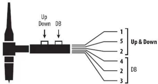
flowchart
graph TD
    A["Device"] -->|Up Down| B["DB"]
    A -->|Up & Down| C["DB"]
    B --> D["1"]
    B --> E["5"]
    B --> F["2"]
    B --> G["4"]
    B --> H["2"]
    B --> I["3"]

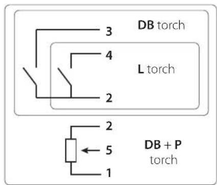
text_image
4 3 5 2 6 1 NC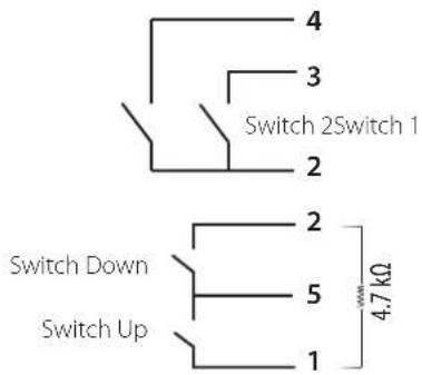
text_image
4 3 Switch 2Switch 1 2 Switch Down 5 1 4.7 kΩ Switch UpWiring diagram of the Up & Down torch Electrical diagram of the Up & Down torch
| Torch type Wire description Pin | ||
| Up & Down torch | CommonSwitch 1 & 2 | 2 |
| Switch 1 | 4 | |
| Switch 2 | 3 | |
| CommonSwitch Up & Down | 5 | |
| Switch Up | 1 | |
| Switch Down | 2 |
MANUAL GAS PURGE

The presence of oxygen in the torch can lead to a decline in mechanical performance, resulting in reduced corrosion resistance. To purge the gas from the torch, briefly press the button on the keypad. To stop the gas purge, briefly press the button or trigger again. If you forget to re-press the button, the gas purge stops automatically after 20 seconds.
During the gas purge, the display shows: Pur. GAS
MMA (SMAW) WELDING MODE
INSTALLATION AND GUIDANCE
- Plug the cables, electrode holder and earth clamp into the plug connections.
- Respect the electrical polarities and the strength of the welding power indicated on the electrode boxes.
- Remove the coated electrode from the electrode holder when the welding power source is not in use.
- The equipment is fitted with 3 inverter-specific features:
- Hot Start provides an overcurrent at the beginning of the welding process.
- Arc Force creates an overcurrent which prevents the electrode from sticking to the weld pool.
- The Anti-Stick technology makes it easier to unstick the electrode from the metal.
MMA WELDING PROCESSES
- Standard
This welding method is suitable for most applications. It is suitable for welding with all types of coated, rutile, basic and cellulosic electrodes and on all materials: steel, stainless steel and cast iron.
Recommendations:
- Use low Hot Start for thin sheets, and high Hot Start for thicker sheets and difficult metals (dirty or oxidised parts).
- The Arc Force can be adjusted from -10 to +10 It should be considered in conjunction with the choice of electrode type selected in the Advanced Menu (see Advanced Menu).
| Adjustable values | ||
| HotStart | Electrode types | Arc Force |
| 0 - 100 % | RutileBasicCellulosic | -10 > +10 |
The selection of the electrode type is in the welding cycle, after current setting (I).
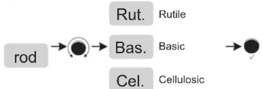
flowchart
graph LR
    A["rod"] --> B["Rut. Rutile"]
    B --> C["Bas. Basic"]
    C --> D["Cel. Cellulosic"]
text_image
VRD I % I % I Hz A s % Std V Hz kJ SETUP PRESS 3' S / JOBThe grayed-out areas are not available in this mode.
- Pulse
This welding mode is recommended for applications in a vertical upright position (PF). Pulsing keeps the weld pool colder while still promoting material transfer. Without pulsing, vertical rising welds require a «fir tree» movement, i.e. a challenging triangular movement. With MMA Pulse, this movement is not necessary, and depending on the thickness of your workpiece, a straight upward movement may be sufficient. However, if you want to enlarge your weld pool, a simple sideways movement similar to flat welding will be adequate. If this is the case, you can set the frequency of your pulse current on the display. This process offers greater control of vertical welding tasks.
Recommendations:
- Use low Hot Start for thin sheets, and high Hot Start for thicker sheets and difficult metals (dirty or oxidised parts).
- The Arc Force can be adjusted from -10 to +10 This should be considered in combination with the electrode type selected in the Advanced Menu (see below).
| Adjustable values | ||||
| HotStart | Electrode types | Arc Force | % ICold current | HzPulse frequency |
| 0 - 100 % | RutileBasicCellulosic | -10 > +10 + | 20 > +80% 0.4 - 500 Hz | |
Rut.
Rutile
rod
Bas.
Basic

Cel.
Cellulosic
text_image
VRD I % I % t Hz A s % PL5 V Hz kJ SETUP PRESS 3° S / JOBThe grayed-out areas are not available in this mode.
ADJUSTING THE WELDING INTENSITY
The following settings indicate the usable current range depending on the type and diameter of the electrode. The ranges are quite broad, as they vary depending on the application and the welding position.
| Electrode ∅ (mm) Rutile E6013 (A) Basic E7018 (A) Cellulosic E6010 (A) | |||
| 1.6 30-60 30-55 - | |||
| 2.0 50-70 50-80 - | |||
| 2.5 60-100 80-110 60-75 | |||
| 3.15 80-150 90-140 85-90 | |||
| 4.0 100-200 125-210 120-160 | |||
| 5 150-290 200-260 110-170 | |||
| 6.3 200-385 220-340 - | |||
CHOOSING COATED ELECTRODES
- Rutile electrodes: very easy to use in any position.
- Basic electrodes: it can be used in all positions and is suitable for safety work due to its increased mechanical properties.
- Cellulosic electrodes: very dynamic arc with a high melting speed, its suitability for use in all positions makes it ideal for pipeline work.
MMA - ADVANCED MENU
It is possible to access the advanced weld cycle settings. To access these advanced settings:
1- Press and hold the thumbwheel (> 3 seconds)
2- SET UP → ●→ Con FIG.
By scrolling with the thumbwheel, the following advanced settings can be selected:
| Parameter | Setting | Standard | Pulse | ||
| H.S.t | HotStart duration | 0.0 - 2.0 sec. | X | X | HotStart is an overcurrent on ignition that prevents the electrode from sticking to the workpiece. |
| A.St. | Anti-Sticking | ON-OFF | X | X | The anti-stick function is useful for removing the electrode safely in the event it sticks to the workpiece (the current is switched off automatically). |
LOCK / UNLOCK
The product lock prevents accidental adjustment.
Locking:
To lock the product, hold down the button 🔒 for more than 3 seconds. The display briefly shows Loc and the product is now locked. No buttons are enabled, and the thumbwheel allows a variation around the current value previously set to +/- a percentage defined by the tolerance parameter tol.
Unlocking:
To unlock the unit, press and hold the button, the display will show Cod. Enter the code (000 by default) with the thumbwheel to unlock the machine.
Un Loc
The code is accepted. All buttons are reactivated.
Cod. Err
The code is incorrect.
Ser. Cod. After 3 incorrect attempts to enter the code, the display shows «Ser. Cod.» for 2 seconds. The display then shows a flashing 6-digit code that must be entered with the thumbwheel to release the lock. This code is made up of six digits and cannot be changed. It is: 314159.
i
The default code 000 can be changed via the SETUP menu. See following pages for details.
MEMORISING AND RECALLING JOBS
• Job Out/Job In
The settings in use are automatically saved and remembered the next time you turn on the machine.
In addition to the current settings, it is possible to save and recall «JOB» configurations.
There are 50 JOBS for each welding process, with memory storage for:
- The main parameter,
- The secondary parameter (MMA, TIG),
- Sub-processes and trigger modes.
Recall an existing «Job Out» configuration:
- Press the «JOB» button on the keypad, select it using the thumbwheel Job Out
- Confirm by pressing the button on the thumbwheel,
- The display shows the previously stored JOB number (01 to 50) flashing. Si aucun JOBS n'est créé, l'afficheur indique «Empty»
- Turn the thumbwheel to select the JOB you wish to retrieve,
- Confirm by pressing the button on the thumbwheel,
- The recall is carried out / immediate exit from the menu.
Save a setting «JOB IN»:
- Press the «JOB» button on the keypad, select it using the thumbwheel Job In
- Confirm by pressing the button on the thumbwheel,
- The display indicates a memory slot (01 to 50) while flashing. Fast blinking = JOB already in use. Slow flashing = free space.
- Turn the thumbwheel to select a memory slot for the configuration to be saved,
- Confirm by pressing the button on the thumbwheel,
- The entry is completed / immediate exit from the menu occurs.
Supprimer un JOB :
- Press the «JOB» button on the keyboard, select with the thumbwheel Job In
- Confirm by pressing the button on the thumbwheel,
- Turn the wheel to select the JOB you wish to delete and hold down the «JOB» button on the keyboard for 3s.
- A DELETE message is displayed on the keyboard, the previously selected JOB is now deleted.
- Quick Load «q.L. «:
Quick Load is a non-welding JOB retrieval mode (50 max) and is only available when using TIG. JOB recalls are performed by briefly releasing (<0.5s) the torch buttons.
This mode is accessed via the «JOB» menu, then the submenu q.L. Disabled by default q.L. OFF, the user activates this mode by entering the JOB number at the end of the sequence to be recalled (the sequence starts at the first JOB). At least 2 JOBS must be saved prior to that.
Eg: if JOBS 2, 5, 7 and 10 have been created and the user enters number 7, then the JOBS recalled will be 2, 5 and 7.
When the mode is activated, the first JOB is recalled and displayed on the HMI (in the example: JOB 2).
The recall is looped: when the last JOB in the queue is reached (example: JOB 7), the following one will be the first in the sequence (in the example: JOB 2).
Welding is activated by pressing the button for longer than 0.5s.
The HMI will behave with the relevant information:
- The JOB is permanently displayed as well as the parameters (TIG LIFT/HF..., 2T/4T.../ Pulse/Spot...).
- The weld cycle is accessible and can be modified (the JOB is adjustable*),
- The menus are accessible and modifiable. Example:
- JOB 5, amended, JOB IN / JOB 5, the JOB is overwritten with the new parameters and saved.
- JOB 5, amended, JOB IN / non-existent JOB, it will be integrated into the current q.L. if, and only if, the new JOB X is a smaller number than the JOB already entered.
- The JOB recall is disabled when navigating the welding cycle settings or one of the two menus.
* A JOB is de-set by a HMI action (welding parameter adjustment, JOB recall ...), welding is then allowed with the new settings. If a JOB recall is initiated, then the first JOB in the sequence is recalled.
CHAINING «CHn»:
Chaining is a complex JOB recall mode (50 max) and only possible in TIG Standard and TIG Pulse mode (all the JOBs set in 2T are changed to 4T):
- When not welding, briefly (<0.5s) releasing the torch button will scroll through all stored JOBS one by one. On reaching the last item in the list, the selection goes back to the first item.
- Welding is activated by pressing the top button for 0.5s, whereas in the standard mode it is activated immediately upon pressing this button.
- During welding, briefly releasing the button (<0.5s) will recall a defined number of consecutive JOBs, also known as the sequence, starting from the previously recalled JOB when not welding.
This mode is accessed via the «JOB» menu, then the submenu CHn. Disabled by default CHn OFF, the user activates this mode by entering a number of JOBS that make up the sequence. At least 2 JOBS must be saved prior to that. Spot welding jobs (SPOT, TACK), are no longer part of the list of saved JOBS (they are transparent).
Example: if JOBS 1 to 50 have been created and the user has entered number 3 in the submenu «CHn»:
- When the sub-mode is activated and not welding, briefly releasing the torch button will scroll through the JOBS one by one from the 1st to the 50th and then loop back again. Here the user displays the JOBS and chooses the 10.
- Pressing the button for over 0.5s allows to start welding with JOB 10 (first of the sequence) and briefly releasing it loads JOB 11 and then JOB 12 (these 3 JOBS make the sequence).
- When the welding stops, the JOB 10 is loaded and displayed on the interface (this saves the user the task of having to show all the JOBS again).
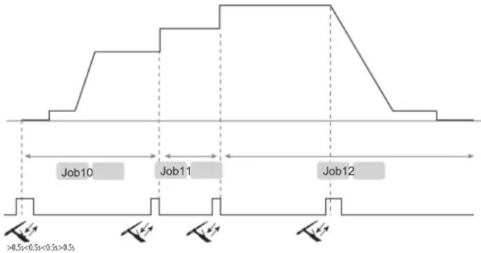
text_image
Job10 Job11 Job12 >0.5s<0.5s<0.5s>0.5sThe HMI will behave with the relevant information:
- The JOB is permanently displayed as well as the parameters (TIG LIFT/HF, 4T, Pulse...).
- The weld cycle is accessible and can be modified (the JOB is adjustable*),
- The menus are accessible and modifiable. Eg:
- JOB 5, amended, SAVE IN / JOB 5, the JOB is overwritten with the new parameters and saved.
- JOB 5, amended, SAVE IN / non-existent JOB, it will be integrated into the current q.L. if, and only if, the new JOB X is a smaller number than the JOB already entered.
- When currently browsing the welding cycle or one of the two menus, the JOB recall function is disabled.
- During welding, when recalling a JOB of the sequence, the screen displays JOB X for 1s.
* A JOB is changed by action on the interface without saving, the welding is authorised without taking into account the modifications on the JOB recalled.
OPTIONAL REMOTE CONTROL
- RC-HA1 Analogue remote control (ref. 045675 / 066625):
An analogue remote control can be connected to the power source via the socket (I-9).
This remote control allows the current to be adjusted from 50% to 100% of the set value. In this setup, all modes and features of the power source are accessible and configurable.
- Remote control pedal RC-FA1 (ref. 045682):
A remote control pedal can be connected to the power source via the socket (I-9).
The foot pedal allows the current to be varied from minimum to 100% of the current setting. In TIG, the machine only works in 2T mode. Furthermore, the increase and decrease of the current is no longer managed by the power source (inactive function) but by the operator via the foot pedal.
Connection:
1- Connect the remote control to the socket (I-9).
2- The interface automatically detects the remote control and displays a selection of options accessible with the thumbwheel:
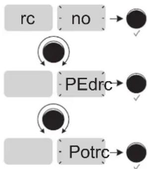
flowchart
graph TD
    A["rc"] --> B["no"]
    B --> C["●"]
    D["PEdrc"] --> E["●"]
    F["Potrc"] --> G["●"]
A command is shown but not active.
Selection of a pedal-type remote control.
Remote control with potentiometer selection.
Pressing the thumbwheel confirms the remote control selection, and switches back to welding mode.
Connectivity
The machine is equipped with a female connector for a remote control.
The specific 7-point male connector (optional ref. 045699) can be used to connect the different types of remote control. For wiring, follow the diagram below.
| Type of remote control Wire description Pin | ||||
| C5 | Foot pedal Manual | remote control | 10 VA | |
| Cursor | B | |||
| Common/Earth | C | |||
| Switch | D | |||
| AUTO-DETECT | E | |||
| ARC ON | F | |||
| REG I | G | |||
C5:
From a previously created C5 list of 5 JOBs, this simple automation mode using the Remote Control connector allows JOBs to be recalled via a PLC (see note on the website -https://planet.gys.fr/pdf/spdoc/fr/CONNECT_5.pdf).
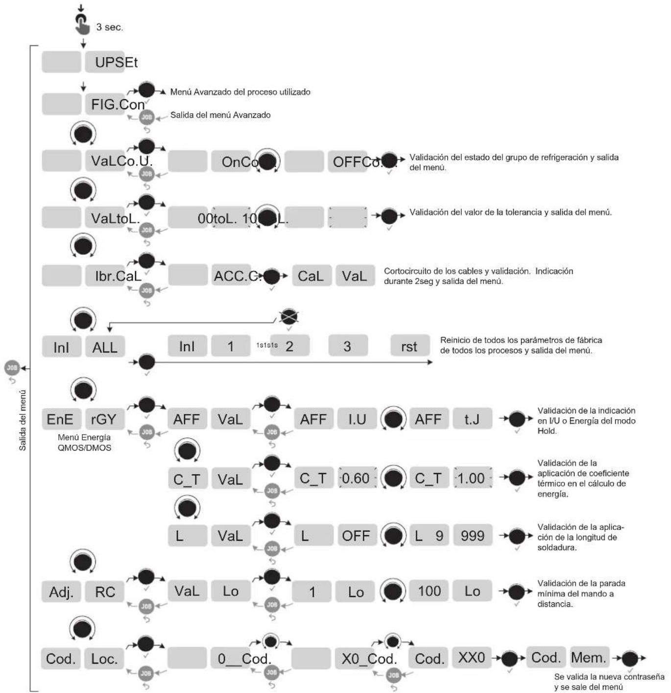
ACCESS TO SETUP MENU
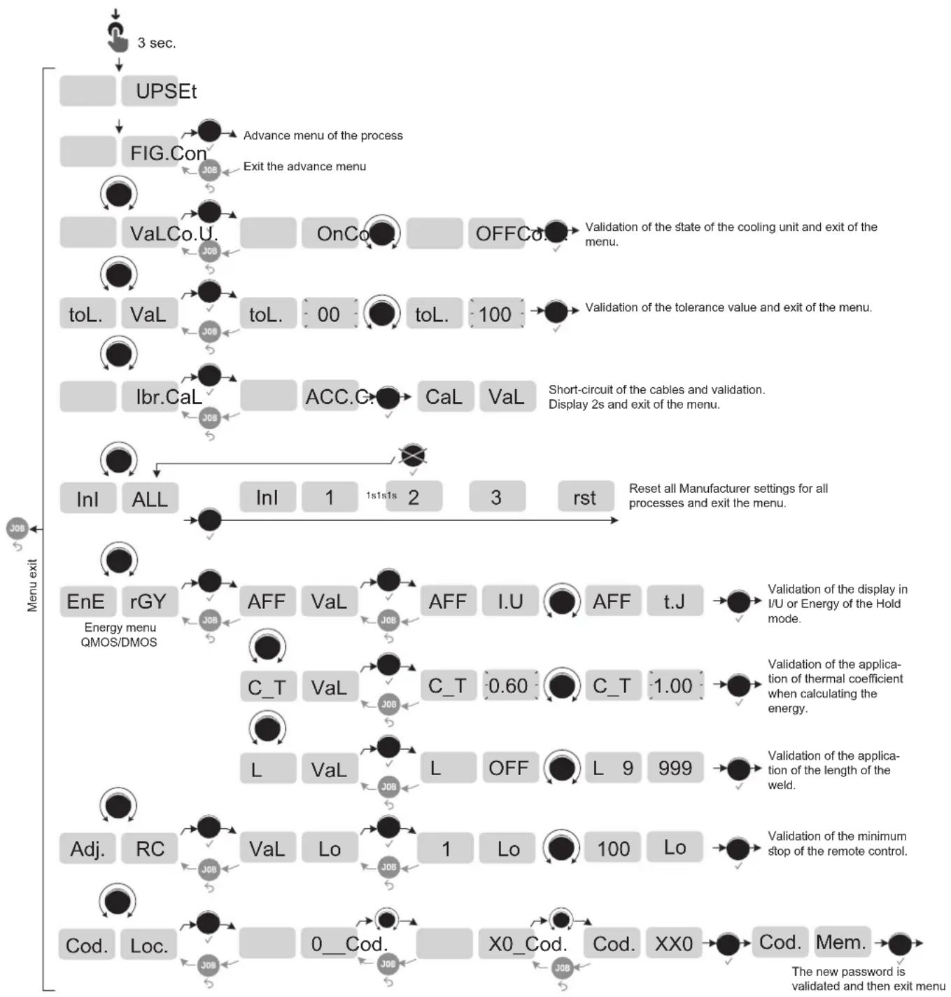
flowchart
graph TD
    A["3 sec."] --> B["UPSEt"]
    B --> C["FIG.Con"]
    C --> D["Advance menu of the process"]
    D --> E["Exit the advance menu"]
    E --> F["VaLCo.U."]
    F --> G["OnCo"]
    G --> H["OFFCo"]
    H --> I["Validation of the state of the cooling unit and exit of the menu."]
    I --> J["toL. VaL"]
    J --> K["toL. 00"]
    K --> L["toL. 100"]
    L --> M["Validation of the tolerance value and exit of the menu."]
    M --> N["Ibr.CaL"]
    N --> O["ACC.G."]
    O --> P["CaL VaL"]
    P --> Q["Short-circuit of the cables and validation. Display 2s and exit of the menu."]
    Q --> R["Inl ALL"]
    R --> S["Inl 1 1s1s1s 2 3 rst"]
    S --> T["Reset all Manufacturer settings for all processes and exit the menu."]
    U["Menu exit"] --> V["EnE rGY Energy menu QMOS/DMOS"]
    V --> W["AFF VaL"]
    W --> X["AFF I.U"]
    X --> Y["Validation of the display in I/U or Energy of the Hold mode."]
    V --> Z["C_T VaL"]
    Z --> AA["C_T 0.60"]
    AA --> AB["C_T 1.00"]
    V --> AC["L VaL"]
    AC --> AD["L OFF"]
    AD --> AE["L 9 999"]
    V --> AF["Adj. RC"]
    AF --> AG["Val Lo"]
    AG --> AH["1 Lo 100 Lo"]
    V --> AI["Cod. Loc."]
    AI --> AJ["X0_Cod. Cod. XX0"]
    AJ --> AK["Cod. Mem. The new password is validated and then exit menu"]
Advanced menu: MMA Standard or Pulse
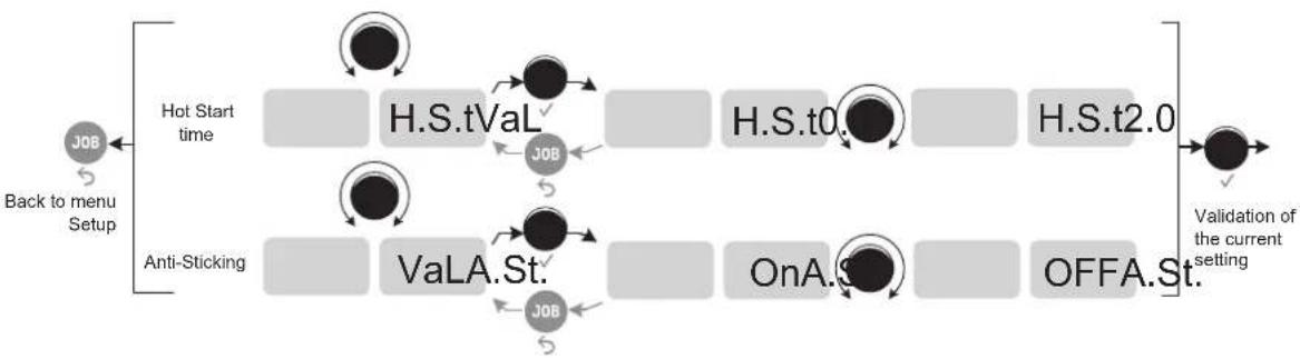
flowchart
graph LR
    A["Back to menu Setup"] --> B["Hot Start time"]
    B --> C["H.S.tVaL"]
    C --> D["H.S.t0."]
    D --> E["H.S.t2.0"]
    E --> F["Validation of the current setting"]
    G["Anti-Sticking"] --> H["VaLA.St."]
    H --> I["OnA. St."]
    I --> J["OFFA.St."]
    J --> F
Advanced menu: TIG Standard, Pulse, (Multi) Spot and (Multi) Tack
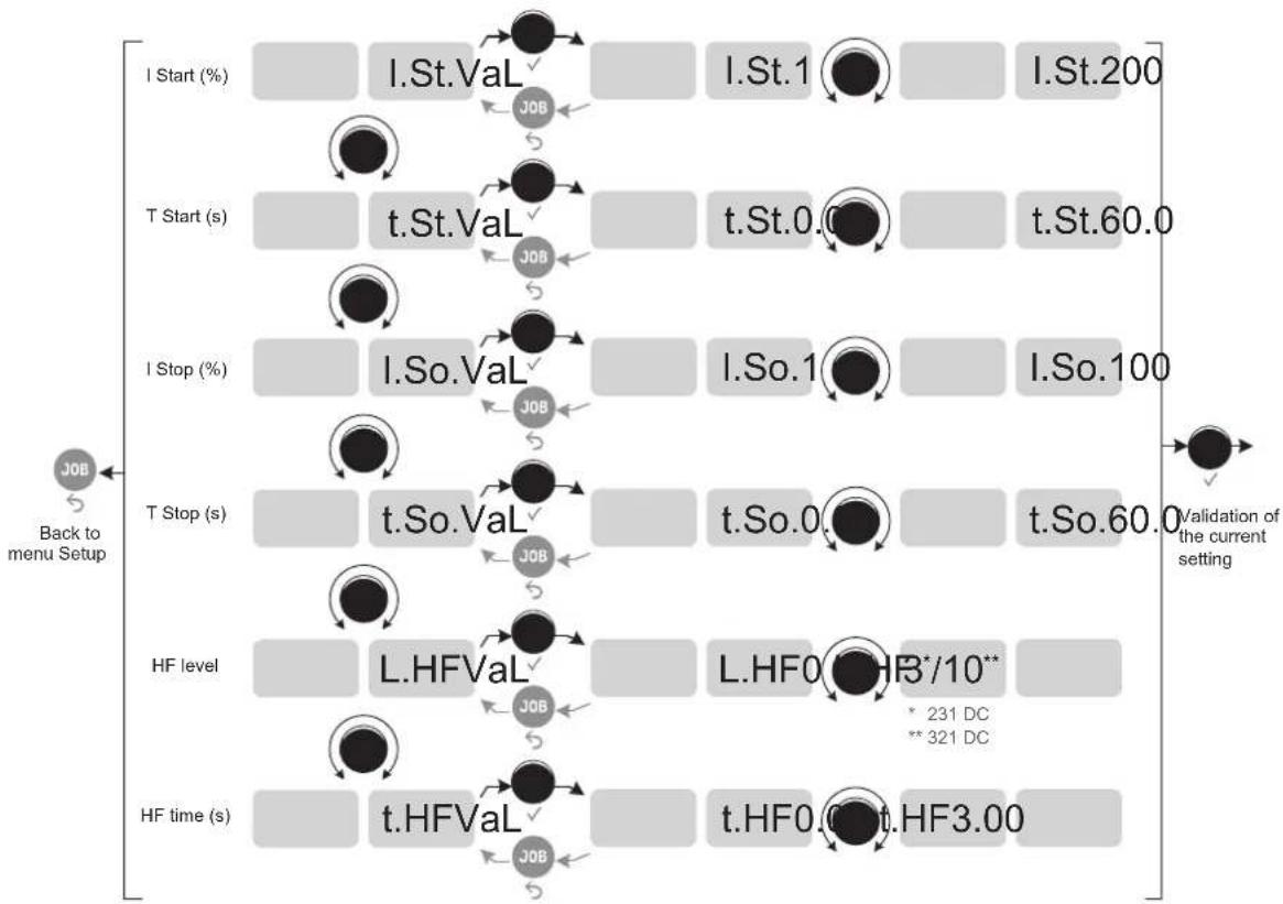
flowchart
graph TD
    A["I Start (%)"] --> B["I.St.Val"]
    B --> C["I.St.1"]
    C --> D["I.St.200"]
    E["T Start (s)"] --> F["t.St.Val"]
    F --> G["t.St.0.0"]
    G --> H["t.St.60.0"]
    I["I Stop (%)"] --> J["I.So.Val"]
    J --> K["I.So.1"]
    K --> L["I.So.100"]
    M["T Stop (s)"] --> N["t.So.Val"]
    N --> O["t.So.0"]
    O --> P["t.So.60.0"]
    Q["HF level"] --> R["L.HFVal"]
    R --> S["L.HF0*HR*/10** * 231 DC ** 321 DC"]
    T["HF time (s)"] --> U["t.HFVal"]
    U --> V["t.HF0.0t.HF3.00"]
    W["Back to menu Setup"] --> X["JOB"]
    X --> Y["JOB"]
    Y --> Z["JOB"]
    Z --> AA["JOB"]
    AA --> AB["JOB"]
    AB --> AC["JOB"]
    AC --> AD["JOB"]
    AD --> AE["Validation of the current setting"]
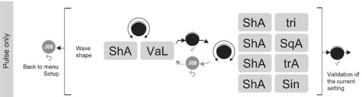
flowchart
graph LR
    A["Pulse only"] --> B["Back to menu Setup"]
    B --> C["Wave shape"]
    C --> D["ShA"]
    C --> E["VaL"]
    D --> F["ShA"]
    E --> G["Job"]
    F --> H["Validation of the current setting"]
    G --> H
    style A fill:#f9f,stroke:#333
    style H fill:#ccf,stroke:#333
OPTIONAL COOLING UNIT
| Reference | Product Name | Cooling power | Capacity | Power supply voltage |
| 070820 | KOOLWELD 1 | 1,000 W | 3 L | 24 V DC |
The cooling unit is automatically detected by the machine.
In the menu SEt UP → ●→ Con FIG. → ●
Co.U. On : the cooling unit is always running.
Co.U. OFF : the cooling unit can be deactivated in TIG mode.
Co.U. Auto : activation of the cooling unit during welding and deactivation 10 minutes after the end of welding.
The safety features supported by the cooling unit, to ensure the protection of the user and the torch, are as follows:
• Minimum coolant level.
- Minimum flow rate of coolant flowing through the torch.
• Thermal protection of the coolant.
Make sure that the cooling unit is switched off before disconnecting the inlet and outlet hoses for torch liquid. Coolant is harmful and irritates the eyes, mucous membranes and skin. Hot liquid may cause burns.
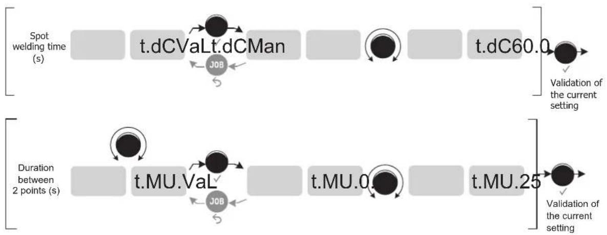
CALIBRATION
This mode is dedicated to the calibration of the welding accessories such as the torch, or earth clamp and cable.
The purpose of calibration is to compensate for variations in accessory lengths, so as to adjust the displayed voltage measurement and improve the energy calculation.
Access to calibration is done in the menu SEt UP → CaL Ibr.
The first step C.C. ACC. requires short-circuiting the accessories. In TIG, it is recommended that the short circuit be made between the collet holder and the ground clamp or directly on the workpiece. Once the short circuit has been made, confirm with the thumbwheel.
The second stage begins, and a progress bar CaL. III is displayed on the HMI of the power source. Pressing a button on the torch initiates the flow of the calibration current.
If the procedure was successful, the machine exits calibration mode automatically, along with a brief overview of the resistance value of the accessory. This value is now reflected in the voltage display and the energy calculation.
If unsuccessful, the menu exits automatically and displays a long CaL. no . If the operation fails, the circuit was not done correctly and the calibration must be redone.
DISPLAY CURRENT/VOLTAGE DURING WELDING
During welding, the machine measures and displays the welding current and voltage.
After the weld, the average current and voltage values or the energy and duration of the welding bead are displayed until the interface (buttons or scrollwheel) are touched, if the weld resumes or that a trigger press is not carried out.
Access to the current / voltage or energy / time configuration is available through the menu SEt UP → EnE rGY AFF
ENERGY MODE
This mode (which was developed for welding with DMOS-supported energy control) allows, in addition to the energy display of the weld bead post-welding, to set :
- The thermal coefficient C_T according to the standard used: 1 for ASME standards and 0.6 (TIG) or 0.8 (MMA) for European standards. The energy displayed is calculated taking into account this coefficient.
- Length of the weld bead L (OFF - mm): if a bead length is registered, then the energy display changes from joules, to joules/mm (the unit in the display «J» flashes).
TROUBLESHOOTING
This device has a fault monitoring system. In the event of a problem, error messages may be displayed.
If the user needs to open the product, they must turn off the power supply by disconnecting the electrical plug from the socket, and wait two minutes for safety.
If an error code which is not listed appears or your problems persist, contact your distributor.
| Error code Meaning CAUSES SOLUTIONS | |||
| Thermal protection | Maximum duty cycle reached. Obstructed air input. | • Wait for the light to go out before continuing the weld.• Pay attention to the duty cycle and make sure the air flows. | |
| US1 | A power surge has been detected. | The product has gone into a protective mode. | Check the wiring of the power outlet and the tightness of the terminals.If the overvoltage is only temporary, the product will resume operation after 15 seconds. |
| US2 | An undervoltage has been detected. | ||
| US3 | A phase of the electricity network is missing | ||
| Err USc | The trigger of the torch is at fault but still active. | The trigger of the torch is defective. | Remove the torch and check if the message is still accurate.If so, torch fault.If not, check the internal connections. |
| Err HAD | A defect on the VRD was found. - Contact your distributor. | ||
| Err HAP | A hard fault is detected. | A problem has been detected on the DSP or on the thermal disconnection of the SAM robotic module. | Check the wiring. |
| Err Ebp | A button on the keypad is defective. | A button on the keypad is short-circuited. | Replace the keypad. |
| CU 001 | A problem with the presence of the cooling unit is detected. | The cooling unit was detected by the product, but then the information was lost. | Check the connections between the cooling unit and the product (connector properly fitted and plugs securely mounted...). |
| CU 002 | A liquid flow problem has been detected. | The pump does not start (no sound). | Check the connections between the cooling unit and the product (connector properly fitted and plugs securely mounted...). |
| The pump is out-of-order and must be replaced. | |||
| The electronic control board inside the cooling unit is out of order and needs to be replaced. | |||
| The pump works (noise) but there is no liquid circulation. | The pump is not primed, perform a forced priming procedure by putting a hose or a torch directly between the water outlet (blue) and the container spout. | ||
| The coolant circuit is blocked, the torch is out of order. | |||
| Check the connections between the cooling unit and the product (connector properly fitted and plugs securely mounted...). | |||
| The flow sensor is defective and must be replaced. | |||
| The electronic control board inside the cooling unit is out of order and needs to be replaced. | |||
| CU 003 | A coolant level problem is detected. There is no coolant in the tank. | Check the coolant level and top up to the MAX level indicated on the product. | |
| Check the connection between the coolant level sensor and the control board inside the cooling unit. | |||
WARRANTY CONDITIONS
The warranty covers any defects or manufacturing faults for two years from the date of purchase (parts and labour).
The warranty does not cover:
- Any other damage caused during transport.
- The general wear and tear of parts (i.e.: cables, clamps, etc.).
- Incidents caused by misuse (incorrect power supply, dropping or dismantling).
- Environment-related faults (such as pollution, rust and dust).
In the event of a defect, return the equipment to your distributor, enclosing:
- dated proof of purchase (receipt, invoice, etc.),
- a note explaining the malfunction.
text_image
VWO I CWeld A S % Std V Hz kJ SETUP PRESS 3" S / JOBtext_image
NIL. 5Pt A S % SETUP PRESS 3" Multi S / JOBtext_image
PRE I % I % t Hz A S % EAC V Hz kJ SETUP PRESS 3' S / JOBtext_image
VRO I % I Cweld E. A s % On V Hz kJ SETUP PRESS 3" S / JOBtext_image
P DB L 1 5 2 4 2 3 L torch P torch DB torch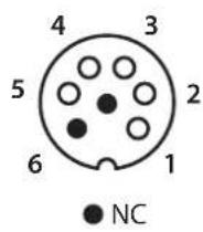
text_image
3 DB torch 4 L torch 2 2 5 1 DB + P torchtext_image
VRD I % I % B Hz A s % Std V Hz kJ SETUP PRESS 3' S / JOBtext_image
VRD I % I % t Hz A s % PL5 V Hz kJ SETUP PRESS 3' S / JOBtext_image
V60 I EWeld A s % Std V Hz kJ SETUP PRESS 3" S / JOBtext_image
VOUT I % I % t Hz A s % PLS V Hz kJ SETUP PRESS 31 S / JOBtext_image
I V A s % SPL V Hz kJ SETUP PRESS 3" J08text_image
NIL. A s % SPt V Hz kJ SETUP Press 9" Multi S / JOBtext_image
I % I % t Hz A S % EAC V Hz kJ SETUP PRESS 3" S / JOBtext_image
I % I % t Hz NULL. A s EAC V Hz kJ SETUP PRESS 5° Multi JOBtext_image
2mm 5mm 10mmflowchart
graph TD
    A["Start"] --> B["T1"]
    B --> C["T2"]
    C --> D["T3"]
    D --> E["T4"]
    F[">0.5s<0.5s<0.5s"] --> G["Arrow to top of F"]
    H["Arrow to right"] --> I["Arrow to right"]
    J["Arrow to left"] --> K["Arrow to left"]
    L["Arrow to right"] --> M["Arrow to right"]
    N["Arrow to left"] --> O["Arrow to left"]
    P["Arrow to right"] --> Q["Arrow to right"]
    R["Arrow to left"] --> S["Arrow to right"]
    T["Arrow to right"] --> U["Arrow to right"]
    V["Arrow to left"] --> W["Arrow to right"]
    X["Arrow to right"] --> Y["Arrow to right"]
    Z["Arrow to left"] --> AA["Arrow to right"]
    AB["Arrow to right"] --> AC["Arrow to right"]
text_image
P DB L 1 5 2 4 2 3 L torch P torch DB torch

text_image
3 DB torch 4 L torch 2 2 5 1 DB + P torchtext_image
VRD I CWM A s % Std V Hz kJ SETUP PRESS 3° S / JOBtext_image
VRD I % I % t Hz A s % PL5 V Hz kJ SETUP PRESS 3° / JOBACCESO AL MENÚ SETUP
SEt UP → ●→ CaL Ibr.
WAARSCHUWINGEN - VEILIGHEIDSINSTRUCTIES
ALGEMENE INSTRUCTIES
INSTALLATIE - WERKING VAN HET APPARAAT
text_image
VAC I EWeld A s % Std V Hz kJ SETUP PRESS 8" S / JOBtext_image
VOUT I % I % t Hz A s % PLS V Hz kJ SETUP PRESS-T S / JOBtext_image
VBD I GAMU A s % SPt V Hz kJ SETUP PRESS 3" S / JOBtext_image
VAG I Cath A S % NULL. SPt V Hz kJ SETUP PRESS 9" S / JOBtext_image
I % I % t Hz A s % EAC V Hz kJ SETUP PRESS 9" S / JOBtext_image
E. A S % On V Hz kJ SETUP PRESS 3° S / JOBtext_image
Bouton principal T1 T2text_image
P L DB 1 5 2 P torch 4 L torch 3 DB torch

text_image
3 DB torch 4 L torch 2 2 5 1 DB + P torchMMA (SMAW) LASMODULE
AANSLUITING EN ADVIEZEN
text_image
VRD I % 2 % 4 Hz A s % Std V Hz kJ SETUP PRESS 3° S / JOBtext_image
VRD I % I % t Hz A s % PL5 V Hz kJ SETUP PRESS 3° JOBtext_image
Exploded view diagram of electronic components with numbered parts for identificationtext_image
Exploded view diagram of an electronic device with numbered components for identification| 1 Embase Texas / Texas plug 51528 | |
| 2 Clavier TIG / TIG keypad 51996 | |
| 3 Circuit IHM / HMI circuit E0109C | |
| 4 Transformateur HF / HF transformer 63818 | |
| 5 Circuit fond de panier / Backplane circuit E0106C | |
| 6 Circuit microcontrôleur / Microcontroller circuit E0107C | |
| 7 Circuit HF/ HF circuit E0204C | |
| 8 Circuit alimentation auxiliaire / Auxiliary power supply circuit E0113C | |
| 9 Electrovanne 2 voies / 2-way solenoid valve 70991 | |
| 10 Interrupteur triphasé / Three-phase switch 51062 | |
| 11 Circuit connecteur groupe froid / Cooling unit connector circuit | E0111C |
| 12 Ventilateur / Fan | 50999 |
| 13 Circuit Primaire / Primary circuit | E0110C |
| 14 Module pont de diode / Diode bridge module | 52196 |
| 15 Module IGBT / IGBT module | 52203 |
| 16 Diode rapide 2X120A / Fast diode 2X120A | 52197 |
| 17 Capteur de courant / Current sensor | 64463 |
| 18 Transformateur torique / Toroidal transformer | 63816 |
| 19 Self de mode commun / Common mode self | 63601 |
INTERRUPTEUR VRD / VRD SWITCH / VRD-EIN-AUS-SCHALTER / INTERRUPTOR VRD / VRD SCHAKELAAR / INTERRUTTORE VRD
231 DC FV
natural_image
Technical diagram of an electronic device showing internal components and a separate panel (no text or labels visible)
natural_image
Technical diagram of an electrical enclosure with a magnified inset showing internal components (no text or labels)321 DC TRI
natural_image
Technical illustration of an electronic device with internal components and a separate panel (no text or symbols visible)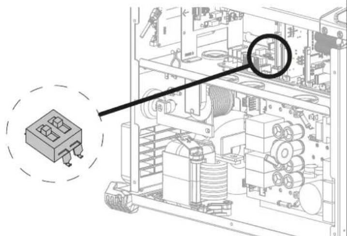
text_image
Technical diagram of an electronic device with labeled components and a magnified inset showing a component with ports and coils.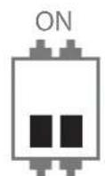
VRD OFF VRD ON
CIRCUIT DIAGRAM / SCHALTPLAN / DIAGRAMA ELECTRICO / ЭЛЕКТРИЧЕСКАЯ СХЕМА / ELEKTRISCHE SCHEMA / SCEMA ELETTRICO
231 DC FV

text_image
Electrical circuit diagram with labeled components including resistors, capacitors, relays, and switches321 DC TRI
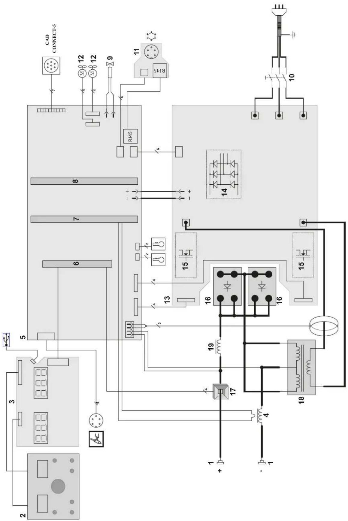
text_image
Electrical schematic diagram with labeled components and connections, including CAD CONNECT-5, R45, and various electronic devices and meters.TECHNICAL SPECIFICATIONS / TECHNISCHE DATEN / ESPECIFICACIONES TÉCNICAS / ТЕХНИЧЕСКИЕ СПЕЦИФИКАЦИИ / TECHNISCHE GEGEVENS / SPECIFICHE TECNICHE
| Primaire / Primary / Primär / Primario / Первичка / Primaire / Primario 231 DC FV | ||||||
| Tension d'alimentation / Power supply voltage / Versorgungsspannung / Tensión de red eléctrica / Напряжение питания / Voedingsspanning / Tensione di alimentazione U1 | 110 V +/- 15% 230 V +/- 15% | |||||
| Fréquence secteur / Mains frequency / Netzfrequenz / Fracuencia / Частота сети / Frequentie sector / Frequenza sattore | 50 / 60 Hz | |||||
| Nombre de phases / Number of phases / Anzahl der Phasen / Número de fases / Количество фаз / Aantal fasen / Numero di fase | 1 | |||||
| Fusible disjoncteur / Fuse / Sicherung / Fusible disyuntor / Плавкий предохранитель прерывателя / Zekering hoofdschakelaar / Fusibile disgiuntore | 32 A 16 A 32 A | |||||
| Courant d'alimentation effectif maximal / Maximum effective supply current / Corriente de alimentación efectiva máxima / Maximale effective voedingsstroom / Corrente di alimentazione effettiva massima / Maksymalny efektywny prąd zasiliania | 11eff 20 A 16 A 20 A | |||||
| Courant d'alimentation maximal / Maximum supply current / Corriente da alimentación máxima / Maximale voedingsstroom / Corrente di alimentazione massima / Maksymalny prąd zasiliania | 11max 35 A 37 A 37 A | |||||
| Section du cordon secteur / Mains cable section / Sectile netsnoer / Sección del cable de alimentación / Sezione del cavo di alimentazione / Odcinek przewodu zasillajepego | 3 × 2.5 mm^2 | |||||
| Puissance active maximale consommée / Maximum active power consumed / Consumo máximo de energía activa / Maximale actieve verbruikte vermogen / Potenza attiva massima consumata / Maksymalny pobór mocy czynne | 8300 W | |||||
| Consommation au ralenti / Idle consumption / Consumo en ralentizado / Stationair verbruik / Consumo al minimo / Zużycie na biegu jialowym | 14 W | |||||
| Rendement à l2max / Efficiency at l2max / Eficiencia a l2máx / Rendement bij l2max / Efficienza a l2max / Sprawność przy l2max | 81.7 % | |||||
| Facteur de puissance à l2max / Power factor at l2max / Factor de potencia à l2max / Inschakelduur bij l2max / Ciclo di potenza à l2max / Współczynnik mocy przy l2max | λ 0.994 | |||||
| Classe CEM / EMC class / Classe CEM / Klasse CEM / Classe CEM / Klasa EMC A | ||||||
| Secondaire / Secondary / Sekundár / Secundario / Вторичка / Secondair / Secondario | MMA TIG MMA TIG | MMA | TIG | |||
| Tension à vide / No load voltage / Leerlaufspannung / Tensión al vacio / Напряжение холостого хода / Nullastspanning / Tensione a vuoto (TCO) | 68 V | 77.8 V | ||||
| Tension à vide réduite (Tension VRD) / Reduced open circuit voltage (VRD voltage) / Tensión reducida en vacio (tensión VRD) / Nullast spanning (Spanning VRD) / Tensione a vuoto ridotta (Tensione VRD) / Obniżone napięcie biego jalowego (Napięcie VRD) | Ur 31 V | |||||
| Nature du courant de soudage / Type of welding current / Tipo de corriente de soldadura / Type lasstroom / Tipo di corrente di saldatura / Rodzaj prądu spawania | DC | |||||
| Modes de soudage / Welding modes / Modos de soldadura / Lasmodules / Modalità di saldatura / Tryby spawania | MMA, TIG | |||||
| Tension créte du dispositif d'amortgage manuel (EN60974-3) / Manual striking system's maximum voltage (EN60974-3) / Spitzenspannung des manuellen Starterérées (EN60974-3) / Tensión pico del dispositivo de cebado manual (EN60974-3) / Пиковое напряжение механизма ручного поджига (EN60974-3) / Piekspanning van het handmatige startysteem (EN60974-3) / Tensione di picco del dispositivo di innesco manuale (EN60974-3) / Napięcie szczytowe urządzenia do rozruchu ręcznego (EN60974-3) | 12.6 kV | |||||
| Courant de soudage minimal / Minimum welding current / Corriente minima de soldadura / Minimale lasstroom / Corrente minima di saldatura / Minimalny prąd spawania | 3 A | |||||
| Courant de sortie nominal / Rate current output / nominaler Arbeitsstrom / Corriente de salida nominal / Номинальный выходной ток / Nominale uitgangsstroom / Corrente di uscita nominale | 12 | 5 → 120 A | 3 → 140 A | 5 → 230 A | 3 → 230 A | 3 → 230 A |
| Tension de sortie conventionnelle / Conventional voltage output / entsprechende Arbeitsspannung / Условное выходные напряжения / Tensión de salida convencional / Conventionele uitgangsspanning / Tensione di uscita convenzionale | U2 | 20.2 → 24.8 V | 10.1 → 15.6 V | 20.2 → 29.2 V | 10.1 → 19.2 V | 10.1 → 19.2 V |
| Facteur de marche à 40°C (10 min), Norme EN60974-1 / Duty cycle at 40°C (10 min), Standard EN60974-1. Einschaldauer @ 40°C (10 min), EN60974-1-Norm / Ciclo de trabajo a 40°C (10 min), Norma EN60974-1/ ПВ% при 40°C (10 мин), Норма EN60974-1. / Inschakelduur bij 40°C (10 min), Norm EN60974-1, Ciclo di lavoro a 40°C (10 min), Norma EN60974-1. | Imax | 23 % | 40 % | 19 % | 45 % | 25 % |
| 60 % | 85 A | 120 A | 145 A | 200 A | 175 A | |
| 100 % | 70 A | 100 A | 120 A | 160 A | 145 A | |
| Pression maximale de gaz / Maximum gas pressure / Maximaler Gasdruck / Presión máxima del gas / Максимальное давление газа / Maximala gasdruk / Pressione massima del gas | Pmax | 0.5 MPa (5 bars) | ||||
| Température de fonctionnement / Functionning temperature / Betriebstemperatur / Temperatura de funcionamiento / Рабочая температура / Gebruikstemperatuur / Temperatura di funzionamento | -10°C → +40°C | |||||
| Température de stockage / Storage temperature / Lagertemperatur / Temperatura de almacenaje / Температура хранения / Bewaartemperatuur / Temperatura di stoccaggio | -20°C → +55°C | |||||
| Degré de protection / Protection level / Schutzart / Grado de protección / Степень защиты / Beschermingsklasse / Grado di protezione | IP23S | |||||
| Classe d'isolation minimale dos enroulements / Minimum coil insulation class / Clase mínima da aislamiento del bobinado / Minimale isolatisklasse omwikkelingen / Classe minima di isolamento degli avvolgimenti / Minimalna klasa izolacji okablowania | B | |||||
| Dimensions (Lxlxh) / Dimensions (LxWxH) / Abmessungen (Lxbxt) / Dimensiones (Lxlxh) / Размеры (ДхШхВ) / Almetingen (Lxlxh) / Dimensioni (Lxlxh) | 49 x 26 x 40 cm | |||||
| Poids / Weight / Gewicht / Bec / Peso / Gewicht / Peso | 16.5 kg | |||||
*Les facteurs de marche sont réalisés selon la norme EN60974-1 à 40°C et sur un cycle de 10 min. Lors d'utilisation intensive (supérieur au facteur de marche) la protection thermique peut s'enclencher, dans ce cas, l'arc s'éteint et le témoin s'allume. Laissez l'appareil alimenté pour permettre son refroidissement jusqu'à annulation de la protection. La source de courant décrit une caractéristique de sortie de type tombante. Dans certains pays, UO est appelé TCO.
*The duty cycles are measured according to standard EN63974-1 à 40°C and on a 10 min cycle. While under intensive use (> to duty cycle) the thermal protection can turn on, in that case, the arc switches off and the indicator switches on. Keep the machine's power supply on to enable cooling until thermal protection cancellation. The welding power source describes an external drooping characteristic. In some countries, UO is called TCO.
* Einschaltdauer gemäß EN80574-1 (10 Minuten - 40°C). Bei sehr intensivem Gebrauch (Einschaltdauer) kann der Thermoschulz ausgelöst werden. In diesem Fall wird der Lichtbogen abgeschaltet und die entsprechende Warnung erscheint auf der Anzeige. Das Gerät zum Akühlen nicht ausschallen und laufen lassen bis das Gerät weder benefit. Das Gerät entspricht in seiner Charakteristik einer Spannungsquelle mit fallender Kernlinis. In einigen Ländern wird U0 als TCO bezeichnet.
*Los ciclos de trabajo están realizados en acuerdo con la norma EN60974-1 a 40°C y sobre un ciclo de diez minutos. Durante un uso intensivo (superior al ciclo de trabajo), se puede activar la protección térmica. En este caso, el arco se apaga y el indicador | ¡se enciende. Deje el aparato conectado para permitir que se entfrie hasta que se anule la protección. La fuente de corrente de soldadura posee una salida de tipo corriente constante. En algunos países, UO se llama TCC.