
MFLD1 - Wall mount SANUS - Free user manual and instructions
Find the device manual for free MFLD1 SANUS in PDF.

User questions about MFLD1 SANUS
0 question about this device. Answer the ones you know or ask your own.
Ask a new question about this device
Download the instructions for your Wall mount in PDF format for free! Find your manual MFLD1 - SANUS and take your electronic device back in hand. On this page are published all the documents necessary for the use of your device. MFLD1 by SANUS.
USER MANUAL MFLD1 SANUS
MFLD1-B2
Drywall TV Mount
Compatible with Amazon Fire TV smart TVs Instruction Manual
| ES | Texto en español, página 24 |
| FR | Texte français page 27 |
| DE | Deutscher Text Seiten 30 |
| PT | Português 33 |
| IT | Italiano 36 |
| JA | 日本語は39ページ |
natural_image
Technical line drawing of a mechanical component with mounting holes and internal features (no text or symbols)
IMPORTANT SAFETY INSTRUCTIONS. READ ENTIRE MANUAL PRIOR TO USE. SAVE These INSTRUCTIONS
1
TV (PLUS ACCESSORIES)
WEIGHT LIMIT
DO NOT EXCEED
If your TV weighs more,
this mount is NOT
compatible.
Visit SANUS.com to find
a compatible mount.
2
ACCEPTABLE
WALL TYPES
Drywall
CAUTION:
Drywall covering must be
3/8 in. (9.5 mm) or greater.

Wood studs
Perfect! Perf
Solid concrete or concrete block
Perfect!

Unsure?
Contact Customer Service
(see back page)
3
GRAB YOUR TOOLS
Pencil
Drywall
Applications
NO DRILL OPTION
Hammer
Tape Measure
Wood Stud
Applications
Electric Drill
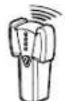
Stud Finder
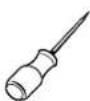
Awl

1/8 in. (3.2 mm)
Wood
Drill Bit

Phillips Screwdriver
Concrete
Applications
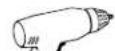
Electric Drill

Hammer
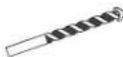
5/16 in. (8 mm)
Masonry
Drill Bit
4
MORE STUFF TO READ
Please read through these instructions completely to be sure you're comfortable with this easy install process. Also check your TV owner's manual to see if there are any special requirements for mounting your TV.
If you do not understand these instructions or have doubts about the safety of the installation, assembly or use of this product, contact Customer Service.

CAUTION: Avoid potential personal injuries and property damage!
● This product is designed for use with wood studs, solid concrete and concrete block walls, and drywall only.
- The wall must be capable of supporting five times the weight of the TV and mount combined.
- Do not use this product for any purpose not explicitly specified by manufacturer.
● Manufacturer is not responsible for damage or injury caused by incorrect assembly or use.
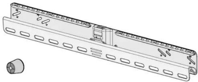
Parts Included
WARNING: This product contains small items that could be a choking hazard if swallowed. Before starting assembly, verify all parts are included and undamaged. If any parts are missing or damaged, do not return the damaged item to your dealer; contact Customer Service. Never use damaged parts!

NOTE: Not all hardware included will be used.
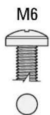
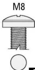
![STEP 1 01 TV Screws (qty. 2 each) [Only one size fits your TV] M4 M4 x 12mm M4 x 35mm M6 M6 x 12mm M6 x 20mm M6 x 35mm M8 M8 x 16mm M8 x 35mm M8 x 25mm M8 x 50mm 02 Washers M4 qty. 2 M6/M8 qty. 2 03 Spacers [If necessary] qty. 2qty. 4 qty. 2 04 TV Bracket qty.1](/content/2026/04/676532/images/8bad14eeb59ed9eb75c885290412cff098f176a69f99fdf8053f4dcc6003c707.jpg)
STEP 2
Washers
(Wood Screws)

qty.2
Wood
Screws

qty.2
(Wall Plate Screws)
For CONCRETE installations ONLY For DRYWALL inst

CAUTION: FOR STEP 2A ONLY:
Do not use in concrete or plaster & lath.
Nail

qty. 32
14 ga. × 1 ¼ in.

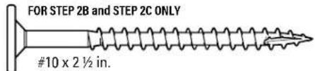
CAUTION: FOR STEP 2C ONLY:
Do not use in drywall or wood.
Concrete Anchors

qty.2
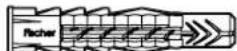
Fischer UX8 x 50R
STEP 3
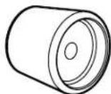
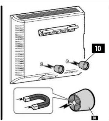
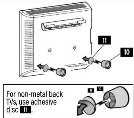
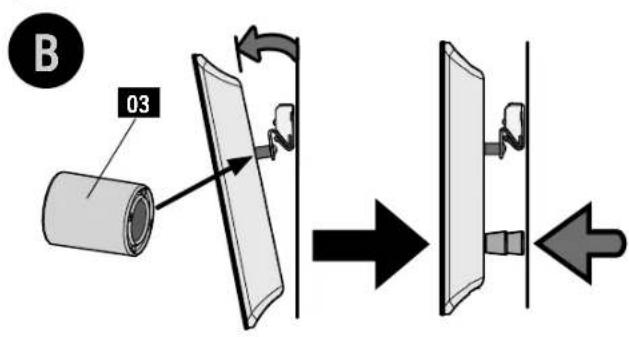
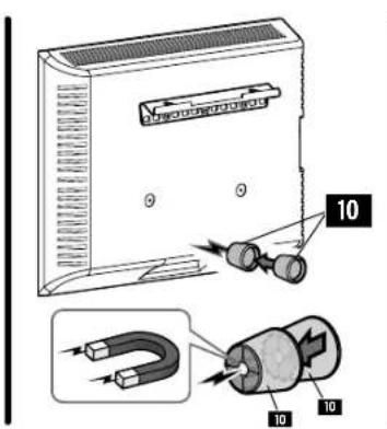
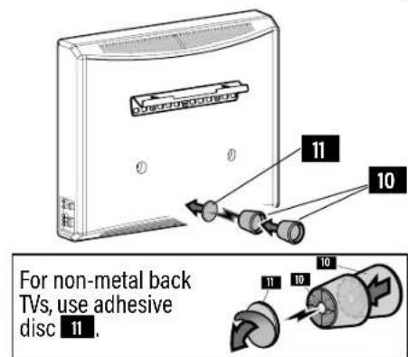
Standoff *
(Magnetic Leveling Feet)

qty.2
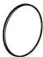
Disc
(Adhesive backed)

qty.2

WARNING: This product contains a magnet. The planted medical device such as a pacemaker plantable cardioverter defibrillator (ICD) is in magnetic fields may affect the operation of those s, resulting in serious injury or death. If you have planted medical device, keep at least 13 cm (5 in.) in your device and the magnet. Please consult your physician or medical professional prior to using this product.
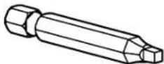
INCLUDED
Square Driver
Bit

qty.1
1
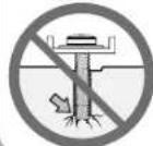
Attach TV Bracket to Your TV
1.1 Select TV Screw Diameter

NOTE: Only one screw size fits your TV.
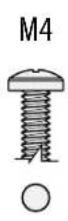
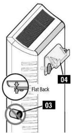
1.2 Determine TV Screw Length

- Flat Back TV
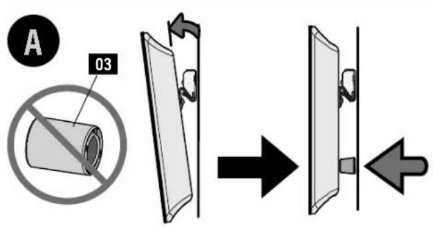
spacers 03 are not necessary.

- Rounded Back TV
- Flat Back TV With Extra Space Needed
[for cables or inset holes]
Use spacers 03 to create extra space between the TV and TV bracket.
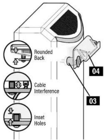
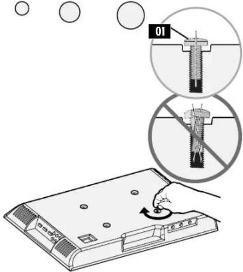
CAUTION:
Verify adequate thread engagement with your screw/washer/spacer combination AND TV Bracket 04
- Too short will not hold the TV.
- Too long will damage the TV.
▲ Too Short
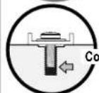
▲ Too Long
1.3 Attach the TV Bracket
2
Attach Wall Plate to Wall
Follow the corresponding step for your installation method.
IMPORTANT:
You must determine your wall construction to correctly secure the wall plate to the wall.
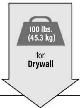
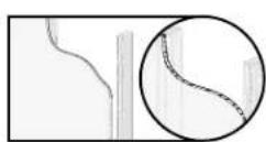
DRYWALL
[TVs up to 100 lbs. (45.3 kg)]
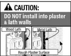
CAUTION:
DO NOT install into plaster & lath walls
STEP 2A
on PAGE 10
natural_image
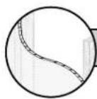
Circular diagram showing a curved line with vertical dashed lines, no text or symbols present⚠️ CAUTION: Avoid potential personal injuries and property damage!
● DO NOT mount to patched areas/drywall seams /uneven walls
- Drywall must be of sound construction with no water damage. If water damage ever occurs - remove the TV immediately
- Your TV MUST be centered on the wall plate
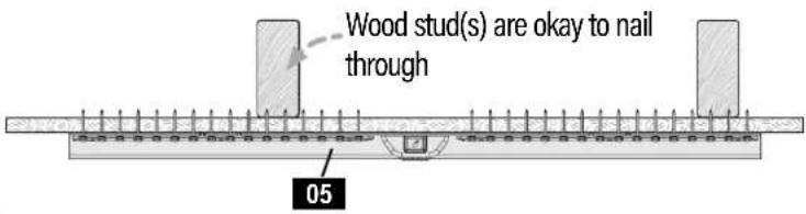
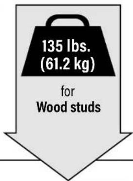
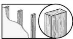
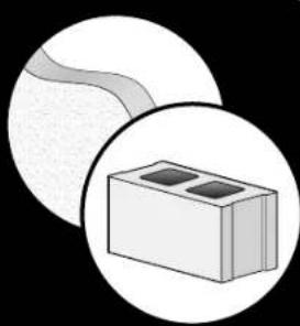
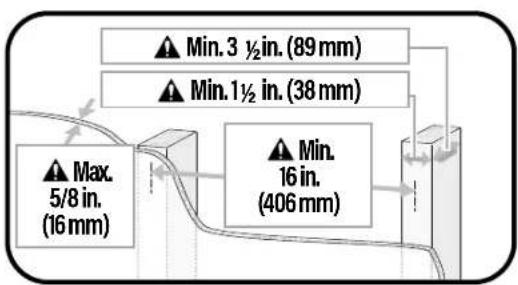
WOOD STUD
[TVs up to 135 lbs. (61.2 kg)]
natural_image
Simple line drawing of a wooden block with visible grain patterns (no text or symbols)STEP 2B
on PAGE 12
CAUTION: Avoid potential personal injuries and property damage!
Two stud centers must be located for proper installation.
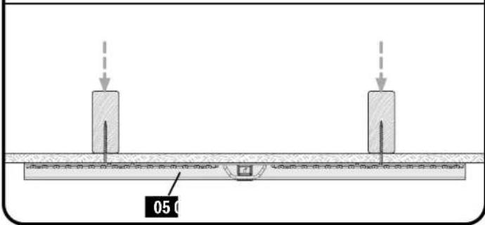
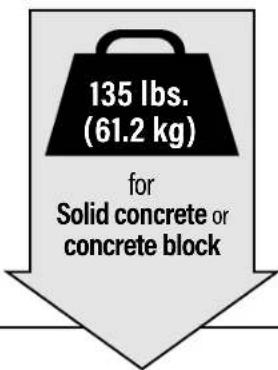
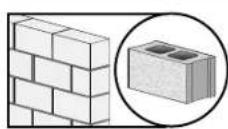
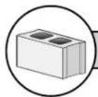
SOLID CONCRETE
and
CONCRETE BLOCK
[TVs up to 135 lbs. (61.2 kg)]
STEP 2c
on PAGE 14
natural_image
Illustration of a block with two square holes, enclosed in a circular frame (no text or symbols)CAUTION: Avoid potential personal injuries and property damage!
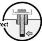
The mount must be installed directly onto the concrete surface (no surface covering).
natural_image
Diagram showing a beam under load with two vertical supports and an arrow indicating upward motion (no text or symbols)2A
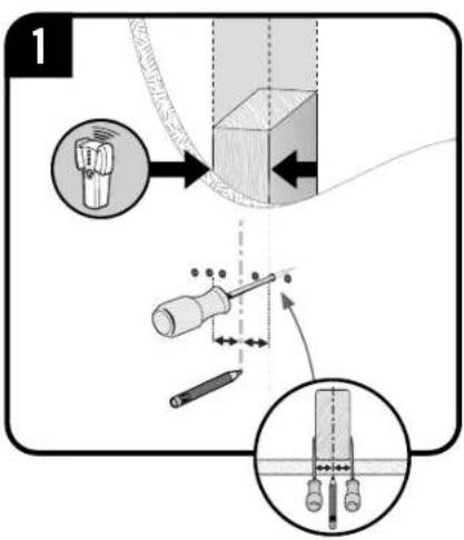
DRYWALL (only) INSTALLATION [TVs up to 100 lbs. (45.3 kg)]
2A.1 Verify Your Wall
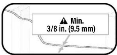
CAUTION: Avoid potential personal injuries and property damage!
- Drywall covering must be 3/8 in. (9.5 mm) or greater
- Drywall must be mounted on studs, no more than 24 in. (609 mm) on center, [minimum stud size: nominal 2 x 4 in. (51 x 102 mm) actual 1½ x 3½ in. (38 x 89 mm)]
- Drywall must be sound with no water damage. If water damage ever occurs — remove the TV immediately
- DO NOT mount to patched areas, on drywall seams or uneven walls
- Your TV MUST be installed centered on the wall plate
• DO NOT install into plaster & lath walls
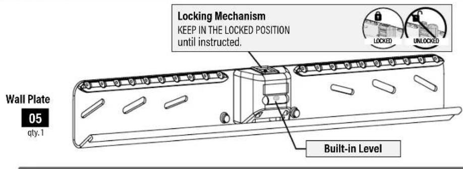
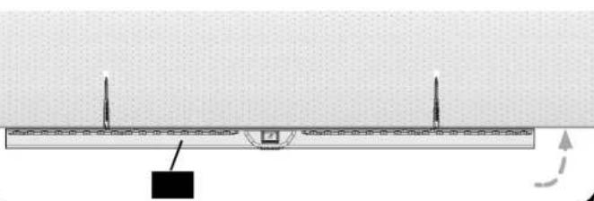
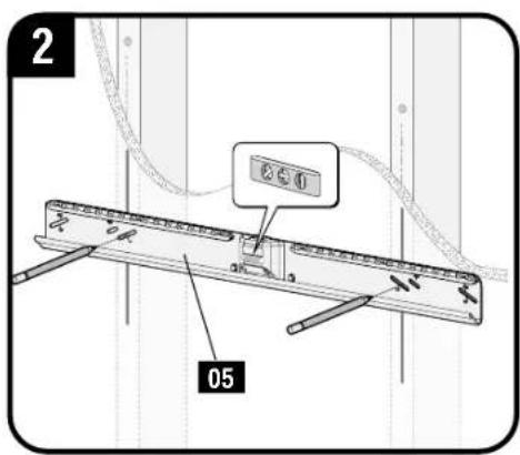
2A.2 Attach the Wall Plate
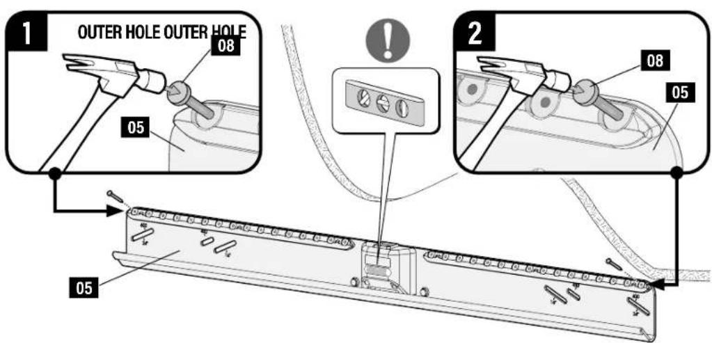
Position wall plate 05 on your wall, and secure a nail 08 in BOTH OUTER holes.
IMPORTANT: Wall plate 05 MUST be level when securing the second nail 08
CAUTION: Avoid potential personal injuries and property damage!
If ANY of the 32 nails 08 encounter excessive resistance (metal object) - STOP and call Customer Service.
DO NOT reuse nails 08 after removing. DO NOT use store-bought nails.
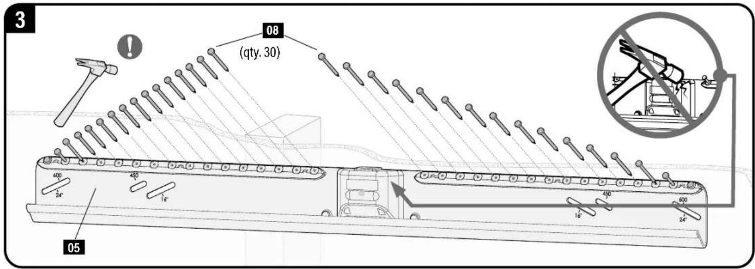
IMPORTANT: Alternate installing the remaining thirty (30) nails 08 from side to side.
CAUTION: Avoid potential personal injuries and property damage! Thirty-two (32) nails 08 total, must be used in wall plate 05.
Go to STEP 3 on PAGE 16.
2B
WOOD STUD INSTALLATION [TVs up to 135 lbs. (61.2 kg)]
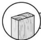
2B.1 Verify Your Wall
CAUTION: Avoid potential personal injuries and property damage!
• Drywall covering the wall must not exceed 5/8 in. (16 mm)
- Minimum wood stud size: nominal 2 x 4 in. (51x102 mm) actual 1½x3½in. (38x89 mm)
● Minimum horizontal space between fasteners: 16 in. (406 mm)
- Stud centers must be verified - not all walls have conventional 16 in. (406 mm) stud spacing
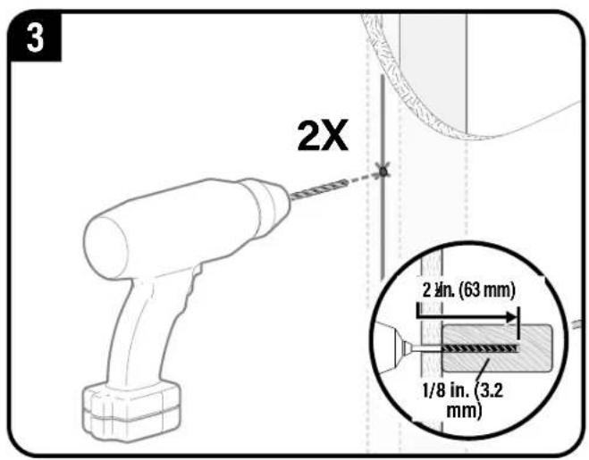
2B.2 Attach the Wall Plate
IMPORTANT: If you DO NOT have two studs that are 16 inches (406 mm) to 24 inches (609 mm) apart - OR - you cannot center wall plate 05 on your studs, follow STEP 2A on PAGE 10, for drywall installation.
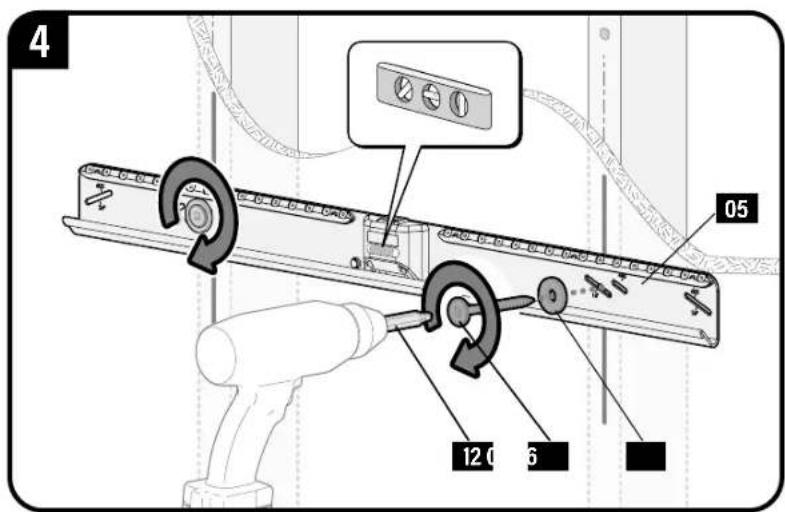
▲ CAUTION: Improper use could reduce the holding power of screws 07 DO NOT over-tighten the screws.
Go to STEP 3 on PAGE 16.
2c
SOLID CONCRETE/CONCRETE BLOCK INSTALLATION
[TVs up to 135 lbs. (61.3 kg)]
2C.1 Verify Your Wall
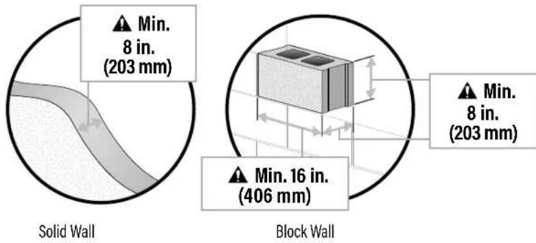
CAUTION: Avoid potential personal injuries and property damage!
● Minimum solid concrete thickness: 8 in. (203 mm)
● Minimum concrete block size: 8 x 8 x 16 in. (203 x 203 x 406 mm)
● Minimum horizontal space between fasteners: 16 in. (406 mm)
- Mount wall plate 05 directly onto the concrete surface (no wall covering)
2C.2 Attach the Wall Plate
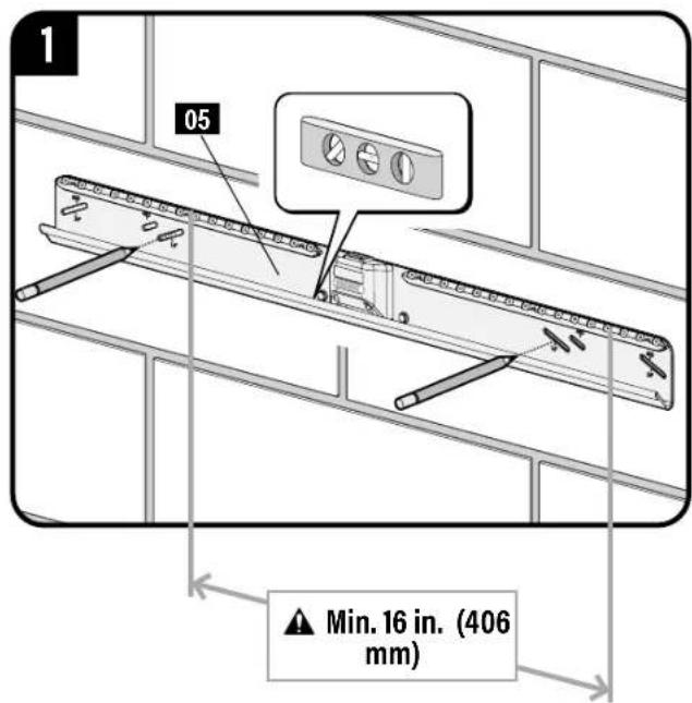
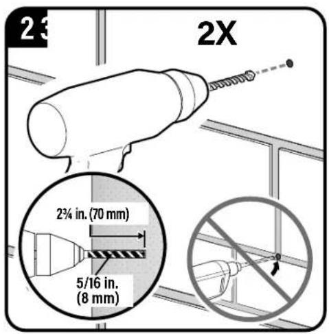
IMPORTANT: Never drill into the mortar between blocks.
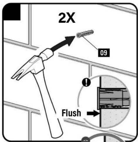
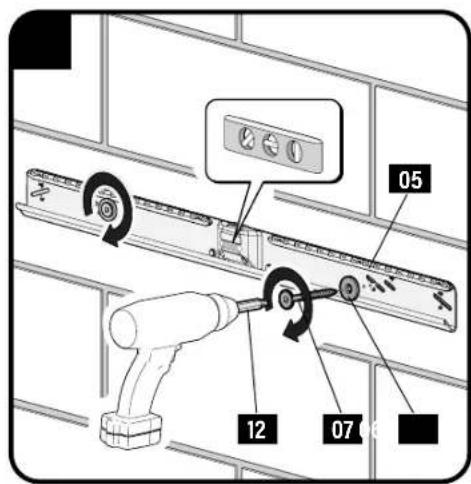
CAUTION: Improper use could reduce the holding power of screws 07. DO NOT over-tighten the screws.
3
HANG YOUR TV
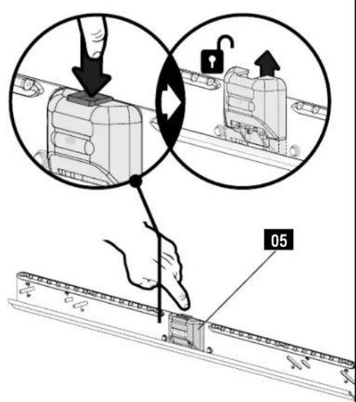
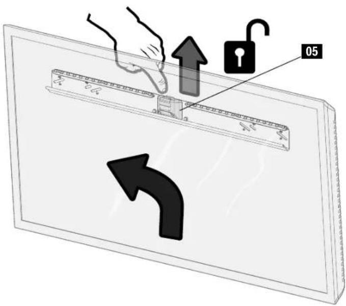
3.1 Unlock the Wall Plate
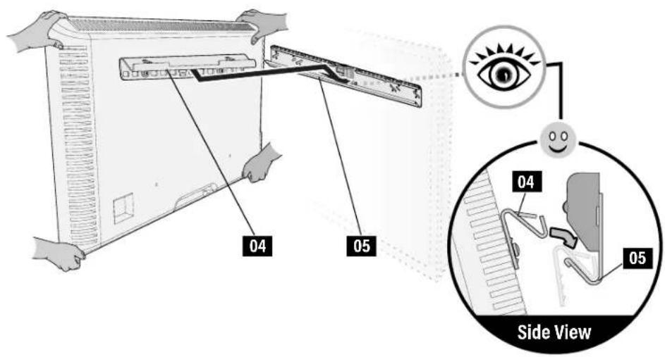
3.2 Hang Your TV

HEAVY! You may need assistance with this step.
IMPORTANT: DO NOT lower TV straight down onto wall plate 05 -- this will engage the lock. Safety latch must be released for proper installation (See STEP 3.1).
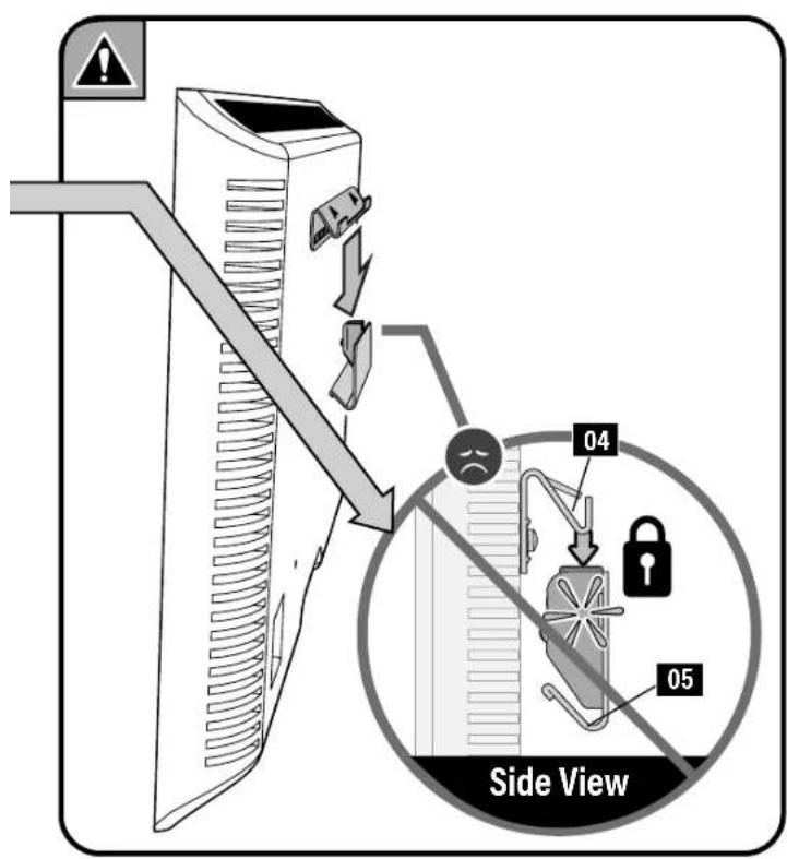
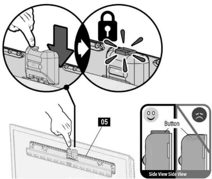
3.3 Lock the Wall Plate
CAUTION: Avoid potential personal injury or property damage! The locking mechanism must be locked, so the TV is securely fastened to the wall plate 05.
3.4 No Tilt Feature (OPTIONAL)
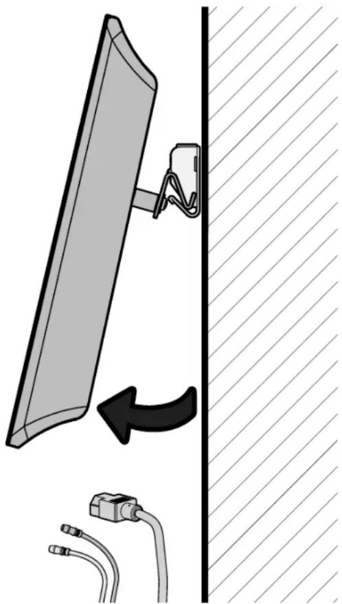
CABLE MANAGEMENT

CAUTION: Avoid potential personal
injury or property damage!
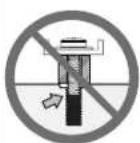
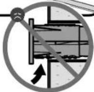
DO NOT force open your TV when adding cables. STOP lifting the bottom outward when you feel resistance.
natural_image
Diagram showing a wall-mounted cable being inserted into a wall, with a close-up of its cable being inserted (no text or symbols present)Adjustments
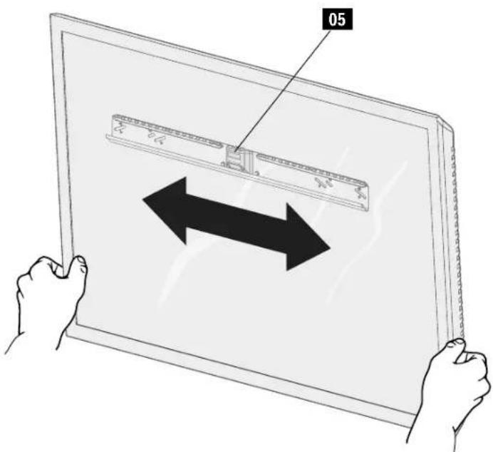
SIDE-TO-SIDE SHIFT
⚠️ CAUTION: Avoid potential personal injury or property damage!
FOR DRYWALL INSTALLATIONS: DO NOT slide the TV side-to-side.
Slide the TV side to side to adjust positioning.
NOTE: Safety stops prevent over-shifting.
Make sure your TV is locked to wall plate 05 (STEP 3.3).
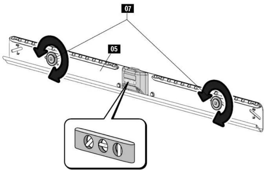
LEVEL [Wood Stud and Concrete Installations]
- Remove the TV.
- Loosen both screws 07
- Adjust the level.
- Retighten both screws 07
To Remove Your TV

HEAVY! You may need assistance with this step.
- Disconnect your cables.
- Unlock wall plate 05 (STEP 3.1).
- Lift the TV up and away from wall plate 05
CAUTION: Avoid potential personal injuries and property damage!
DO NOT reuse this product after removing wall plate 05 from the wall.
SPECIFICATIONS
TV INTERFACE
![24.61in (625mm) MAX 1.54in [39.1mm] 2.95in 75mm MIN](/content/2026/04/676532/images/6a2af8102109cf9f6c87634452825d943cbaa785bbfc3e739428cac35c3a8edf.jpg)
3-D
natural_image
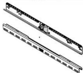
Technical line drawing of a mechanical component or bracket (no text or symbols)WALL PLATE
![2.28in [57.9mm] 17.72in [450mm] 16.00in [406.4mm] 23.62in [600mm] 24.00in [609.6mm]](/content/2026/04/676532/images/e24d4a696e325fefa27c92186dd589b9a158a0e44a6971f56c83dcf2f80f510f.jpg)
3-D
natural_image
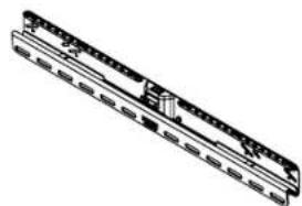
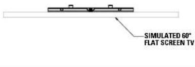
Technical line drawing of a mechanical component with two parallel grooves (no text or symbols)FULLY ASSEMBLED MOUNT
![25.50in [647.7mm] 2.84in [72.3mm]](/content/2026/04/676532/images/5fffb30fdb8b127aed04c24ae37468d2777b7d543bb06af87502cc11f96a8df8.jpg)
TOP VIEW
WALL IS ON TOP
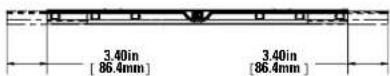
SIDE VIEW
ESPAÑOL
2C.2 Fixez la plaque murale
AVVERTENZA: This product contains a magnet. If an implanted medical device such as a pacemaker or implantable cardioverter defibrillator (CD) is in use, magnetic fields may affect the operation of those devices, resulting in serious injury or death. If you have an implanted medical device keep at least 13 cm (5 in.) between your device and the magnet. Please consult with your physician or medical professional prior to using this product.
A brand of □ le-grand
Legrand AV Inc.
6436 City West Parkway
Eden Prairie, MN 55344 USA
US: +1 (800) 359-5520
SANUS.com
Legrand AV Netherlands B.V.
Franklinstraat 14
6003 DK Weert Netherlands
EMEA: +31 (0) 495 580 852
UK: +44 (0) 800 056 2853
SANUS.com
Authorized Representative for the UK
Starline Holding Technology Ltd.
Unit C Island Road
Reading RG2 ORP UK
Legrand AV Inc. and its affiliated corporations and subsidiaries (collectively, "Legrand"), intend to make this manual accurate and complete. However, Legrand makes no claim that the information contained herein covers all details, conditions, or variations. Nor does it provide for every possible contingency in connection with the installation or use of this product. The information contained in this document is subject to change without notice or obligation of any kind. Legrand makes no representation of warranty, expressed or implied, regarding the information contained herein. Legrand assumes no responsibility for accuracy, completeness or sufficiency of the information contained in this document.
©2022 Legrand AV Inc. All Rights Reserved. SAUNS is a Legrand AV Inc. brand and a registered trademark owned by Legrand. Amazon, Fire and all related marks are trademarks of Amazon.com, Inc. or its affiliates.
Legrand AV Inc. • 6436 City West Parkway • Eden Prairie, MN 55344 USA