Synthesis SDA4600 - Receiver JBL - Free user manual and instructions
Find the device manual for free Synthesis SDA4600 JBL in PDF.

User questions about Synthesis SDA4600 JBL
0 question about this device. Answer the ones you know or ask your own.
Ask a new question about this device
Download the instructions for your Receiver in PDF format for free! Find your manual Synthesis SDA4600 - JBL and take your electronic device back in hand. On this page are published all the documents necessary for the use of your device. Synthesis SDA4600 by JBL.
USER MANUAL Synthesis SDA4600 JBL
IF YOU READ NOTHING ELSE IN THIS GUIDE READ THIS INFORMATION:

WARNING: Before you start to set up your amplifier, read and observe the Important Safety Instructions found at the beginning of this manual.
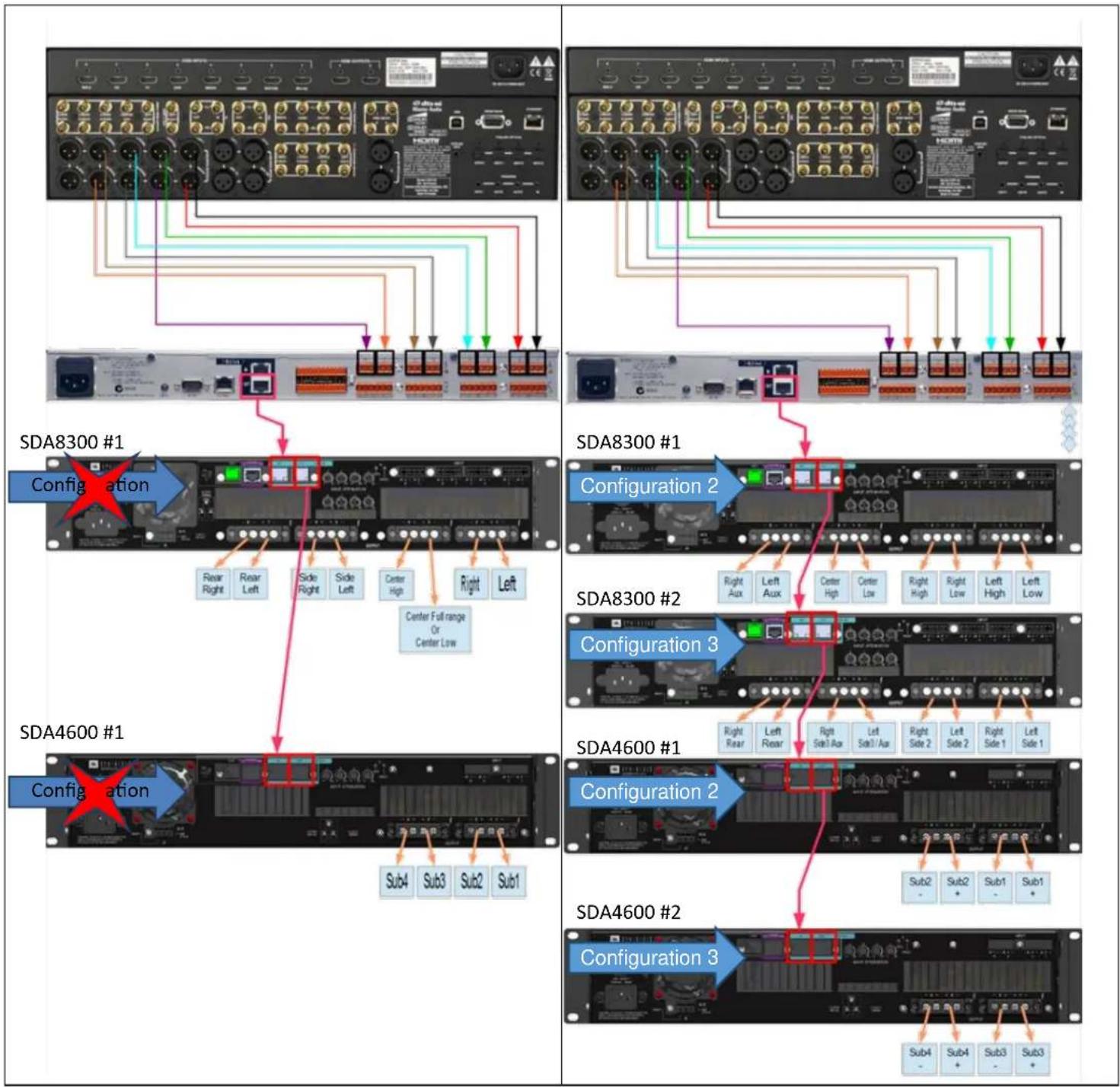
The SDA amplifiers come pre-configured to work with the SDEC4500P using the BLU-LINK digital audio signal over Cat5e Ethernet cables. The amplifiers should not be connected to the home network. Analog audio input comes IN on the SDEC4500P (up to 12 channels) and OUT on the SDA8300 and/or SDA4600 without going through any Digital to Analog conversions (up to 20 Channels as standard, expandable to 128 channels).
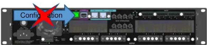
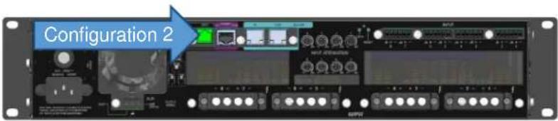
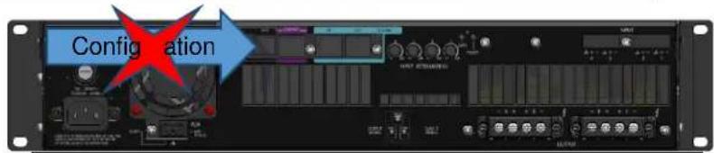
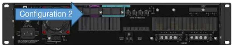
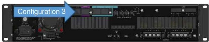
Two alternate configurations are selected by using the included selection trigger that plugs into the GPIO input on the rear panel.
The SDA8300 amplifier ships configured for a simple 7-channel system. The SDA8300 can access two (2) additional configurations. Using combinations of these configurations allows the system to output from a simple 7 x 300 Watt system to up to 16 x 300 Watts with discrete DSP for each channel with active bi-amp outputs on the Left-Center-Right.
The SDA4600 ships configured for a 4-channel subwoofer (4x600 Watts). Up to two (2) additional configurations can be accessed for bridged high power subwoofers outputs (2x1200 Watts) with discrete channel DSP for each output. These are used with the Harman Patented "Sound Field Management" in the SDEC4500P.
The SDEC-4500P controls all DSP and BI-AMP speaker crossover settings and must be configured with either "JBL Synthesis ARCOS" software or "SDEC Control Panel Software v1.5". Go to www.jblsynthesis.com to download the correct software.

CAUTION: Before you begin, make sure your amplifier is disconnected from the power source and that all level controls are set to INF.
Ensure Proper Cooling
When using an equipment rack, mount units directly on top of each other. Close any open spaces in the rack with blank panels.(Open spaces will reduce cooling efficiency.) DO NOT block front or rear air vents. (The rack should be a minimum of two inches (5.1 cm) away from the amplifier, and the back of the rack should be a minimum of four inches (10.2 cm) from the amplifier back panel.
Air flow is front to back.

WARNING: The third prong of this connector (ground) is an important safety feature. Do not attempt to disable this ground connection by using an adapter or other methods.
Fuse
A fuse (F1) located near the IEC power inlet protects the amplifier from excessive AC current draw. The fuse is field replaceable. Replace with same type fuse; LittelFuse 314 Series F20AH 250V. Please contact JBL Service department for more information.
Step by Step Setup Guide
- Connect Preamp/Surround Processor and SDEC4500P
- Connect Blu-Link Digital Audio Link from SDEC4500P to SDA Amplifier(s) using standard Ethernet Cat5e cables
- [Optional] Connect Powered Subwoofers to SDEC4500P
- Setup of SDA8300 for Single (8-channel) or Dual unit (16-channel) configuration and connect speakers
- Setup of SDA4600 for Single (4-channel x 600 W) or Bridged (2-Channel x 1200 W) or Bridged Dual unit configuration and connect subwoofers
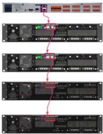
Blu-Link Digital Connection
Digital audio is sent in a daisy-chain from one device to the next using a standard Cat5e patch cable. Connect the OUT from the SDEC4500P to the IN of the first amplifier. Continue with each amplifier in the system connecting from OUT to IN. Up to 60 Amplifiers can be connected with up to 128 discrete channels.
flowchart
graph TD
    A["Server"] --> B["Data Bus"]
    B --> C{Control}
    C -->|Yes| D["Storage System"]
    C -->|No| E["External Control"]
    D --> F["Network Equipment"]
    E --> G["Network Equipment"]
Amplifier Configuration
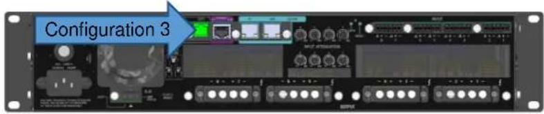
Each amplifier can be configured for different operational modes by using the included jumper plugs and the GPIO port on the rear panel. The plugs are labeled "Configuration 2" and "Configuration 3". Do not connect anything else into the GPIO port.
Configuration 1 would be typical of an standard 7.1 system and combination of Configuration 2 + Configuration 3 would be typical of an expanded 9.4 or active bi-amplified system.
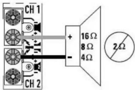
Speaker Connection
Each output of the SDA amplifiers is assigned a specific speaker channel. This is based on the Configuration and the setup of the SDEC4500P for the correct speakers. Use the chart and pictures on the next pages to connect the speakers correctly. Use Category 2 speaker cable.

Never connect the output to a power supply, battery or power main. Electrical shock may result.
SDA8300 Factory Default Configuration 1
| CONFIGURATION 1 | AMP CHANNEL |
| LEFT | 1 |
| RIGHT | 2 |
| CENTER FULL RANGE (CENTER LOW) | 3 |
| CENTER HIGH (BI-AMP ONLY) | 4 |
| SIDE LEFT | 5 |
| SIDE RIGHT | 6 |
| REAR LEFT | 7 |
| REAR RIGHT | 8 |
text_image
Configuration8 channel main speaker system
SDA8300 Configuration 2
| CONFIGURATION 2 | AMP CHANNEL |
| LEFT FULL RANGE / LEFT LOW | 1 |
| LEFT HIGH | 2 |
| RIGHT FULL RANGE / RIGHT LOW | 3 |
| RIGHT HIGH | 4 |
| CENTER FULL RANGE / CENTER LOW | 5 |
| CENTER HIGH | 6 |
| AUX 1 LEFT / HEIGHT LEFT FRONT | 7 |
| AUX 1 RIGHT / HEIGHT RIGHT FRONT | 8 |
text_image
Configuration 216 channel main speaker system (ch1 - ch8)
SDA8300 Configuration 3
text_image
Configuration 316 channel main speaker system (ch9 - ch16)
SDA4600 Factory Default Configuration 1 (600 x 4)
| CONFIGURATION 1 | AMP CHANNEL |
| SUBWOOFER 1 | 1 |
| SUBWOOFER 2 | 2 |
| SUBWOOFER 3 | 3 |
| SUBWOOFER 4 | 4 |
text_image
Configuration4 channel subwoofer speaker system
SDA4600 Configuration 2 (1200 x 2)
| CONFIGURATION 2 | AMP CHANNEL |
| SUBWOOFER 1 | 1 + [POSITIVE] |
| 2 + [NEGATIVE] | |
| SUBWOOFER 2 | 3 + [POSITIVE] |
| 4 + [NEGATIVE] |
text_image
Configuration 2Bridged Subwoofer speaker system (ch1 - ch2)
SDA4600 Configuration 3 (1200 x 2)
| CONFIGURATION 3 | AMP CHANNEL |
| SUBWOOFER 3 | 1 + [POSITIVE] |
| 2 + [NEGATIVE] | |
| SUBWOOFER 4 | 3 + [POSITIVE] |
| 4 + [NEGATIVE] |
text_image
Configuration 3Bridged Subwoofer speaker system (ch3 - ch4)
For low impedance loads, select the appropriate size of wire based on the distance from amplifier to speaker
Distance Wire Size
UP to 25 ft. (7.6 m) 16 AWG
26-40 ft. (7.9-12.2 m) 14 AWG
41-60 ft. (12.5-18.3 m) 12 AWG
60 ft. (18.3 m) 10 AWG
text_image
CH 1 + 16 Ω 8 Ω 4 Ω - CH 2 2Ω
CAUTION: Never use shielded cable for output wiring.

CAUTION: Never connect the speaker return to the chassis of the amplifier, or damage to the amplifier may result.

NOTE: Custom wiring should only be performed by qualified personnel. Class 2 output wiring is required.

CAUTION: To prevent electric shock, do not remove covers. No user serviceable parts inside. Refer servicing to a qualified technician.
flowchart
graph TD
    subgraph_SDA8300_1["Configuration"]
        A1["SDA8300 #1"] --> B1["Center Full range Or Center Low"]
        B1 --> C1["Right Right"]
        B1 --> D1["Right Left"]
        B1 --> E1["Side Right"]
        B1 --> F1["Side Left"]
        B1 --> G1["Center High"]
        B1 --> H1["Right"]
        B1 --> I1["Left"]
    end
    subgraph_SDA8300_2["Configuration 2"]
        J1["SDA8300 #2"] --> K1["Center Full range Or Center Low"]
        K1 --> L1["Right Aux"]
        K1 --> M1["Left Aux"]
        K1 --> N1["Center High"]
        K1 --> O1["Center Low"]
        K1 --> P1["Right High"]
        K1 --> Q1["Right Low"]
        K1 --> R1["Left High"]
        K1 --> S1["Left Low"]
    end
    subgraph_SDA8300_3["Configuration 3"]
        T1["SDA8300 #3"] --> U1["Center Full range Or Center Low"]
        U1 --> V1["Right Rear"]
        U1 --> W1["Left Rear"]
        U1 --> X1["Right Seat Ax"]
        U1 --> Y1["Left Seat Ax"]
        U1 --> Z1["Right Side 2"]
        U1 --> AA1["Left Side 2"]
        U1 --> AB1["Right Side 1"]
        U1 --> AC1["Left Side 1"]
    end
    subgraph_SDA4600_1["Configuration"]
        AD["SDA4600 #1"] --> AE["Sub4"]
        AD --> AF["Sub3"]
        AD --> AG["Sub2"]
        AD --> AH["Sub1"]
    end
    subgraph_SDA4600_2["Configuration 2"]
        AI["SDA4600 #2"] --> AJ["Sub4"]
        AI --> AK["Sub3"]
        AI --> AL["Sub2"]
        AI --> AM["Sub1"]
    end
    subgraph_SDA4600_3["Configuration 3"]
        AN["SDA4600 #2"] --> AO["Sub4"]
        AN --> AP["Sub3"]
        AN --> AQ["Sub2"]
        AN --> AR["Sub1"]
Información General
text_image
Configurationtext_image
Configuration 2Sistema principal de altavoces de 16 canales (ch 1-ch 8)
SDA8300 Configuration 3
| CONFIGURATION 3 | AMP CHANNEL |
| LATERAL IZQUIERDO1 | 1 |
| LADO DERECHO 1 | 2 |
| LADO IZQUIERDO2 | 3 |
| LADO DERECHO 2 | 4 |
| LADO IZQUIERDO 3/ALTURA POSTERIOR IZQUIERDA | 5 |
| LADO DERECHO 3/ALTURA POSTERIOR DERECHA | 6 |
| POSTERIOR IZQUIERDO | 7 |
| POSTERIOR DERECHO | 8 |
text_image
Configuration 3Sistema principal de altavoces de 16 canales (ch 9-ch 16)
SDA4600 Factory Default Configuration 1 (600 x 4)
| CONFIGURATION 1 | AMP CHANNEL |
| SUBWOOFER 1 | 1 |
| SUBWOOFER 2 | 2 |
| SUBWOOFER 3 | 3 |
| SUBWOOFER 4 | 4 |
text_image
Configurationtext_image
Configuration 2text_image
Configuration 3flowchart
graph TD
    subgraph_SDA8300_1["Configuration"]
        A1["SDA8300 #1"] --> B1["Center Full range Or Center Low"]
        B1 --> C1["Rear Right"]
        B1 --> D1["Rear Left"]
        B1 --> E1["Side Right"]
        B1 --> F1["Side Left"]
        B1 --> G1["Center High"]
        B1 --> H1["Right"]
        B1 --> I1["Left"]
    end
    subgraph_SDA8300_2["Configuration"]
        J1["SDA8300 #2"] --> K1["Center Full range Or Center Low"]
        K1 --> L1["Right Aux"]
        K1 --> M1["Left Aux"]
        K1 --> N1["Center High"]
        K1 --> O1["Center Low"]
        K1 --> P1["Right High"]
        K1 --> Q1["Right Low"]
        K1 --> R1["Left High"]
        K1 --> S1["Left Low"]
    end
    subgraph_SDA8300_3["Configuration"]
        T1["SDA8300 #2"] --> U1["Center Full range Or Center Low"]
        U1 --> V1["Right Rear"]
        U1 --> W1["Left Rear"]
        U1 --> X1["Right Sub 3 Ax"]
        U1 --> Y1["Left Sub 1 Ax"]
        U1 --> Z1["Right Sub 2"]
        U1 --> AA1["Left Sub 2"]
        U1 --> AB1["Right Sub 1"]
        U1 --> AC1["Left Sub 1"]
    end
    subgraph_SDA4600_1["Configuration"]
        AD["SDA4600 #1"] --> AE["Sub4"]
        AD --> AF["Sub3"]
        AD --> AG["Sub2"]
        AD --> AH["Sub1"]
    end
    subgraph_SDA4600_2["Configuration"]
        AI["SDA4600 #2"] --> AJ["Sub4"]
        AI --> AK["Sub3"]
        AI --> AL["Sub2"]
        AI --> AM["Sub3"]
    end
text_image
Configurationtext_image
Configuration 2text_image
Configuration 3| CONFIGURATION 1 | AMP CHANNEL |
| SUBWOOFER 1 | 1 |
| SUBWOOFER 2 | 2 |
| SUBWOOFER 3 | 3 |
| SUBWOOFER 4 | 4 |
text_image
Configurationtext_image
Configuration 2text_image
Configuration 3flowchart
graph TD
    A["Network Port 1"] --> B["Configuration 2"]
    B --> C["SDA8300 #1"]
    C --> D["Right Aux"]
    C --> E["Left Aux"]
    C --> F["Center High"]
    C --> G["Center Low"]
    C --> H["Right High"]
    C --> I["Right Low"]
    C --> J["Left High"]
    C --> K["Left Low"]
    B --> L["Configuration 3"]
    L --> M["SDA8300 #2"]
    M --> N["Right Rear"]
    M --> O["Left Rear"]
    M --> P["Right Side1 Aux"]
    M --> Q["Left Side1 Aux"]
    M --> R["Right Side 2"]
    M --> S["Left Side 2"]
    M --> T["Right Side 1"]
    M --> U["Left Side 1"]
    M --> V["Sub2 -"]
    M --> W["Sub2 +"]
    M --> X["Sub1 -"]
    M --> Y["Sub1 +"]
    M --> Z["Sub4 -"]
    M --> AA["Sub4 +"]
    M --> AB["Sub3 -"]
    M --> AC["Sub3 +"]
Speaker Connection /
SDA
SDEC4500P
2
SDA8300 Factory Default Configuration 1 / SDA8300 1
| CONFIGURATION 1 / 1 | AMP CHANNEL/ | Configuration |
| LEFT / | 1 | |
| RIGHT / | 2 | |
| CENTER FULL RANGE (CENTER LOW) ( ) | 3 | |
| CENTER HIGH (BI-AMP ONLY) ( ) | 4 | 8 channel main speaker system.8 . |
| SIDE LEFT / | 5 | |
| SIDE RIGHT / | 6 | |
| REAR LEFT / | 7 | |
| REAR RIGHT / | 8 |
JBL SYNTHESIS SDA8300 / SDA4600 QUICKSTART

SDA8300 Configuration 2 / SDA8300 구성 2
A fuse (F1) located near the IEC power inlet protects the amplifier from excessive AC current draw. The fuse is field replaceable. Replace with same type fuse; LittelFuse 314 Series F20AH 250V. The 8|600 and 4|250 utilize a resettable breaker instead of a fuse. Please contact JBL Service department for more information.
开五
4 channel subwoofer speaker system.
4채널 서브우퍼 스피커 시스템.
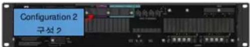
SDA4600 Configuration 2 / SDA4600 구성 2
| CONFIGURATION 2 :구성 2 | AMP CHANNEL/일프 채널 |
| SUBWOOFER 1서보우퍼 1 | 1 + [POSITIVE]1 + [방국] |
| 2 + [NEGATIVE]2 + [음국] | |
| SUBWOOFER 2서보우퍼 2 | 3 + [POSITIVE]3 + [방국] |
| 4 + [NEGATIVE]4 + [음국] |
text_image
Configuration 2 구분 2Bridged Subwoofer speaker system (ch1 - ch2).