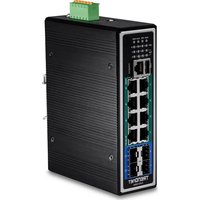
TI-PG1284i - Switch TRENDNET - Free user manual and instructions
Find the device manual for free TI-PG1284i TRENDNET in PDF.


| Product Type | Managed Industrial DIN Rail Switch |
| Brand | TRENDnet |
| Model | TI-PG1284i |
| Number of Ports | 12 Gigabit Ethernet Ports |
| PoE+ Power | Yes, up to 30 W per port, total PoE budget depends on external power supply |
| Power Supply | Screw terminal block, requires external power supply (sold separately, e.g. TI-S48048, TI-S24048) |
| DIN Rail Support | Yes, with included mounting bracket |
| Management | Local (web interface) or cloud via TRENDnet Hive |
| Default IP Address | 192.168.10.200 / 255.255.255.0 |
| System Requirements | Computer with RJ-45 cable, DHCP server (for cloud) |
| Safety Instructions | Disconnect power before connection; respect polarities and voltage on label |
| Grounding | Possible via grounding terminal (wire not included) |
| Additional Equipment | SFP modules (e.g. TI-MGBSX, TI-MGBS10), 35 mm DIN rail |
| Package Contents | Switch, quick installation guide, console cable |
| Standards | EN 55032:2015 + A11:2020 Class A, EN 55035:2017 + A11:2020 |
| Directives | EMC 2014/30/EU, REACH (EC) No 1907/2006, WEEE 2012/19/EU |
| Manufacturer | TRENDnet, Inc., Torrance, California, USA |
Frequently Asked Questions - TI-PG1284i TRENDNET
User questions about TI-PG1284i TRENDNET
0 question about this device. Answer the ones you know or ask your own.
Ask a new question about this device
Download the instructions for your Switch in PDF format for free! Find your manual TI-PG1284i - TRENDNET and take your electronic device back in hand. On this page are published all the documents necessary for the use of your device. TI-PG1284i by TRENDNET.
USER MANUAL TI-PG1284i TRENDNET
natural_image
Four black TRENNET industrial networking devices with Ethernet ports and I/O ports, no visible text or labels on the devices themselves.Quick Installation Guide
Industrial PoE L2 Managed Switches
Table of Contents
1 English
- Before You Start
- Quick Reference
- Hardware Installation
- Hardware Configuration
12 Français
1. Before You Start
Package Contents
• TI-PG1284i / TI-PG541i / TI-PG102i / TI-PG102i-M / TI-BG62i / TI-PG103i / TI-PG743Bi
• Quick Installation Guide
- Console cable
Minimum Requirements
• Power supply (ex. model TI-S48048, TI-S24048, TI-S24052, TI-S15052, TI-S12048)
• Networked computer
• RJ-45 Network Cable
Optional Equipment
• 35 mm DIN-Rail
- SFP modules (e.g. TI-MGBSX, TI-MGBS10, TI-MGBS20, TI-MGBS40, TI-MGBRJ)
2. Quick Reference
Note: The switch may be different than the one shown in the examples.
3. Hardware Installation
Note:
The maximum amount of power available is 30 Watts per port. If a power overload has occurred, the switch will prioritize the distribution of power by port (from lowest to highest). For example, port 1 will receive the highest priority and port 8 will receive the lowest priority. The ports with lower priority will have its PoE function disabled until more than 7.5 watts of power becomes available.
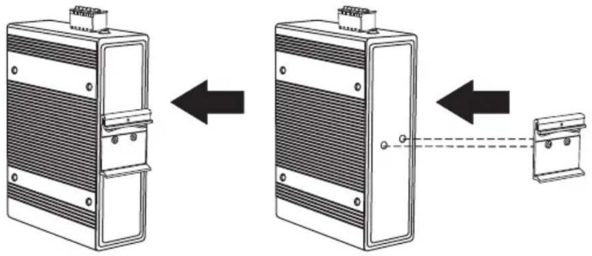
The switch can be placed on a desktop or mounted to a DIN-Rail.
DIN-Rail Mounting Instructions
- switch.Attach the DIN-Rail mount to
natural_image
Diagram showing three stages of a device with internal components and connection points (no text or symbols)-
Position the unit in front of the DIN-Rail and hook the mount bracket over the top of the rail.
-
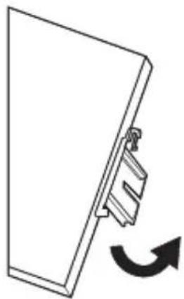
Rotate the switch downward towards the rail to lock it into place. You will know it is secure when you hear a click.
natural_image
Simple line drawing of a mechanical component with an arrow indicating rotational motion (no text or symbols)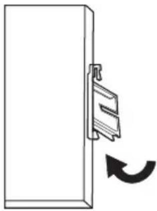
natural_image
Simple line drawing of a door with a clip attached to the left side and a curved arrow indicating rotation (no text or symbols)Mounting the unit Releasing the unit
- To remove the unit, pull down to clear the bottom of the DIN-Rail and rotate away from the rail.
Applying Power
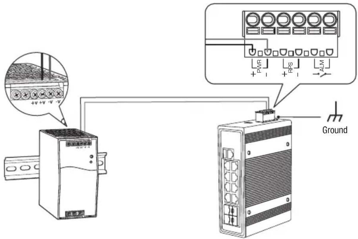
Note: Do not connect the power supply to a power source until the terminal connections are secured with the steps below.
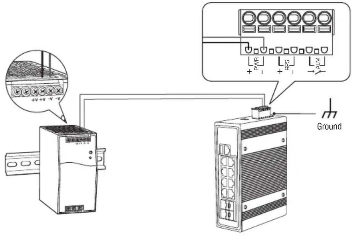
- Connect the power supply (sold separately) to the included terminal block (as shown below) and secure with the screws.
Note: Polarities must match.
- Attach the terminal block to the unit.
Optional: The switch chassis can also be connected to a known grounding point for additional safety and protection (grounding wire is not included).
Safety Note

- Turn off the power before connecting any module or wire. The correct power supply voltage is listed on the product label. Check the voltage of your power source to make sure that you are using the correct part. Do NOT use voltage greater than voltage range, as specified on the product label.
- Calculate the maximum possible current in each power wire and common wire. Observe all electrical codes dictating the maximum current allowable for each wire size. If the current surpasses the maximum ratings, the wiring could overheat, causing serious damage to your equipment.
4. Hardware Installation and Configuration
Note: If you are configuring the switch to be managed from your existing TRENDnet Hive cloud account, please follow the steps in Section A: Configuring the switch with TRENDnet Hive Cloud Management. If you are configuring the switch for local network management only, please follow the steps in Section B: Configuring the switch for local network management.
Section A: Configuring the switch with TRENDnet Hive Cloud Management
Note: Configuration with TRENDnet Hive Cloud Management requires an existing network with Internet access and DHCP server for automatic IP addressing. The switch must be configured to reach the Internet in order to connect to your TRENDnet Hive Cloud Management account.
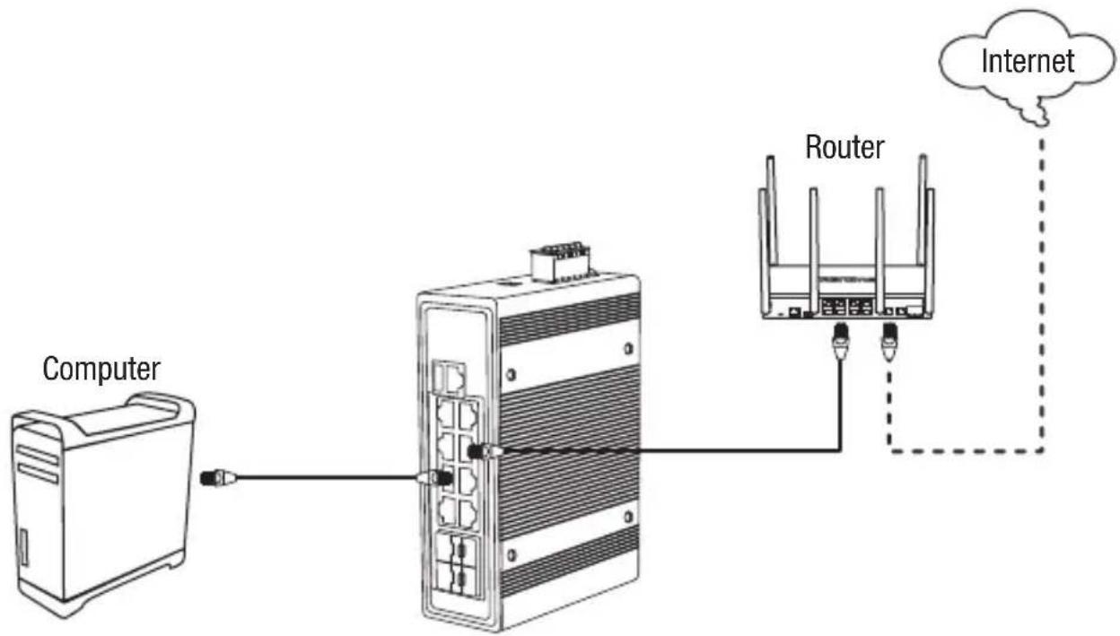
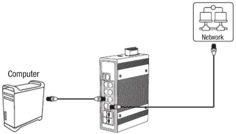
- Connect an Ethernet/network cable to your computer and one of the switch ports.
- Connect another Ethernet/network cable to one of your switch ports and to your existing network or router with Internet access and DHCP server for automatic IP addressing.
flowchart
graph LR
    A["Computer"] --> B["Server"]
    B --> C["Router"]
    C --> D["Internet"]
    style A fill:#f9f,stroke:#333
    style B fill:#ccf,stroke:#333
    style C fill:#cfc,stroke:#333
    style D fill:#fcc,stroke:#333
- Assign a Static IP address to your computer's network adapter in the subnet of 192.168.10.x (e.g. 192.168.10.25) and a subnet mask of 255.255.255.0.
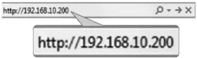
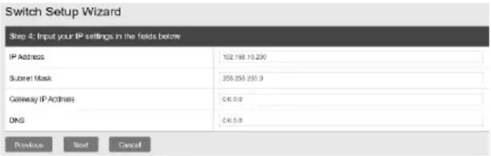
- Open your web browser, type the IP address of the switch in the address bar, and then press Enter. The default IP address is 192.168.10.200 / 255.255.255.0.
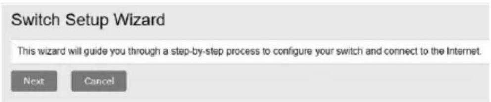
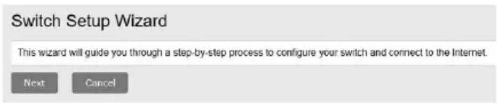
5. Click Next on the Switch Setup Wizard.
Note: If the switch setup wizard does not appear, you can click the setup wizard button in the top right section of the switch management page to access the switch setup wizard.
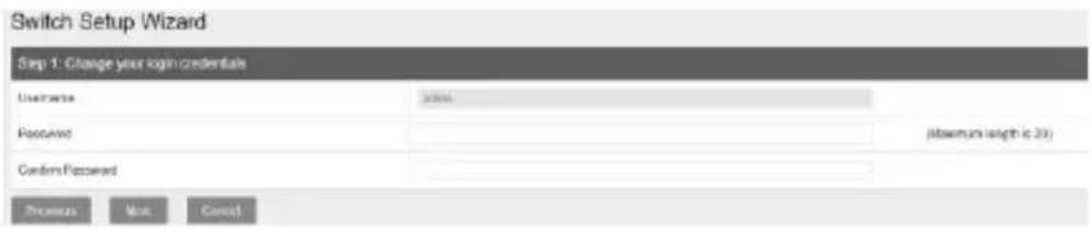
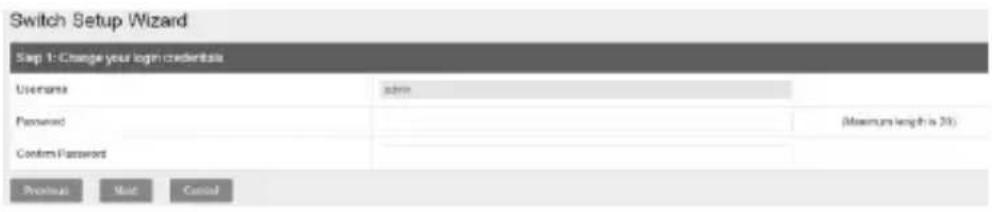
- You can change the switch administrator password by typing in the new password in the fields provided, then click Next.
Note: If entering a new password, please note that you will need to use the new password when logging into the switch management page for local management access moving forward.
- For the method of management, select TRENDnet Hive.
Note: Configuration with TRENDnet Hive Cloud Management requires an existing network with Internet access and DHCP server for automatic IP addressing. The switch must be configured to reach the Internet in order to connect to your TRENDnet Hive Cloud Management account. If the switch is unable to reach to obtain IP address settings and DNS from the DHCP server and unable to reach the Internet, registration of the switch to your TRENDnet Hive cloud management account will fail.

- After selecting TRENDnet Hive, click Next and change your computer's network adapter settings to obtain an IP address automatically to continue the rest of the setup wizard.
Note: After selecting the TRENDnet Hive option and clicking Next, the switch will immediately change the switch default IP address settings to DHCP and obtain IP address settings from your existing network.

- Select your Time Zone, then click Next.
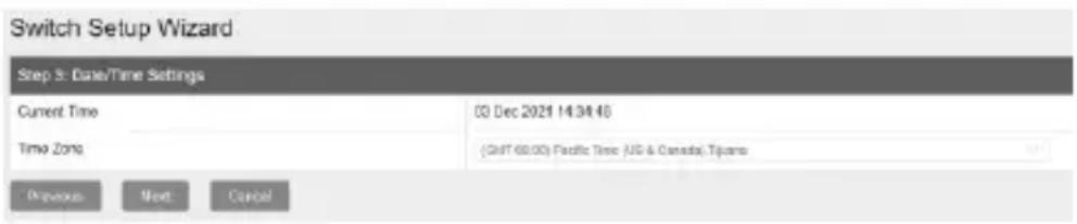
- Enter the user account credentials for your TRENDnet Hive Cloud Management account to register the switch with your account, then click Next.
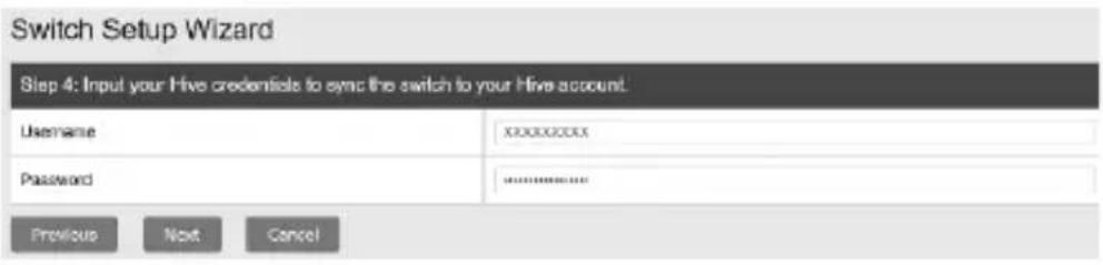
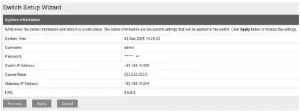
- The summary page will display all of the configuration settings that were applied through the setup wizard. Click Apply to complete the setup wizard.
Note: You may want to note the new password and IP address settings for local management access to switch.
- To verify the switch is now successfully registered with your TRENDnet Hive Cloud Management account, the Hive button in the top right will be green to indicate successful registration.
Section B: Configuring the switch for local network management
- Connect an Ethernet/network cable to your computer and one of the switch ports.
- Assign a Static IP address to your computer's network adapter in the subnet of 192.168.10.x (e.g. 192.168.10.25) and a subnet mask of 255.255.255.0.
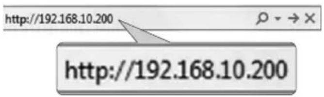
- Open your web browser, type the IP address of the switch in the address bar, and then press Enter. The default IP address is 192.168.10.200 / 255.255.255.0.
- Click Next on the Switch Setup Wizard.
Note: If the switch setup wizard does not appear, you can click the setup wizard button in the top right section of the switch management page to access the switch setup wizard.
- You can change the switch administrator password by typing in the new password in the fields provided, then click Next.
Note: If entering a new password, please note that you will need to use the new password when logging into the switch management page for local management access moving forward.
- For the method of management, select Default Management.

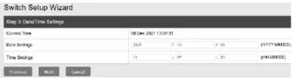
- Configure the switch date and time settings, then click Next.
- Configure the switch IP address, subnet mask, gateway IP address, and DNS settings to match the requirements of your existing network using the fields provided, then click Next. Note: If the switch IP address settings are changed to a different IP network subnet such as 192.168.1.x, 192.168.2.x, etc. your computer's network adapter settings will need to be changed to match the new IP address settings configured on the switch in order to access the switch management page.
- The summary page will display all of the configuration settings that were applied through the setup wizard. Click Apply to complete the setup wizard.
Note: You may want to note the new password and IP address settings for local management access to switch.

Note: To download the latest version of the User's Guide and the utility, please go to https://www.trendnet.com/support and select the from the products Switch Model drop-down list.
natural_image
Simple line drawing of a mechanical component with an arrow indicating rotational motion (no text or symbols)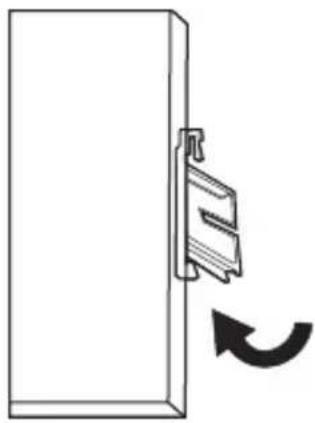
natural_image
Simple line drawing of a door with a clip attached to the left side, showing a curved arrow indicating rotation (no text or symbols)natural_image
Simple line drawing of a mechanical component with an arrow indicating rotational motion (no text or symbols)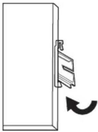
natural_image
Simple line drawing of a door with a clip attached to the left side, showing a curved arrow indicating rotation (no text or symbols)Section B: Configuring the switch for local network management
flowchart
graph LR
    A["Rectangular Device"] --> B["Door"]
    B --> C["Small Bracket"]
natural_image
Simple line drawing of a mechanical component with an arrow indicating rotational motion (no text or symbols)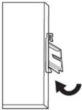
natural_image
Simple line drawing of a door with a clip attached to the left side, showing a curved arrow indicating rotation (no text or symbols)natural_image
Diagram showing three stages of a device with internal components and directional arrows indicating movement (no text or symbols)natural_image
Simple line drawing of a mechanical clip attached to a flat panel, with an arrow indicating rotational motion (no text or symbols)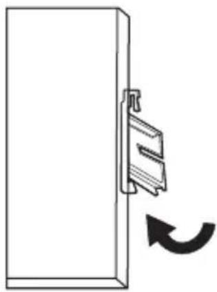
natural_image
Simple line drawing of a door handle with a clip and arrow indicating rotation (no text or symbols)This wizard will guide you through a step-by-step process to configure your switch and connect to the Internet.
Next
Cancel
natural_image
Diagram showing three stages of a device with internal components and directional arrows indicating movement (no text or symbols present)natural_image
Simple line drawing of a mechanical component with an arrow indicating rotational motion (no text or symbols)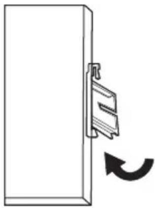
natural_image
Simple line drawing of a door with a clip attached to the left side and a curved arrow indicating rotation (no text or symbols)Declaration of Conformity
TRENDNET®
Manufacturer's Name and Address
TRENDnet, Inc.
The Hague The Netherlands
Torrance, CA 90501 USA

Product Information:
Model Number: TI-PG1284i/TI-PG541i/TI-PG102i/TI-PG102i-M/TI-BG62i/TI-PG103i/TI-PG743Bi
Product Name:
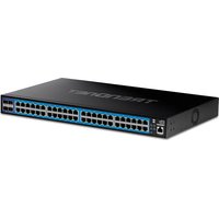
12-Port Industrial Gigabit L2 Managed PoE+DIN-Rail Switch
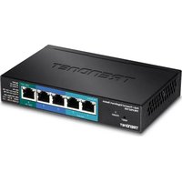
6-Port Hardened Industrial Gigabit PoE+ Layer 2 Managed DIN-Rail Switch
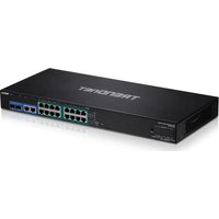
10-Port Industrial Gigabit L2 Managed PoE+DIN-Rail Switch 24 - 57V
10-Port Industrial Gigabit L2 Managed PoE+DIN-Rail Switch 24 - 57V
6-Port Industrial Glgabit L2 Managed PoE+DIN-Rail Switch
10-Port Industrial Gigabit L2 Managed PoE+DIN-Rail Switch 24 - 57V
7-Port Industrial Gigabit L2 Managed PoE+DIN-Rail Switch 24 - 57V
Trade Name: TRENDnet
TRENDnet hereby declare that the product is in compliance with the essential requirements and other relevant provisions under our sole responsibility.
EMC
EN 55032:2015 + A11:2020 Class A
EN 55035:2017 + A11:2020
CISPR 2015 + CORI:2016
EN 55011:2016 + A11: 2020 Group 1 Class A (TI-BG62i, TI-PG541i, TI-PG743Bi)
EN 61000-6-2:2019 (TI-BG62i, TI-PG541i, TI-PG743Bi)
EN 61000-6-4:2007 + A1: 2011 (TI-BG62i)
EN 61000-6-4:2019 (TI-PG541i, TI-PG7438i)
This product is herewith confirmed to comply with the Directives.
Directives:
EMC Directive 2014/30/EU
RoHS Directive 2011/65/EU
RoHS 3 Directive 2015/863/EU
REACH Regulation (EU) No. 1907/2006
WEEE Directive 2012/19/EU
Person responsible for this declaration.
Place of Issue: Torrance, California, USA
Date: March 27, 2025
Name: Sonny Su
Title: VP of Technology
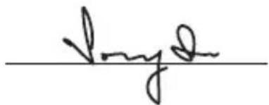
Signature:

The Hague The Netherlands
Torrance, CA 90501 USA

Détails du produit:
CISPR 2015 + CORI:2016
EN 55011:2016 + A11: 2020 Group 1 Class A (TI-BG62i, TI-PG541i, TI-PG743Bi)
EN 61000-6-2:2019 (TI-BG62i, TI-PG541i, TI-PG743Bi)
EN 61000-6-4:2007 + A1: 2011 (TI-BG62i)
EN 61000-6-4:2019 (TI-PG541i, TI-PG7438i)
Directive RoHS 2011/65/UE
Directive 2015/863/UE (RoHS 3)
Title: VP of Technology
Signature:

The Hague The Netherlands
Torrance, CA 90501 USA

CISPR 2015 + CORI:2016
EN 55011:2016 + A11: 2020 Group 1 Class A (TI-BG62i, TI-PG541i, TI-PG743Bi)
EN 61000-6-2:2019 (TI-BG62i, TI-PG541i, TI-PG743Bi)
EN 61000-6-4:2007 + A1: 2011 (TI-BG62i)
EN 61000-6-4:2019 (TI-PG541i, TI-PG7438i)
Titel: Vice President of Technology
Unterschrift:

Manufacturer's Name and Address
TRENDnet, Inc.
Authorized Representative:
20675 Manhattan Place
Office: +44 (0) 1635 887 399
Torrance, CA 90501 USA
Unit 4 Rivermead Business Park,
Pipers Way, Thatcham, R 19 4EP EnglandG

Product Information:
Model Number: TI-PG1284i/TI-PG541i/TI-PG102i/TI-PG102i-M/TI-BG62i/TI-PG103i/TI-PG743Bi
Product Name:
12-Port Industrial Gigabit L2 Managed PoE+DIN-Rail Switch
6-Port Hardened Industrial Gigabit PoE+ Layer 2 Managed DIN-Rail Switch
10-Port Industrial Gigabit L2 Managed PoE+DIN-Rail Switch 24 - 57V
10-Port Industrial Gigabit L2 Managed PoE+DIN-Rail Switch 24 - 57V
6-Port Industrial Glgabit L2 Managed PoE+DIN-Rail Switch
10-Port Industrial Gigabit L2 Managed PoE+DIN-Rail Switch 24 - 57V
7-Port Industrial Gigabit L2 Managed PoE+DIN-Rail Switch 24 - 57V
Trade Name: TRENDnet
TRENDnet hereby declare that the product is in compliance with the essential requirements and other relevant provisions under our sole responsibility.
EMC
BS EN 55032:2015 + A11:2020 Class A
BS EN 55035:2017 + A11:2020
CISPR 2015 + CORI:2016
BS EN 55011:2016 + A11: 2020 Group 1 Class A (TI-BG62i, TI-PG541i, TI-PG743Bi)
BS EN 61000-6-2:2019 (TI-BG62i, TI-PG541i, TI-PG743Bi)
BS EN 61000-6-4:2007 + A1: 2011 (TI-BG62i)
BS EN 61000-6-4:2019 (TI-PG541i, TI-PG7438i)
This product is herewith confirmed to comply with the Directives.
Directives:
Electromagnetic Compatibility Regulations 2016
The Restriction of the Use of Certain Hazardous Substances in Electrical and
Electronic Equipment Regulations 2012
The REACH Enforcement Regulations 2008 (as amended)
The Waste Electrical and Electronic Equipment Regulations 2013 (as amended)
Person responsible for this declaration.
Place of Issue: Torrance, California, USA
Date: March 27, 2025
Name: Sonny Su
Title: VP of Technology
Signature:

Certifications
This device complies with Part 15 of the FCC Rules. Operation is subject to the following two conditions: (1) This device may not cause harmful interference. (2) This device must accept any interference received. Including interference that may cause undesired operation.


Waste electrical an electronic products must not be disposed of with household waste. Please recycle where facilities exist. Check with your Local Authority or Retailer for recycling advice.
- This equipment has been tested and found to comply with the limits for a Class A digital device, pursuant to part 15 of the FCC Rules. These limits are designed to provide reasonable protection against harmful interference when the equipment is operated in a commercial environment. This equipment generates, uses, and can radiate radio frequency energy and, if not installed and used in accordance with the instruction manual, may cause harmful interference to radio communications. Operation of this equipment in a residential area is likely to cause harmful interference in which case the user will be required to correct the interference at his own expense. - FCC Caution: Any changes or modification not expressly approved by the party responsible for compliance could void the user's authority to operate this equipment.
Technical Support
If you have any questions regarding the product installation, please contact our Technical Support. Toll free US/Canada: 1-855-373-4741 Regional phone numbers available at www.trendnet.com/support
TRENDnet
20675 Manhattan Place Torrance, CA 90501 USA
Applies to PoE Products Only: This product is to be connected only to PoE networks without routing to the outside plant.
Note
The Manufacturer is not responsible for any radio or TV interference caused by unauthorized modifications to this equipment. Such modifications could void the user's authority to operate the equipment.
Advertencia
Power supply connected caution
The equipment power supply cord shall be connected to a socket-outlet with earthing connection.
Advertencia
If the Optical Transceiver doesn't ship with the unit, the user manual shall have description as below or equivalent: "This product is intended to be use with a UL Listed Optical Transceiver product, Rated DC3.3V, Laser Class I."
Wall-mounted instructions
The Unit has two wall-mount slots on its bottom panel. Before you begin, make sure you have two screws that indicate a diameter measurement of 0.265748 inches (6.75mm). (1) Determine where you want to mount the modem. (2) Maneuver the modem so the wall-mount slots line up with the two screws. (3) Place the wall-mount slots over the screws and slide the modem down until the screws fit snugly into the wall-mount slots. (4) Screw type P3.5 x 16mm x 2
Product Warranty Registration
Please take a moment to register your product online. Go to TRENDnet's website at: www.trendnet.com/register
- Table of Contents
- English
- Français
- Before You Start
- Package Contents
- Minimum Requirements
- Optional Equipment
- Quick Reference
- Hardware Installation
- Note:
- DIN-Rail Mounting Instructions
- Applying Power
- Safety Note
- Hardware Installation and Configuration
- Section A: Configuring the switch with TRENDnet Hive Cloud Management
- Click Next on the Switch Setup Wizard.
- Section B: Configuring the switch for local network management
- Declaration of Conformity
- TRENDNET®
- Manufacturer's Name and Address
- Product Information:
- Product Name:
- Trade Name: TRENDnet
- EMC
- Directives:
- Détails du produit:
- Certifications
- Technical Support
- TRENDnet
- Note
- Advertencia
- Power supply connected caution
- Wall-mounted instructions
- Product Warranty Registration
Brand : TRENDNET
Model : TI-PG1284i
Category : Switch