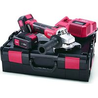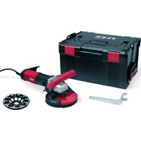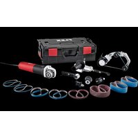
BRE 8-4 INOX Set - Sander Flex - Free user manual and instructions
Find the device manual for free BRE 8-4 INOX Set Flex in PDF.


User questions about BRE 8-4 INOX Set Flex
0 question about this device. Answer the ones you know or ask your own.
Ask a new question about this device
Download the instructions for your Sander in PDF format for free! Find your manual BRE 8-4 INOX Set - Flex and take your electronic device back in hand. On this page are published all the documents necessary for the use of your device. BRE 8-4 INOX Set by Flex.
USER MANUAL BRE 8-4 INOX Set Flex
natural_image
Illustration of three types of electric motors with different mechanical components (no text or symbols)de Originalbetriebsanleitung 3
en Original operating instructions 18
fr Notice d'instructions d'origine 32
it Istruzioni per l'uso originali 49
es Instrucciones de funcionamiento originales ..... 65
pt Instruções de serviço originais 81
nl Originele gebruiksaanwijzing 97
da Originale driftsvejledning 114
no Originale driftsanvisningen 129
sv Originalbruksanvisning 144
fi Alkuperäinen käyttöohjekirja 158
el Auθεντικές οδηγίες χειρισμού 173
tr Orijinal işletme kılavuzu 189
pl Instrukcja oryginalna 204
hu Eredeti üzemeltetési útmutató 221
cs Originální návod k obsluze 236
sk Originálny návod na obsluhu 251
hr Originalna uputa za rad 266
sl Izvirno navodilo za obratovanje 281
ro Instructiuni de functionare originale 295
bg Оригинално упътване за експлоатация ..... 310
ru Оригинальная инструкция по эксплуатации ..... 327
et Originaalkasutusjuhend 345
It Originali naudojimo instrukcija 360
Iv Lietošanas pamācības oriģināls 375
ar 403
ترجمة لارشادات الأتشغير الأصلية
Inhalt
Verwendete Symbole 3
Symbole am Gerät 3
text_image
Technical diagram showing mechanical assembly steps with numbered instructions for tool manipulationtext_image
Technical diagram illustrating three-step mechanical assembly steps with numbered annotationstext_image
Technical diagram showing three-step assembly of a mechanical device with labeled parts and directional arrows indicating motion.natural_image
Illustration of a hand using a power tool to move on a textured surface with directional arrows indicating motion (no text or symbols)natural_image
Mechanical assembly diagram showing a mechanical component with three parts and a directional arrow indicating motion (no text or symbols)Rollen wechseln
text_image
1. 2. 3. 30 mmAntriebsrolle:
text_image
Diagram showing hands operating a mechanical device with a belt drive system labeled 21 and 22text_image
Technical diagram showing mechanical assembly steps with numbered annotations indicating component identificationtext_image
Technical diagram of a mechanical linkage mechanism with numbered steps and component viewsnatural_image
Mechanical assembly diagram showing a grinding tool with a cylindrical component and rotating shaft (no text or symbols)natural_image
Illustration of a hand using a crimping tool to adjust a mechanical component (no text or symbols visible)natural_image
Illustration of a hand using a tool to adjust or install a mechanical component, with arrows indicating motion (no text or symbols present)natural_image
Diagram of a car interior showing a grille and directional arrow (no text or symbols)Klaus Peter Weinper Head of Quality Department (QD)
06.06.2018
Symbols used in this manual ..... 18
Symbols on the power tool.....18
For your safety 18
Noise and vibration. 22
Technical specifications ..... 23
Overview 24
Instructions for use 25
Maintenance and care .... 30
Disposal information....31
C ∈-Declaration of Conformity. . . . . . . . 31
Exemption from liability 31
Symbols used in this manual

WARNING!
Denotes impending danger. Non-observance of this warning may result in death or extremely severe injuries.

CAUTION!
Denotes a possibly dangerous situation. Non-observance of this warning may result in slight injury or damage to property.

NOTE
Denotes application tips and important information.
Symbols on the power tool

Before switching on the power tool, read the operating manual!

Wear goggles!

Protection class II (completely insulated)

Disposal information for the old machine (see page 31)
For your safety

WARNING!
Before using the angle grinder, please read and follow:
– these operating instructions,
- the "General safety instructions" on the handling of power tools in the enclosed booklet (leaflet-no.: 315.915),
– the currently valid site rules and the regulations for the prevention of accidents.
This angle grinder is state of the art and has been constructed in accordance with the acknowledged safety regulations.
Nevertheless, when in use, the power tool may be a danger to life and limb of the user or a third party, or the power tool or other property may be damaged. The angle grinder may be operated only if it is
-as intended,
– in perfect working order.
Faults which impair safety must be repaired immediately.
Intended use
The drive unit BME 8-4 must be used solely as a drive for the attachments described below.
With the burnishing attachment BSE 8-4 50 the power tool is intended
– for commercial use in industry and trade,
– for the machining of surfaces, such as the satinising, structuring, polishing, brushing, smoothing, derusting or deburring of steel, stainless steel or non-ferrous metals,
– for use with tools which are offered for this machine by the manufacturer.
It is not permitted to machine the surface of wood.
With the belt sander attachment BRE 8-4 the power tool is intended
– for commercial use in industry and trade,
– for finishing stainless steel pipes, round railing parts,
– for sanding round bar profiles as well as pipes in general,
– for use with sanding belts and accessories which are specified in these instructions or recommended by the manufacturer.
With the belt grinder attachment FBE 8-4 the power tool is intended
– for commercial use in industry and trade,
– for grinding and polishing metallic surfaces in areas with limited access,
– for use with sanding belts and accessories which are specified in these instructions or recommended by the manufacturer.
Safety Instructions for power tools with a burnishing attachment

WARNING!
Read all safety warnings and all instructions. Failure to follow the warnings and instructions may result in electric shock, fire and/or serious injury. Save all warnings and instructions for future reference.
Common safety instructions for polishing and working with a wire brush
■ This power tool is intended for use as a polisher and for working with a wire brush. Read all safety warnings, instructions, illustrations and specifications provided with this power tool. Failure to follow all instructions listed below may result in electric shock, fire and/or serious injury.
■ Operations such as grinding or abrasive cutting-off operations are not recommended to be performed with this power tool. Operations for which the power tool was not designed may create a hazard and cause personal injury.
■ Do not use accessories which are not specifically designed and recommended by the tool manufacturer. Just because the accessory can be attached to your power tool, it does not assure safe operation.
■ The rated speed of the accessory must be at least equal to the maximum speed marked on the power tool. Accessories running faster than their rated speed can break and fly apart.
■ The outside diameter and the thickness of your accessory must be within the capacity rating of your power tool. Incorrectly sized accessories cannot be adequately guarded or controlled.
- Threaded mounting of accessories must match the grinder spindle thread. For accessories mounted by flanges, the arbour hole of the accessory must fit the locating diameter of the flange.
Accessories that do not match the mounting hardware of the power tool will run out of balance, vibrate excessively and may cause loss of control.
■ Do not use a damaged accessory. Before each use inspect the accessory such as abrasive wheels for chips and cracks, backing pad for cracks, tear or excess
wear, wire brush for loose or cracked wires. If power tool or accessory is dropped, inspect for damage or install an undamaged accessory. After inspecting and installing an accessory, position yourself and bystanders away from the plane of the rotating accessory and run the power tool at maximum no-load speed for one minute. Damaged accessories will normally break apart during this test time.
■ Wear personal protective equipment. Depending on application, use face shield, safety goggles or safety glasses. As appropriate, wear dust mask, hearing protectors, gloves and workshop apron capable of stopping small abrasive or workpiece fragments. The eye protection must be capable of stopping flying debris generated by various operations. The dust mask or respirator must be capable of filtrating particles generated by your operation. Prolonged exposure to high intensity noise may cause hearing loss.
- Keep bystanders a safe distance away from work area. Anyone entering the work area must wear personal protective equipment. Fragments of workpiece or of a broken accessory may fly away and cause injury beyond immediate area of operation.
- Hold the power tool by the insulated grips as the grinding surface could touch the connection lead. Damage to a “live” wire may make exposed metal parts of the power tool “live” and cause an electric shock.
■ Position the cord clear of the spinning accessory. If you lose control, the cord may be cut or snagged and your hand or arm may be pulled into the spinning accessory.
■ Never lay the power tool down until the accessory has come to a complete stop. The spinning accessory may grab the surface and pull the power tool out of your control.
■ Do not run the power tool while carrying it at your side. Accidental contact with the spinning accessory could snag your clothing, pulling the accessory into your body.
- Regularly clean the power tool's air vents. The motor's fan will draw the dust inside the housing and excessive accumulation of powdered metal may cause electrical hazards.
■ Do not operate the power tool near flammable materials. Sparks could ignite these materials.
■ Do not use accessories that require liquid coolants. Using water or other liquid coolants may result in electrocution or shock.
Kickback and Related Warnings
Kickback is a sudden reaction to a pinched or snagged rotating wheel, backing pad, brush or any other accessory. Pinching or snagging causes rapid stalling of the rotating accessory which in turn causes the uncontrolled power tool to be forced in the direction opposite of the accessory's rotation at the point of the binding. For example, if an abrasive wheel is snagged or pinched by the workpiece, the edge of the wheel that is entering into the pinch point can dig into the surface of the material causing the wheel to climb out or kick out. The wheel may either jump toward or away from the operator, depending on direction of the wheel's movement at the point of pinching. Abrasive wheels may also break under these conditions. Kickback is the result of power tool misuse and/or incorrect operating procedures or conditions and can be avoided by taking proper precautions as given below.
■ Maintain a firm grip on the power tool and position your body and arm to allow you to resist kickback forces. Always use auxiliary handle, if provided, for maximum control over kickback or torque reaction during start-up. The operator can control torque reactions or kickback forces, if proper precautions are taken.
■ Never place your hand near the rotating accessory. Accessory may kickback over your hand.
- Do not position your body in the area where power tool will move if kickback occurs. Kickback will propel the tool in direction opposite to the wheel's movement at the point of snagging.
■ Use special care when working corners, sharp edges etc. Avoid bouncing and snagging the accessory. Corners, sharp edges or bouncing have a tendency to snag the rotating accessory and cause loss of control or kickback.
■ Do not attach a saw chain woodcarving blade or toothed saw blade. Such blades create frequent kickback and loss of control.
Safety Warnings Specific for Sanding Operations
■ Do not use excessively oversized sanding disc paper. Follow manufacturers recommendations, when selecting sanding paper. Larger sanding paper extending beyond the sanding pad presents a laceration hazard and may cause snagging, tearing of the disc, or kickback.
Safety Warnings Specific for Polishing Operations
- Do not allow any loose portion of the polishing bonnet or its attachment strings to spin freely. Tuck away or trim any loose attachment strings. Loose and spinning attachment strings can entangle your fingers or snag on the workpiece.
Safety Warnings Specific for Wire Brushing Operations
■ Be aware that wire bristles are thrown by the brush even during ordinary operation. Do not overstress the wires by applying excessive load to the brush. The wire bristles can easily penetrate light clothing and/or skin.
■ If the use of a guard is recommended for wire brushing, do not allow any interference of the wire wheel or brush with the guard. Wire wheel or brush may expand in diameter due to work load and centrifugal forces.
Safety Instructions for power tools with a pipe belt sander attachment

WARNING!
Read all safety warnings and all instructions. Failure to follow the warnings and instructions may result in electric shock, fire and/or serious injury. Save all warnings and instructions for future reference.
■ Hold the device by the insulated grip surfaces, as the sanding belt may come into contact with the power cord itself. A damaged live cable may cause metal parts of the device to become live and result in an electric shock.
■ Do not use the electric power tool if it has a damaged power cord. Do not touch the damaged power cord and pull out the mains plug if the power cord is damaged during work. Damaged power cords increase the risk of an electric shock.
■ Use the electric power tool for dry sanding only. If water penetrates the electric power tool, there is an increased risk of electric shock.
■ When working, guide the electric power tool with both hands. The handle must be attached! Do not switch on the machine until both hands are in the grip position.
- Keep hands away from the running sanding belt. There is a risk of injury caused by crushing in the area of the guide rollers. On account of the operating mode and the guaranteed flexibility of the power tool these danger areas cannot be completely shielded.
■ Dust released from materials, such as lead paints, some types of wood, minerals and metal, may be hazardous to the operator or people in the vicinity. Inhaling or touching these dusts may result in respiratory diseases and/or allergic reactions.
- Ensure the work place is well ventilated!
- If possible, use external dust extraction.
- It is recommended to wear a respirator mask belonging to filter class P2.
■ Do not work on materials which release hazardous substances (e.g. asbestos).
■ Never grind or cut light metals which have a magnesium content greater than 80%. Risk of fire!
■ If power tools are used outdoors or are exposed to excessive amounts of metal dust, connect them via a residual-current-operated circuit-breaker (tripping current maximum 30 mA). Do not use any worn, torn or severely clogged sanding belts. Damaged sanding belts may rip, fly off and cause an injury.
■ Before using the machine, check that the grinding tools have been installed and secured correctly. Switch on the machine at no load for 30 seconds!
- Interrupt the test run immediately if violent vibrations occur or other damage is established. Check the machine to determine the cause.
■ Do not load electric power tool to such an extent that it comes to a standstill or the sanding belt slips.
■ Before putting down the electric power tool, switch it off and wait until it comes to a standstill.
■ Do not clamp the electric power tool in a vice.
■ Always lay the power cord to the rear away from the electric power tool.
■ Clamp the workpiece if it is loose or not positioned securely by its own weight.
■ Store and handle grinding tools according to the manufacturer's instructions.
Safety instructions for power tool with belt grinder attachment

WARNING!
Read all safety instructions and other instructions. Failure to observe the safety instructions and other instructions may result in an electric shock, fire and/or serious injuries. Keep all safety instructions and other instructions in a safe place for the future.
■ Hold the device by the insulated grip surfaces, as the sanding belt may come into contact with the power cord itself. A damaged live cable may cause metal parts of the device to become live and result in an electric shock.
■ Do not use the electric power tool if it has a damaged power cord. Do not touch the damaged power cord and pull out the mains plug if the power cord is damaged during work. Damaged power cords increase the risk of an electric shock.
■ Use the electric power tool for dry sanding only. If water penetrates the electric power tool, there is an increased risk of electric shock.
■ When working, guide the electric power tool with both hands. The handle must be attached! Do not switch on the machine until both hands are in the grip position.
- Keep hands away from the running sanding belt. There is a risk of injury caused by crushing in the area of the guide rollers. On account of the operating mode and the guaranteed flexibility of the power tool these danger areas cannot be completely shielded.
■ Dust released from materials, such as lead paints, some types of wood, minerals and metal, may be hazardous to the operator or people in the vicinity. Inhaling or touching these dusts may result in respiratory diseases and/or allergic reactions.
- Ensure the work place is well ventilated!
- If possible, use external dust extraction.
- It is recommended to wear a respirator mask belonging to filter class P2.
■ Do not work on materials which release hazardous substances (e.g. asbestos).
■ Never grind or cut light metals which have a magnesium content greater than 80%. Risk of fire!
■ If power tools are used outdoors or are exposed to excessive amounts of metal dust, connect them via a residual-current-operated circuit-breaker (tripping current maximum 30 mA). Do not use any worn, torn or severely clogged sanding belts. Damaged sanding belts may rip, fly off and cause an injury.
■ Before using the machine, check that the grinding tools have been installed and secured correctly. Switch on the machine at no load for 30 seconds!
■ Interrupt the test run immediately if violent vibrations occur or other damage is established. Check the machine to determine the cause.
■ Do not place the power tool under such load that it comes to a halt or the sanding belt slips.
■ Before putting down the power tool, switch it off and wait until it comes to a standstill.
■ Do not clamp the power tool in a vice.
■ Always lay the power cord to the rear away from the electric power tool.
■ Clamp the workpiece if it is loose or not positioned securely by its own weight.
■ Store and handle grinding tools according to the manufacturer's instructions.
Additional safety instructions
■ Use only extension cables permitted for outdoor use.
■ Identify the power tool with stickers only. Do not drill any holes into the housing.
■ The mains voltage and the voltage specifications on the rating plate must correspond.
Noise and vibration

NOTE
Values for the A-weighted sound pressure level and for the total vibration values can be found in the “Technical specifications” table.
The noise and vibration values have been determined in accordance with EN 60745.

CAUTION!
The indicated measurements refer to new power tools. Daily use causes the noise and vibration values to change.

NOTE
The vibration emission level given in this information sheet has been measured in accordance with a standardised test given in EN 60745 and may be used to compare one tool with another. It may be used for a preliminary assessment of exposure. The declared vibration emission level represents the main applications of the tool. However if the tool is used for different applications, with different accessories or poorly maintained, the vibration emission may differ. This may significantly increase the exposure level over the total working period.
However if the tool is used for different applications, with different accessories or poorly maintained, the vibration emission may differ. This may significantly decrease the exposure level over the total working period.
Identify additional safety measures to protect the operator from the effects of vibration such as: maintain the tool and the accessories, keep the hands warm, organisation of work patterns.

CAUTION!
Wear ear protection at a sound pressure above 85 dB(A).
Technical specifications
| Machine type | Burnishing machineBSE 8-4 50 | Pipe belt sanderBRE 8-4 | Belt grinderFBE 8-4 | |
| Power input W 800 | ||||
| Power output W 325 | ||||
| Rated speed | r.p.m. | 4500 | ||
| No load speed | r.p.m. | 1400-4000 | ||
| Tool ∅ max. mm 125 - - | ||||
| Tool width mm 50 - - | ||||
| Tool holder mm 19 - - | ||||
| Belt dimensions(length x width) | mm - 533x4-30 | 533x4-9 | ||
| Belt speed | m/s | - | 3-8 | |
| Weight according to “EPTA Procedure 01/2003” | ||||
| Drive without attachments cable | kg 1.8 | |||
| Drive with attachment (without cable) | kg | 2.3 | 2.7 | 2.6 |
| Schutzklasse | II/☐ | |||
| A-weighted sound pressure level according to EN 60745 (see “Noise and vibration”): | ||||
| Sound pressure level L_pA | dB(A) | 81.2 | 81.6 | 81.4 |
| Sound power level L_WA | dB(A) | 92.2 | 92.6 | 92.4 |
| Uncertainty K | db 3.0 | |||
| Total vibration value according to EN 60745 (see “Noise and vibration”): | ||||
| Emission value a_h when ...– satinising metal surfaces– sanding metal pipes | m/s^2 | 3.5- | -< 2.5 | -< 2.5 |
| Uncertainty K | m/s^2 | 1.5 | ||
Overview
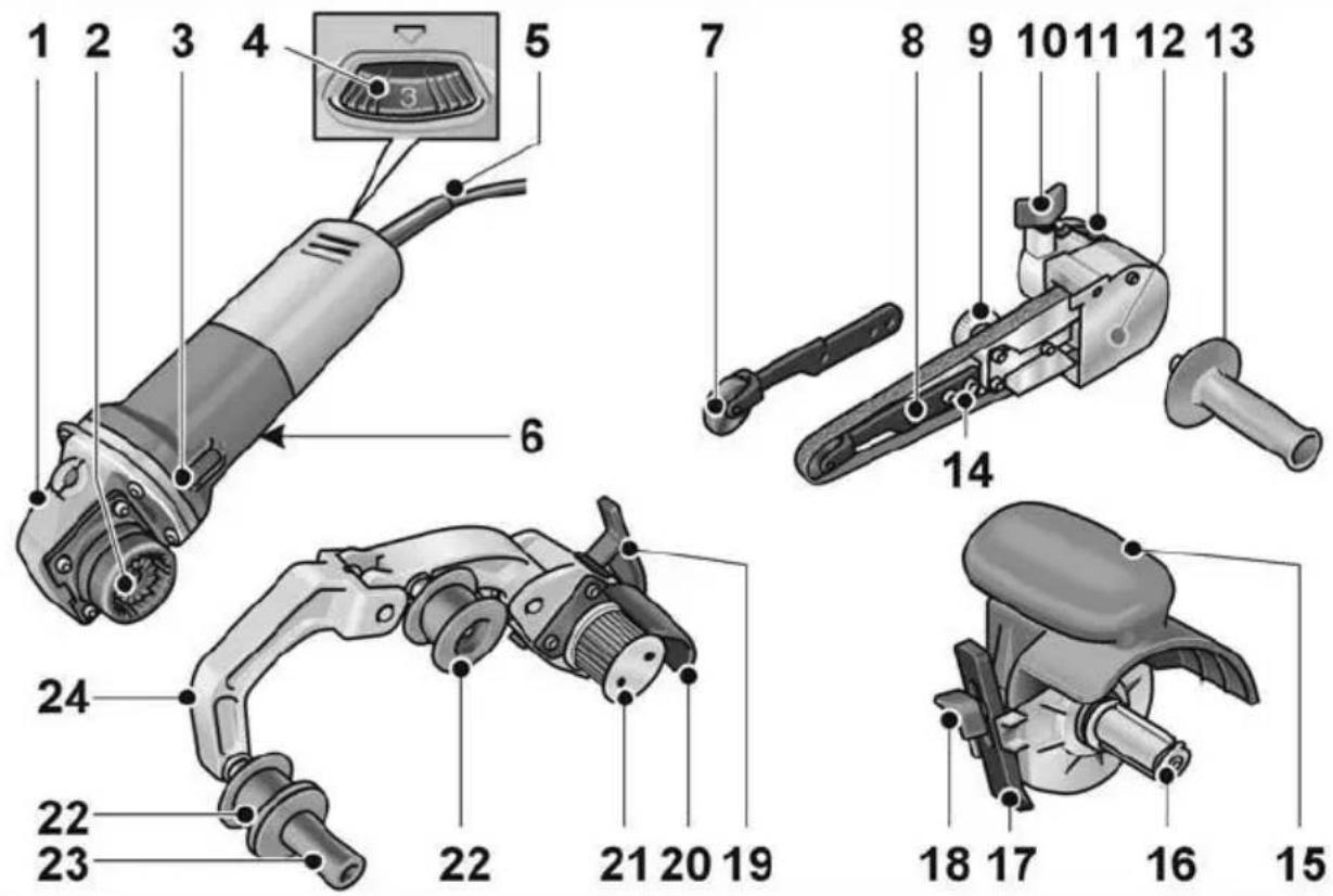
Drive unit BME 8-4
1 Gear head
2 Snap coupling for attachments
3 Switch rocker
Switches the power tool on and off.
With notched position for continuous operation.
4 Dial for preselecting the speed
5 4,0 m power cord with plug
6 Rating plate *)
Belt grinder attachment FBE 8-4
7 Contact roller with sanding arm
8 Securing bolt/adjusting bolt for setting belt course
9 Eccentric bolt
10 Locking bolt for sanding attachment
11 Release lever for snap coupling
12 Housing cover
13 Handle
14 Securing bolts for sanding arm
Belt sander attachment BSE 8-4 5 0
15 Guard with handle
16 Tool holder
17 Parallel guide
18 Locking screw for parallel guide and attachment
Pipe belt sander attachment BRE 8-4
19 Clamping lever for snap coupling
20 Protective cover
21 Drive roller with thrust rings
22 Idler with thrust rings
23 Handle
24 Swing arm
Spring-mounted, for tensioning the sanding belt.
Instructions for use

WARNING!
Before performing any work on the electric power tool, pull out the mains plug.
Before switching on the power tool
Unpack the drive unit and attachments, and check that no parts are missing or were damaged during transport.
Mounting attachments
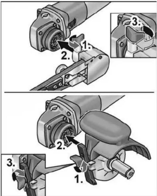
■ Place the required attachment on a level work surface with the snap coupling facing upwards.
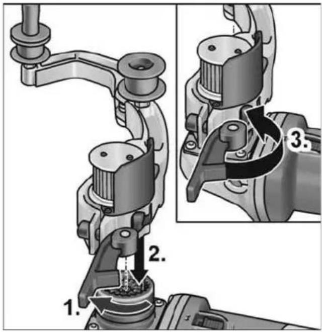
text_image
Technical diagram showing mechanical assembly steps with numbered instructions for tool manipulation■ Open the clamping lever on the attachment (1.).
■ Place the drive unit in the required position to the attachment and press down until it audibly engages (2.).
■ Close the clamping lever (3.).
i NOTE
The gear teeth in the snap coupling of the drive unit and the attachment are automatically interlocked when the machine is switched on.
Removal of attachments
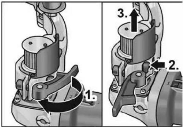
text_image
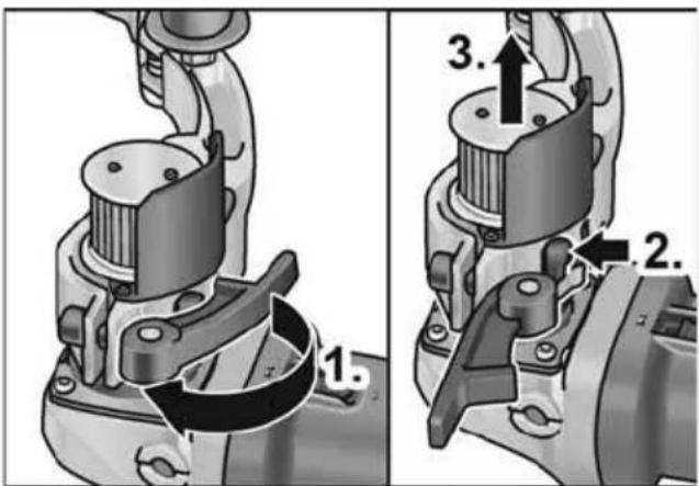
1. 2. 3.■ Open the clamping lever on the attachment (1.).
■ Press and hold down the release lever (2.).
■ Lift the drive unit off the attachment (3.).
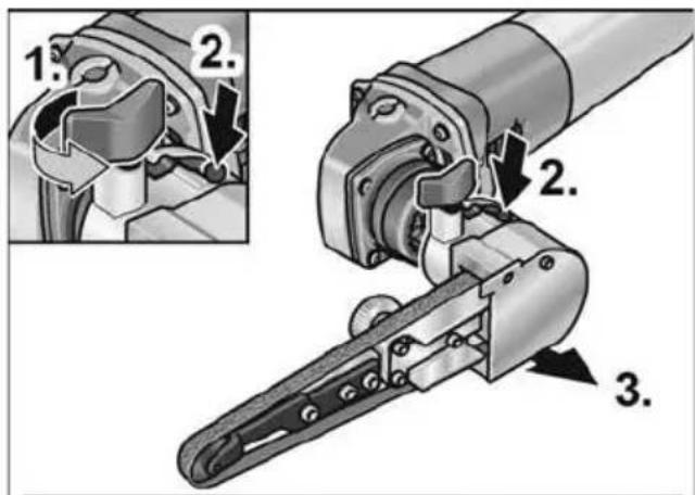
text_image
1. 2. 2. 3.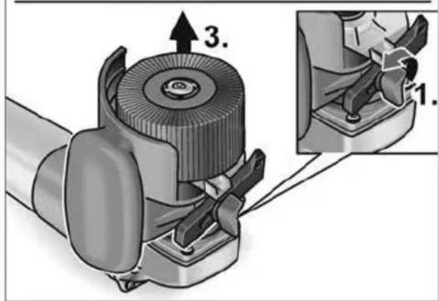
text_image
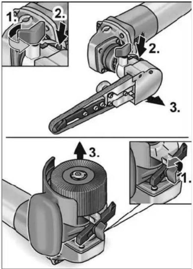
3. 1.■ Loosen locking bolt on attachment (1.).
■ Push and hold down release lever (2.).
■ Lift up attachment (3.).
Attaching tool
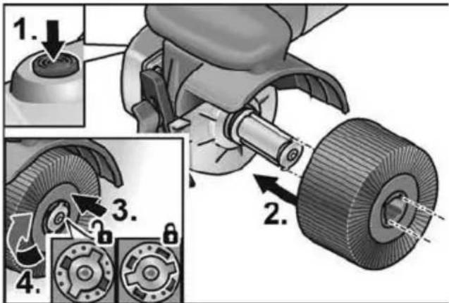
The tool holder enables the tool to be changed without any tools.
■ Pull out the mains plug.
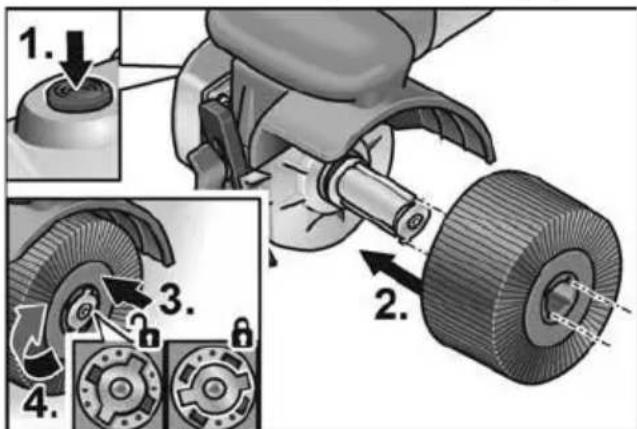
■ Press and hold down the spindle lock (1.).
text_image
1. 2. 3. 4.■ Push tool or tool support onto the tool holder (tongue and groove form fit) (2.).
■ Press the tool downwards against the spring pressure (3.) and turn clockwise (4.). The tool holder is locked.
i NOTE
The tool holder has a width of 50 mm. Depending on the tool width, several tools must be attached or differences in width must be equalised with the spacer rings. Example:
| Polishing wheel 50 mm wide: | 1 tool |
| Buffing wheel 10 mm wide: | 4 tools and spacer rings |
■ Insert the mains plug into the socket.
■ Switch on the electric power tool (without locking the button) and leave it running for approx. 30 seconds. Check for imbalances and vibrations.
■ Switch off the electric power tool.
Using the parallel guide
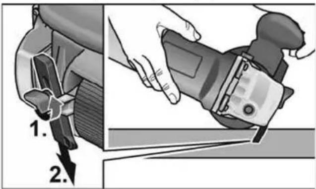
The parallel guide ensures exact straight running when machining profiles.
■ Loosen the locking screw on the parallel guide (1.).
■ Adjust the parallel guide (2.).
text_image
1. 2.■ Re-tighten the locking screw. Work instructions for the burnishing attachment
CAUTION!
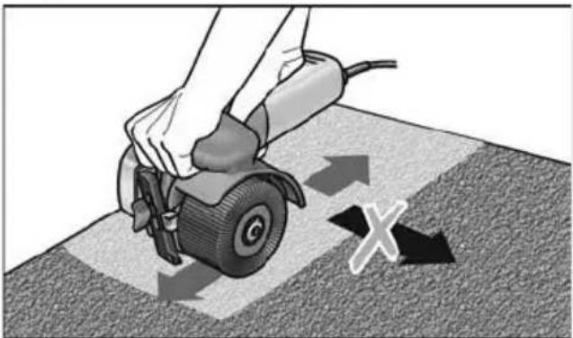
When the appliance is switched off, the grinding tool continues running briefly. Machining flat areas:
■ Hold electric power tool with both hands. To give the surface a decorative finish:
natural_image
Illustration of a hand using a power tool to cut a tire on a textured surface, with directional arrows indicating motion (no text or symbols)■ Carefully place the electric power tool on the area to be machined and move the power tool forwards and backwards in a linear motion.
Belt sander attachment BRE 8-4

WARNING!
Before performing any work on the electric power tool, pull out the mains plug.
Attaching or changing the sanding belt

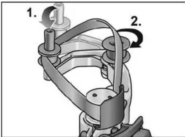
CAUTION!
Observe the specified running direction of the belt! Running direction must correspond with the arrow on the gear head.
■ Pull out the mains plug.
■ Press the swing arm towards the rubber drive roller and hold down (1.).
text_image
1. 2.■ Place the sanding belt over the rollers (2.).
■ Release the swing arm.
■ Check that the belt is situated fully on the rollers.
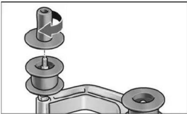
Adjusting the handle
Bring the handle into position on the thread.
natural_image
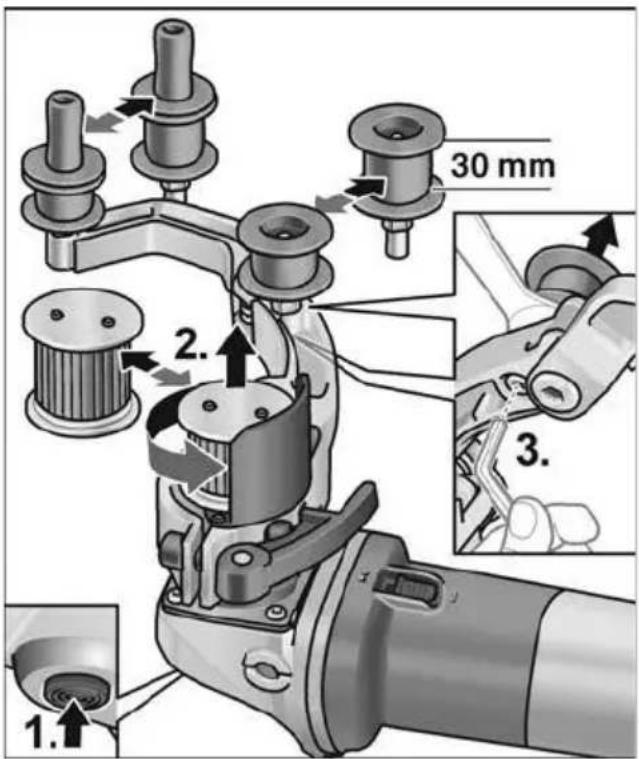
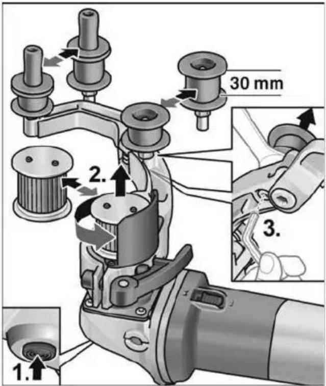
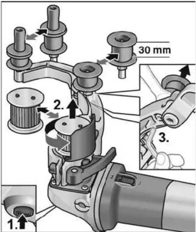
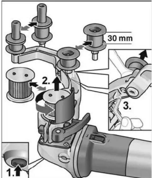
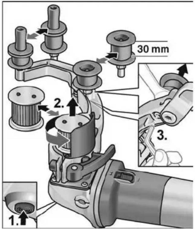
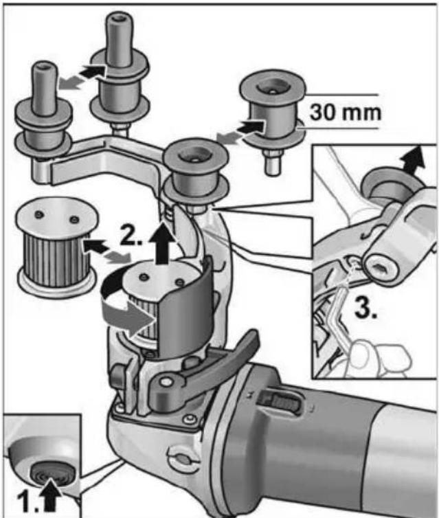
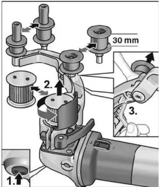
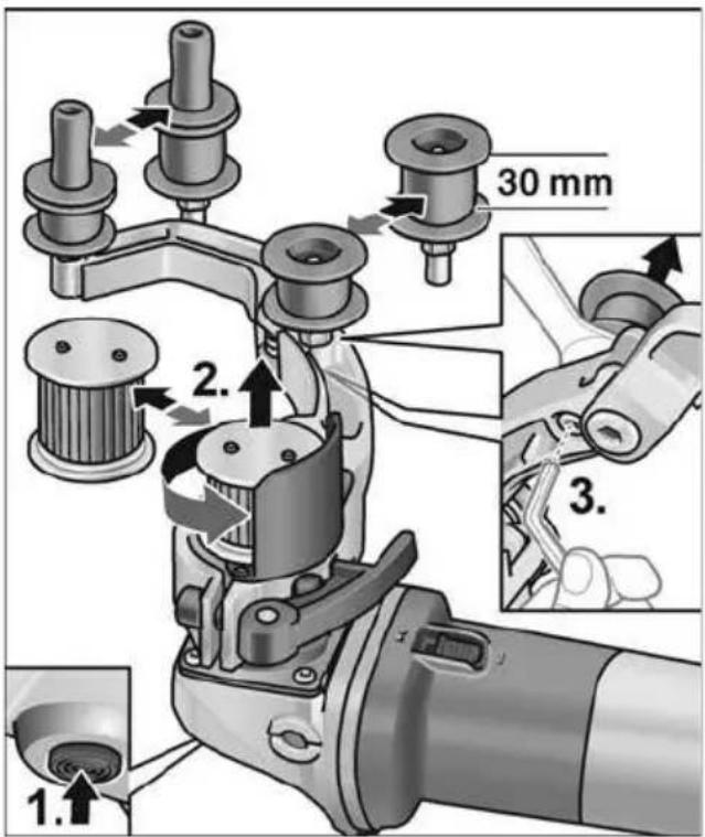
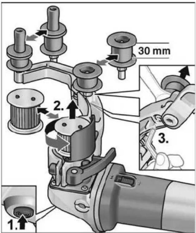
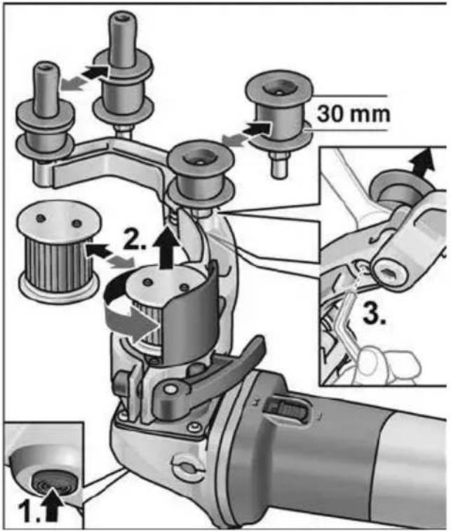
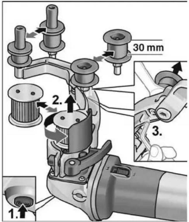
Mechanical assembly diagram showing a pin inserted into a housing component (no text or symbols visible)Change the rollers
text_image
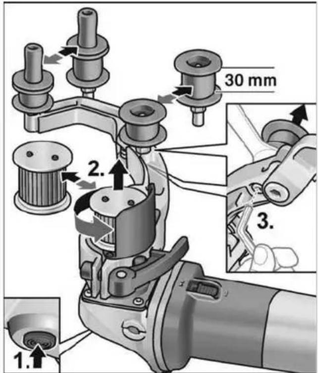
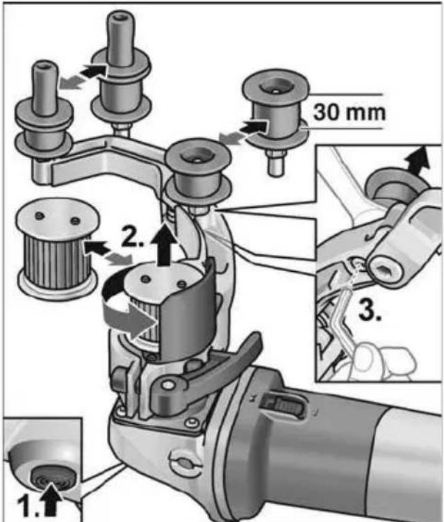
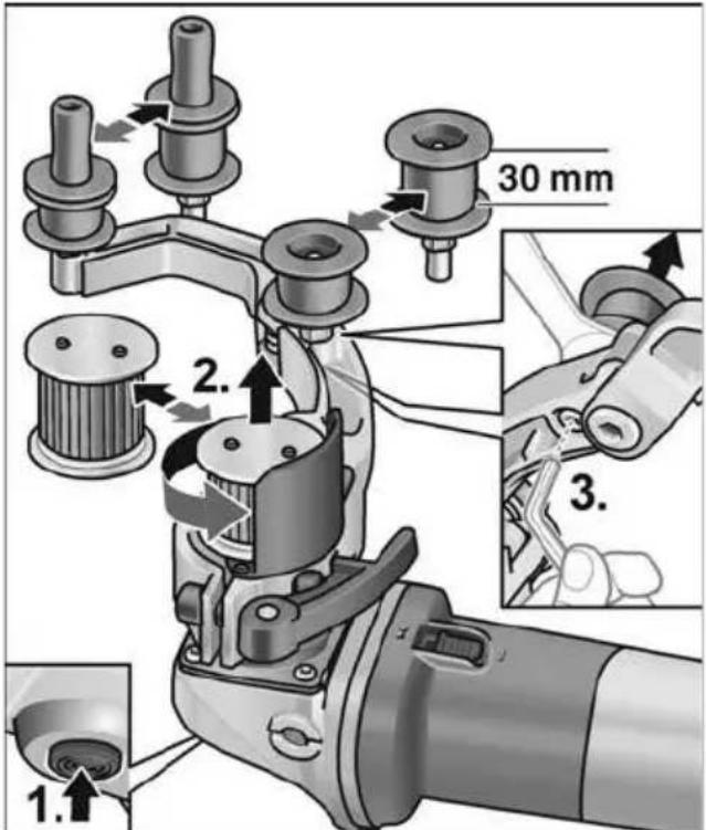
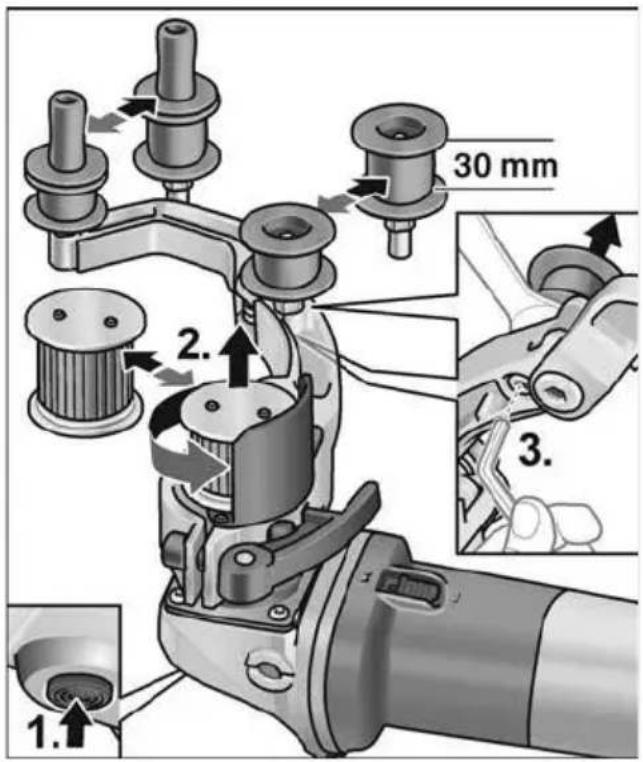
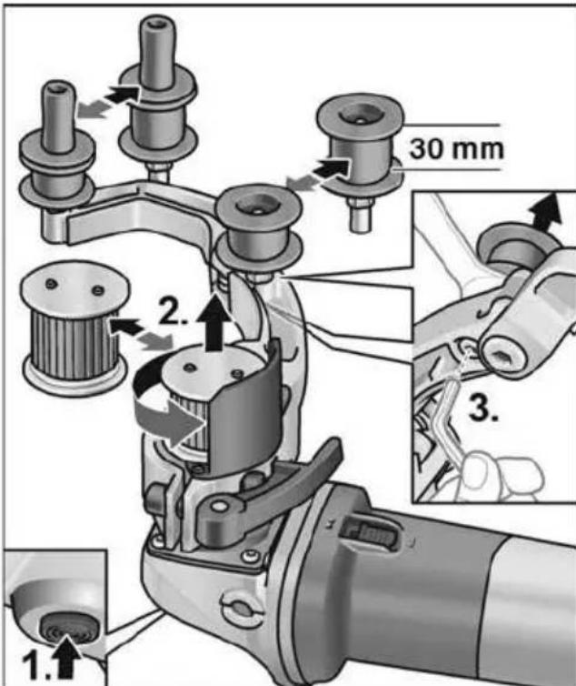
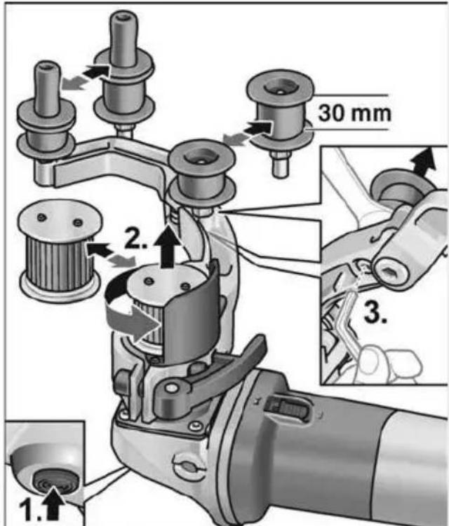
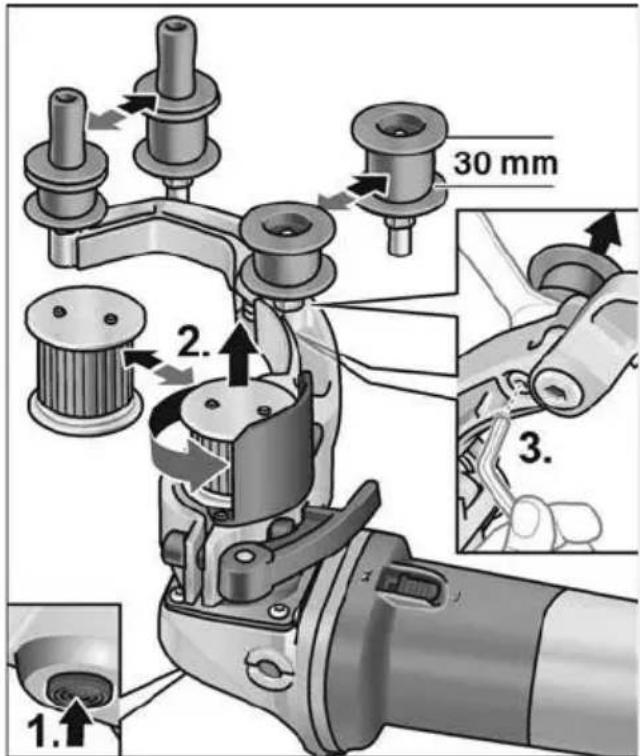
1. 2. 3. 30 mmDrive roller:
■ Press and hold down the spindle lock (1.).
■ Loosen the drive roller against the direction of rotation and pull off (2.).
■ Fit a new drive roller and tighten in direction of rotation.
■ Release spindle lock.
Idler:
■ Loosen bolt using hexagon key and pull off idler (3.).
■ Fit new idler and tighten.
Work instructions for the pipe belt sander attachment

NOTE
When the appliance is switched off, the grinding tool continues running briefly.
A belt sander has the following advantages over a grinding disc:
- cool sanding,
– clean finish without grooves,
– high stock removal rate,
– high productivity on account of large angle of contact (depending on diameter).
Sanding:
i NOTE
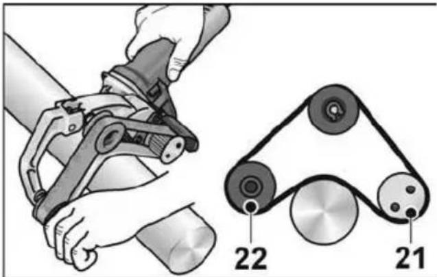
After placing the machine on the workpiece and before switching it on, check that the belt is situated fully on the rollers.
text_image
Diagram showing hands operating a mechanical device with labeled components 21 and 22, alongside a belt drive system diagram.- Pipes are machined between the rollers 21 and 22.
- The angle of contact and the stock removal rate can be varied by the contact pressure.
- The smaller the pipe diameter, the larger the possible angle of contact. Up to 270^ are possible.
Sealing the surface:
Many manufacturers recommend sealing finished surfaces with a protective spray (see Flex stainless steel accessories).
For further information on the manufacturer's products go to www.flex-tools.com.
Belt grinder attachment FBE 8-4
WARNING!
Before performing any work on the electric power tool, pull out the mains plug.
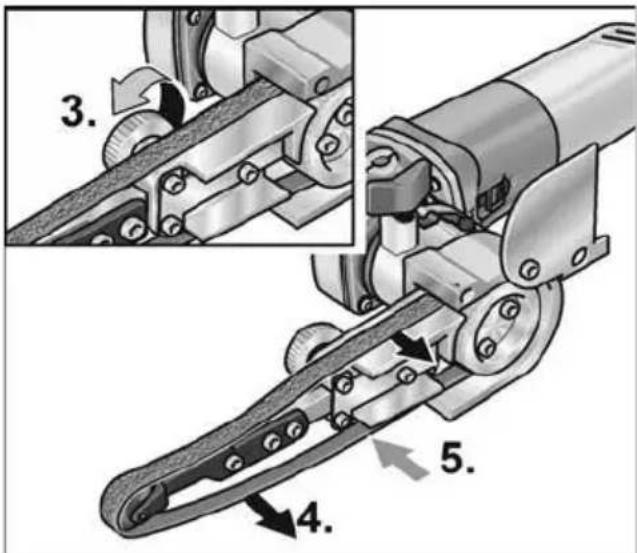
Attaching or changing the sanding belt
■ Pull out the mains plug.
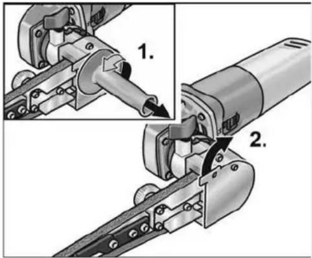
text_image
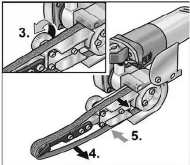
Technical diagram showing mechanical assembly steps with numbered annotations indicating component identification■ Remove handle (1.).
■ Swivel the housing cover to the side (2.).
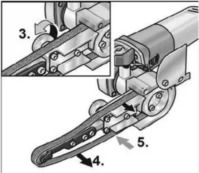
text_image
Technical diagram of a mechanical linkage mechanism with numbered parts and directional arrows indicating motion or assembly.■ Turn eccentric screw and release sanding belt (3.).
■ Remove sanding belt (4.) (optional).
■ Pull on new sanding belt and position centrally on the sanding arm (5.).
■ Tighten sanding belt by turning the eccentric screw.
■ Close housing cover in front of the housing again.
CAUTION!
Observe the specified running direction of the belt! Running direction must correspond with the arrow on the gear head.
Attach the handle
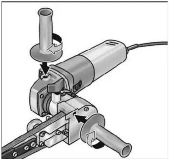
natural_image
Mechanical assembly diagram showing a grinding tool with a cylindrical component and rotating base (no text or symbols)■ Attach the auxiliary handle to the thread in position 1 or 2.
Adjusting the belt run
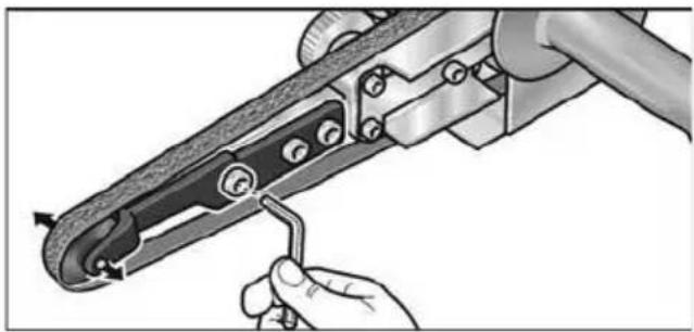
natural_image
Illustration of a hand using a tool to adjust a mechanical component (no text or symbols visible)■ Adjust the belt run using the front screw on the sanding arm. While the belt is running, select the setting so that the belt runs in the centre of the pressure roller.
Changing the sanding arm
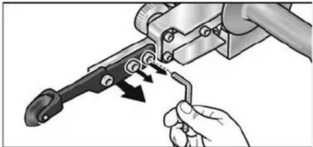
natural_image
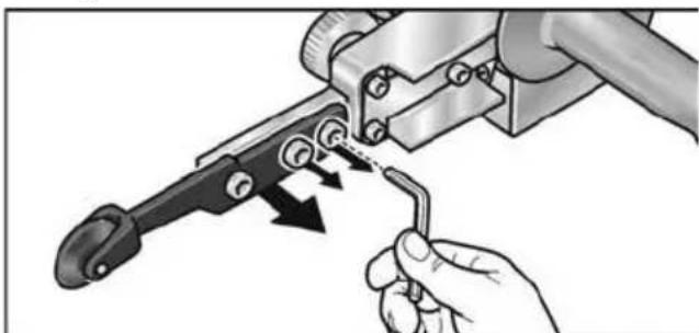
Illustration of a hand using a tool to adjust or install a mechanical component, with arrows indicating motion (no text or symbols present)■ To change the sanding arm, loosen the three fastening screws.
■ Remove sanding arm.
■ Attach new sanding arm using the three screws.
Operating instructions

NOTE
When the electric power tool is switched off, it continues running briefly.
Sanding
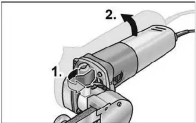
text_image
1. 2.- When the locking screw(1.) is undone, the swivel arm can be tilted up to 140^ (2.). As a result, the belt file can also be used for surfaces which are difficult to access, e.g. the insides of pipes.
■ Vary the removal rate via the contact pressure. Ensure that the contact pressure is even and not too heavy. If the contact pressure is too high, the sanding belt may slip off the roller.
Switching on and off
Brief operation without engaged switch
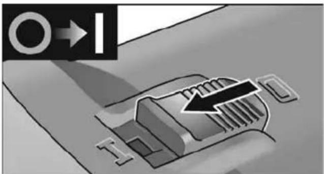
text_image
Diagram showing a mechanical component with directional arrows and text labels, likely illustrating a process or motion path.■ Push the switch rocker forwards and hold in position.
■ To switch off the power tool, release the switch rocker.
Continuous operation with engaged switch
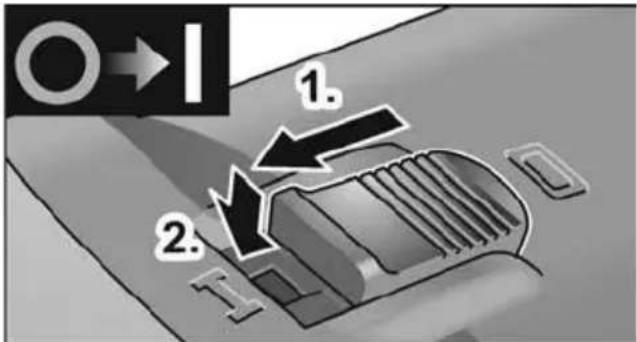
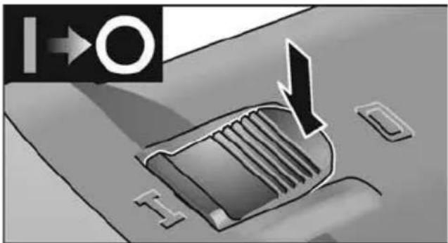
text_image
O→I 1. 2.■ Push the switch rocker forwards (1.) and engage by pressing the front end (2.).
text_image
I→O I O■ To switch off the power tool, release the switch rocker by pressing the rear end.
i NOTE
Following a power failure, the switched on power tool does not restart.
Preselecting the speed
The adjusting wheel enables the operating speed to be continuously adapted to the material requirements.
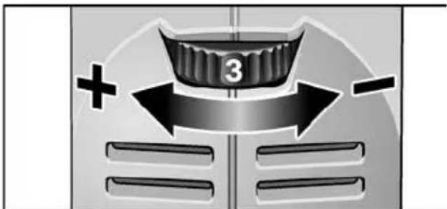
text_image
3 + -| Setting | Speed burnishing attachment [r.p.m.] | Belt speed belt sander attachmentBelt grinder attachment [m/s] |
| 1 | 300 2.7 |
| Setting | Speed burnishing attachment [r.p.m.] | Belt speed belt sander attachment Belt grinder attachment [m/s] |
| 2 | 1600 3.3 | |
| 3 | 2300 4.7 | |
| 4 | 3000 6.3 | |
| 5 | 3500 7.4 | |
| 6 | 3900 8.1 |
Maintenance and care
WARNING!
Before performing any work on the electric power tool, pull out the mains plug.
Cleaning
WARNING!
If metals are ground or cut over a prolonged period, conductive dust may become deposited inside the housing. Impairment of the protective insulation! Operate the power tool via a residual-current-operated circuit-breaker (tripping current 30 mA).
■ Regularly clean the power tool and ventilation slots. Frequency of cleaning is dependent on the material and duration of use.
■ Regularly blow out the housing interior and motor with dry compressed air.
Carbon brushes
The drive unit is fitted with cut-off carbon brushes. When the cut-off carbon brushes reach their wear limit, the power tool switches off automatically.
i NOTE
Use only original parts supplied by the manufacturer for replacement purposes. If non-original parts are used, the guarantee obligations of the manufacturer will be deemed null and void.
When the power tool is being used, the carbon brushes can be seen sparking through the rear air inlet apertures. If the carbon brushes are sparking excessively, switch off the power tool immediately. Take the drive unit to a customer service centre authorised by the manufacturer.
Gears
i NOTE
Do not loosen the screws on the gear head during the warranty period. Non-compliance will deem the guarantee obligations of the manufacturer null and void.
Repairs
Repairs may be carried out by an authorised customer service centre only.
Replacing wearing parts
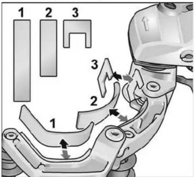
text_image
1 2 3 3 2 1During the operating time of the belt sander the felt pads on the swing arm wear out. Spare parts are available from the manufacturer or your dealer.
Spare parts and accessories
For other accessories, in particular grinding tools, see the manufacturer's catalogues.
Exploded drawings and spare-part lists can be found on our homepage:
www.flex-tools.com
Disposal information
WARNING!
Render redundant power tools unusable by removing the power cord.

EU countries only Do not throw electric power tools into the household waste!
In accordance with the European Directive 2012/19/EU on Waste Electrical and Electronic Equipment and transposition into national law used electric power tools must be collected separately and recycled in an environmentally friendly manner.
NOTE
Please ask your dealer about disposal options!
C ∈-Declaration of Conformity
We declare under our sole responsibility that the product described under “Technical specifications” conforms to the following standards or normative documents:
EN 60745 in accordance with the regulations of the directives 2014/30/EU, 2006/42/EC, 2011/65/EU.
Responsible for technical documents: FLEX-Elektrowerkzeuge GmbH, R & D Bahnhofstrasse 15, D-71711 Steinheim/Murr
Eckhard Rühle Manager Research & Development (R & D)

Klaus Peter Weinper Head of Quality Department (QD)
06.06.2018
Exemption from liability
The manufacturer and his representative are not liable for any damage and lost profit due to interruption in business caused by the product or by an unusable product. The manufacturer and his representative are not liable for any damage which was caused by improper use of the product or by use of the product with products from other manufacturers.
Table des matières
text_image
Technical diagram showing mechanical assembly steps with numbered instructions for tool manipulationtext_image
Technical diagram illustrating three-step mechanical assembly steps with numbered annotationstext_image
Technical diagram showing mechanical assembly steps with numbered annotationstext_image
Technical diagram showing three-step assembly of a mechanical device with labeled parts and directional arrows indicating motion.natural_image
Illustration of a hand using a power tool to cut a surface with directional arrows indicating motion (no text or symbols)natural_image
Mechanical assembly diagram showing a clamping mechanism with three components (no text or labels)text_image
Diagram showing a robotic arm and a belt drive system with labeled components 21 and 22text_image
Technical diagram showing mechanical assembly steps with numbered annotations indicating component identificationtext_image
Technical diagram of a mechanical linkage mechanism with numbered parts and directional arrows indicating motion or assembly.natural_image
Mechanical assembly diagram showing a grinding tool and cutting tool with no visible text or symbolsnatural_image
Illustration of a hand using a tool to adjust or install a mechanical component (no text or symbols visible)natural_image
Illustration of a hand using a tool to adjust or install a mechanical component, with arrows indicating motion (no text or symbols present)text_image
Diagram showing a mechanical component with directional arrows and text labels, likely illustrating a process or motion path.natural_image
Diagram of a vehicle's roof structure with directional arrows and labels (no readable text or symbols)Klaus Peter Weinper Head of Quality Department (QD)
06/06/2018
text_image
Technical diagram showing mechanical assembly steps with numbered instructions for tool manipulationtext_image
Technical diagram illustrating three-step mechanical assembly steps with numbered annotationstext_image
Technical diagram showing mechanical assembly steps with numbered annotations indicating different states or components.text_image
Technical diagram showing three-step assembly of a mechanical device with labeled parts and directional arrows indicating motion.natural_image
Illustration of a hand using a power tool to move on a textured surface with directional arrows indicating motion (no text or symbols)natural_image
Mechanical assembly diagram showing a clamping mechanism with three components and a rotating arrow (no text or symbols)text_image
Diagram showing a robotic arm connecting two pulleys labeled 21 and 22, with a magnified view of the belt system.text_image
Technical diagram showing mechanical assembly steps with numbered annotations indicating component identificationtext_image
Technical diagram of a mechanical linkage mechanism with numbered steps and component viewsnatural_image
Mechanical tool diagram showing a grinding machine with a cylindrical workpiece and rotating shaft (no text or symbols)natural_image
Illustration of a hand using a tool to adjust or install a mechanical component (no text or symbols visible)natural_image
Illustration of a hand using a tool to adjust or install a mechanical component, with arrows indicating motion (no text or symbols present)text_image
Diagram showing a car's side panel with directional arrows and text labels, likely indicating movement or navigation.Klaus Peter Weinper Head of Quality Department (QD)
text_image
Technical diagram showing mechanical assembly steps with numbered instructions for tool manipulationtext_image
Technical diagram illustrating three-step mechanical assembly steps with numbered annotationstext_image
Technical diagram showing three-step assembly of a mechanical device with labeled parts and directional arrows indicating motion.text_image
Diagram showing a car seatbelt being adjusted for a power tool, with numbered instructions for each step.natural_image
Illustration of a hand using a power tool to cut a tire on a textured surface, with directional arrows indicating motion (no text or symbols)natural_image
Mechanical assembly diagram showing a pin roller being inserted into a bracket (no text or symbols)text_image
Diagram showing hands operating a mechanical device with labeled parts 21 and 22, alongside a belt drive system diagram.text_image
Technical diagram showing mechanical assembly steps with numbered annotations indicating component identificationtext_image
Technical diagram of a mechanical linkage mechanism with numbered steps and component viewsnatural_image
Mechanical diagram of a power tool with a cutting tool and connecting rod (no text or symbols)natural_image
Close-up of a hand using a crimping tool to adjust a mechanical component (no text or symbols visible)natural_image
Illustration of a hand using a tool to adjust or install a mechanical component, with arrows indicating motion (no text or symbols present)text_image
Diagram showing a mechanical component with directional arrows and a black arrow pointing to a specific section, labeled '1'.text_image
Technical diagram showing mechanical assembly steps with numbered annotations indicating sequence of componentstext_image
Technical diagram illustrating three-step mechanical assembly steps with numbered annotationstext_image
Technical diagram showing three-step assembly of a mechanical device with labeled parts and directional arrows indicating motion.natural_image
Illustration of a hand using a power tool to cut a textured surface with directional arrows indicating motion (no text or symbols)natural_image
Mechanical assembly diagram showing a pin inserted into a housing component (no text or symbols visible)Substituir os rolos
text_image
30 mm 1. 2. 3.Rolo de acionamento:
text_image
Diagram showing a robotic arm and a belt drive system with labeled parts 21 and 22text_image
Technical diagram showing mechanical assembly steps with numbered annotations indicating component identificationtext_image
Technical diagram of a mechanical linkage mechanism with numbered parts and directional arrows indicating motion or assembly.natural_image
Mechanical assembly diagram showing a grinding tool and tool with no visible text or symbolsnatural_image
Illustration of a hand using a tool to adjust or install a mechanical component (no text or symbols visible)natural_image
Illustration of a hand using a tool to adjust or install a mechanical component, with arrows indicating motion (no text or symbols present)text_image
Diagram showing a mechanical component with directional arrows and text labels, likely illustrating a process or motion path.text_image
Diagram showing a car interior with directional arrows and labels, likely indicating movement or flow direction.EN 60745 de acordo com as determinações das directivas 2014/30/UE, 2006/42/CE, 2011/65/UE.
Klaus Peter Weinper Head of Quality Department (QD)
06/06/2018
text_image
Technical diagram showing mechanical assembly steps with numbered instructions for tool manipulationtext_image
Technical diagram illustrating three-step mechanical assembly steps with numbered annotationstext_image
Technical diagram showing three-step assembly of a mechanical device with labeled parts and directional arrows indicating motion.natural_image
Illustration of a hand using a power tool to cut a tire on a textured surface, with directional arrows indicating motion (no text or symbols)natural_image
Mechanical assembly diagram showing a mechanical component with three circular parts and a central shaft (no text or symbols)Rollen vervangen
text_image
1. 2. 3. 30 mmAandrijfrol:
text_image
Diagram showing hands operating a mechanical device with labeled components 21 and 22, alongside a belt drive system diagram.text_image
Technical diagram showing mechanical assembly steps with numbered annotations indicating component identification■ Handgreep demonteren (1.).
■ De huisafdekking opzij zwenken (2.).
text_image
Technical diagram of a mechanical linkage mechanism with numbered parts and directional arrows indicating motion or assembly.natural_image
Mechanical diagram of a power tool with a cutting tool and connecting rod (no text or symbols)natural_image
Illustration of a hand using a tool to adjust or install a mechanical component (no text or symbols visible)natural_image
Illustration of a hand using a tool to adjust or install a mechanical component, with arrows indicating motion (no text or symbols present)text_image
Diagram showing a mechanical component with directional arrows and text labels, likely illustrating a process or motion path.text_image
I → O I OKlaus Peter Weinper Head of Quality Department (QD)
06-06-2018
text_image
Exploded view diagram of a robotic arm with numbered parts and control panel, likely for assembly or maintenance instructions.Drivenhed BME 8-4
1 Gearhoved
2 Lynkobling til forsatser
3 Vippekontakt
text_image
Technical diagram showing mechanical assembly steps with numbered instructions for tool manipulationtext_image
Technical diagram illustrating three-step mechanical assembly steps with numbered annotationstext_image
Technical diagram showing three steps of a mechanical device with labeled components and directional arrows indicating assembly or operation.■ Løsn låseskruen på forsatsen (1.).
■ Tryk på oplåsningsarmen, og hold den inde (2.).
■ Løft forsatsen af (3.).
natural_image
Illustration of a hand using a power tool to move on a textured surface with directional arrows indicating motion (no text or symbols)natural_image
Mechanical assembly diagram showing a mechanical component with three circular parts and a central shaft (no text or symbols)Skift af ruller
text_image
1. 2. 3. 30 mmDrivrulle:
text_image
Diagram showing hands operating a mechanical device with labeled components 21 and 22, alongside a belt drive system.text_image
Technical diagram showing mechanical assembly steps with numbered annotations indicating component identificationtext_image
Technical diagram of a robotic arm with numbered parts and directional arrows indicating motion or assembly steps.natural_image
Mechanical assembly diagram showing a grinding tool and cutting tool with no visible text or symbolsnatural_image
Close-up of a hand using a tool to adjust or install a mechanical component (no visible text or symbols)natural_image
Illustration of a hand using a tool to adjust a mechanical component (no text or symbols visible)text_image
Diagram showing a mechanical component with directional arrows and a labeled arrow pointing to it, likely indicating movement or force.■ Skub vippekontakten fremad og hold den fast.
■ Slip vippekontakten for at slukke.
natural_image
Close-up of a car's front panel with a directional arrow and logo (no readable text or symbols)Klaus Peter Weinper Head of Quality Department (QD)
06-06-2018
text_image
Technical diagram showing mechanical assembly steps with numbered annotations indicating sequence of componentstext_image
Technical diagram illustrating three-step mechanical assembly steps with numbered annotationstext_image
Technical diagram showing three-step assembly of a mechanical device with labeled parts and directional arrows indicating motion.■ Løsne låseskruen på forsatsen (1.).
■ Trykk på låsespaken, og hold den inntrykt (2.).
■ Løft forsatsen (3.).
Fest fast verktøyet
natural_image
Illustration of a hand using a power tool to move on a textured surface with directional arrows indicating motion (no text or symbols)natural_image
Mechanical assembly diagram showing a mechanical component with three circular parts and a central shaft (no text or symbols)Skifte hjul
text_image
30 mm 1. 2. 3.Drivhjul:
text_image
Diagram showing a robotic arm and a belt drive system with labeled components 21 and 22– Bearbeidingen av rør skjer mellom rullene 21 og 22.
– Omslyngingsvinkelen og slipeeffekten kan varieres med påpresstrykket.
- Jo mindre rørdiameteren er, desto større er den mulige omslyngingsvinkelen. Inntil 270° er mulig.
Seising:
Mange produsenter anbefaler å seise de bearbeidede overflatene med en beskyttelses-spray (se Flex rustfritt stål tilbehør).
text_image
Technical diagram showing mechanical assembly steps with numbered annotations indicating component identificationtext_image
Technical diagram of a mechanical linkage mechanism with numbered parts and directional arrows indicating motion or assembly.natural_image
Mechanical assembly diagram showing a grinding tool with a cylindrical component and rotating base (no text or symbols)natural_image
Illustration of a hand using a tool to adjust or install a mechanical component (no text or symbols visible)natural_image
Illustration of a hand using a tool to adjust or install a mechanical component, with arrows indicating motion (no text or symbols present)■ For skift av slipearmen løsnes de tre festeskruene.
■ Ta av slipearmen.
■ Fest på en ny slipearm med hjelp av de tre skruene.
Arbeidstips
text_image
Diagram showing a mechanical component with directional arrows and a labeled arrow pointing to it, alongside a circular symbol with 'O' and 'I'.text_image
Diagram showing a car interior with directional arrows and labeled parts, likely illustrating vehicle or traffic flow.Klaus Peter Weinper Head of Quality Department (QD)
06.06.2018
text_image
Technical diagram showing mechanical assembly steps with numbered annotations indicating sequence of componentstext_image
Technical diagram illustrating three-step mechanical assembly steps with numbered annotationstext_image
Technical diagram showing mechanical assembly steps with numbered annotationstext_image
Technical diagram showing three-step assembly of a mechanical device with labeled parts and directional arrows indicating motion.natural_image
Illustration of a hand using a power tool to cut a tire on a textured surface, with directional arrows indicating motion (no text or symbols)natural_image
Mechanical assembly diagram showing a pin inserted into a housing with two circular components (no text or symbols)Byta rullar
text_image
30 mm 1. 2. 3.Drivrulle:
text_image
Diagram showing hands operating a mechanical device with labeled components 21 and 22, alongside a belt drive system diagram.text_image
Technical diagram showing mechanical assembly steps with numbered annotations indicating component identificationtext_image
Technical diagram of a robotic arm with numbered parts and directional arrows indicating motion or assembly steps.natural_image
Mechanical assembly diagram showing a grinding tool with a cylindrical component and connecting rods (no text or symbols visible)natural_image
Illustration of a hand using a tool to adjust or install a mechanical component (no text or symbols visible)natural_image
Illustration of a hand using a tool to adjust or install a mechanical component, with arrows indicating motion (no text or symbols present)natural_image
Diagram of a car interior with a directional arrow and control buttons, no readable text or symbols present.Klaus Peter Weinper Head of Quality Department (QD)
2018-06-06
text_image
Technical diagram showing mechanical assembly steps with numbered instructions for tool manipulationtext_image
Technical diagram illustrating three-step mechanical assembly steps with numbered annotationstext_image
Technical diagram showing three steps of a mechanical device with labeled components and directional arrows indicating assembly or operation.natural_image
Illustration of a hand using a power tool to move on a textured surface with directional arrows and a cross symbol (no text or labels)natural_image
Mechanical assembly diagram showing a pin adjustment mechanism with no visible text or symbolsRullien vaihto
text_image
1. 2. 3. 30 mmVetorulla:
text_image
Diagram showing a robotic arm and a belt drive system with labeled components 21 and 22text_image
Technical diagram showing mechanical assembly steps with numbered annotations indicating component identificationtext_image
Technical diagram of a robotic arm with numbered parts and directional arrows indicating motion or assembly steps.natural_image
Mechanical assembly diagram showing a grinding tool with rotating head and cutting edge (no text or symbols)natural_image
Illustration of a hand using a tool to adjust or install a mechanical component (no text or symbols visible)natural_image
Illustration of a hand using a tool to adjust or install a mechanical component, with arrows indicating motion (no text or symbols present)natural_image
Diagram of a vehicle's roof structure with directional arrows and control buttons (no text or symbols)Klaus Peter Weinper Head of Quality Department (QD)
06.06.2018
text_image
Technical diagram showing mechanical assembly steps with numbered annotations indicating sequence of motion or assembly.text_image
Technical diagram illustrating three-step assembly of a mechanical device with labeled parts and directional arrows.text_image
Technical diagram showing three-step assembly of a mechanical device with labeled parts and directional arrows indicating motion.text_image
Technical diagram illustrating mechanical assembly steps with numbered instructions and labeled componentsnatural_image
Illustration of a hand using a power tool on a textured surface with directional arrows indicating motion (no text or symbols)natural_image
Mechanical assembly diagram showing a pin roller being inserted into a bracket (no text or symbols)Αλλαγή κυλίνδρων
text_image
1. 2. 3. 30 mmtext_image
Diagram showing hands operating a robotic device connected to a belt drive system with labeled parts 21 and 22text_image
Technical diagram showing mechanical assembly steps with numbered annotations indicating component identificationtext_image
Technical diagram of a robotic arm with numbered parts and directional arrows indicating motion or assembly steps.natural_image
Mechanical assembly diagram of a power tool with a cylindrical component and connecting rod (no text or symbols visible)natural_image
Close-up of hands using a mechanical tool to adjust or install a component (no visible text or symbols)natural_image
Illustration of a hand using a tool to adjust or install a mechanical component, with arrows indicating process flow (no text or symbols present)text_image
Diagram showing a mechanical component with directional arrows and labels, likely illustrating a process or motion path.text_image
Diagram showing a car interior with directional arrows and labels, likely indicating movement or flow direction.Klaus Peter Weinper
Head of Quality
Department (QD)
06/06/2018
text_image
Technical diagram showing mechanical assembly steps with numbered instructions for tool manipulationtext_image
Technical diagram illustrating three-step mechanical assembly steps with numbered annotationstext_image
Technical diagram showing mechanical assembly steps with numbered annotationstext_image
Technical diagram showing three-step assembly of a mechanical device with labeled parts and directional arrows indicating motion.natural_image
Illustration of a hand using a power tool on a textured surface with directional arrows indicating motion (no text or symbols)natural_image
Mechanical assembly diagram showing a mechanical component with three circular parts and a central shaft (no text or symbols)text_image
Diagram showing a hand operating a mechanical device with a belt drive system labeled 21 and 22text_image
Technical diagram showing mechanical assembly steps with numbered annotations indicating component identificationtext_image
Technical diagram of a mechanical linkage mechanism with numbered parts and directional arrows indicating motion or assembly.natural_image
Mechanical diagram of a power tool with a cutting tool and blade assembly (no text or symbols)natural_image
Illustration of a hand using a tool to adjust or install a mechanical component (no text or symbols visible)natural_image
Illustration of a hand using a tool to adjust or install a mechanical component, with arrows indicating motion (no text or symbols present)text_image
Diagram showing a mechanical component with directional arrows and text labels, likely illustrating a process or motion path.text_image
I→O D I Otext_image
Technical diagram showing mechanical assembly steps with numbered instructions for tool manipulationtext_image
Technical diagram illustrating three-step assembly steps of a mechanical device, labeled 1 to 3 with numbered annotations.text_image
Technical diagram showing three-step assembly of a mechanical device with labeled parts and directional arrows indicating motion.natural_image
Illustration of a hand using a power tool to cut a tire on a textured surface, with directional arrows indicating motion (no text or symbols)natural_image
Mechanical assembly diagram showing a clamping mechanism with three components (no text or labels)Wymiana rolek
text_image
1. 2. 3. 30 mmRolka napędowa:
text_image
Diagram showing hands operating a mechanical device with labeled components 21 and 22, alongside a belt drive system diagram.text_image
Technical diagram showing mechanical assembly steps with numbered annotations indicating component identificationtext_image
Technical diagram of a mechanical linkage mechanism with numbered parts and directional arrows indicating motion or assembly.natural_image
Mechanical assembly diagram showing a grinding tool and cutting tool with no visible text or symbolsnatural_image
Close-up of a hand using a tool to adjust or install a mechanical component (no visible text or symbols)natural_image
Illustration of a hand using a tool to adjust a mechanical component with arrows indicating motion (no text or symbols present)text_image
Diagram showing a 3D mechanical component with directional arrows and text labels, likely illustrating a process or assembly.natural_image
Diagram of a car interior with a vehicle and directional arrow, no readable text or symbols present.Klaus Peter Weinper Head of Quality Department (QD)
text_image
Technical diagram showing mechanical assembly steps with numbered annotations indicating sequence of componentstext_image
Technical diagram illustrating three-step mechanical assembly steps with numbered annotationstext_image
Technical diagram showing three-step assembly of a mechanical device with labeled parts and directional arrows indicating motion.natural_image
Illustration of a hand using a power tool to cut a surface with directional arrows indicating motion (no text or symbols)natural_image
Mechanical assembly diagram showing a pin inserted into a housing component (no text or symbols)Görgőcsere
text_image
1. 2. 3. 30 mmMeghajtógörgő:
text_image
Diagram showing a robotic arm and a pulley system with labeled parts 21 and 22text_image
Technical diagram showing mechanical assembly steps with numbered annotations indicating component identificationtext_image
Technical diagram of a mechanical linkage system with numbered components and directional arrows indicating motion or assembly.natural_image
Mechanical assembly diagram showing a grinding tool with rotating head and connecting rod (no text or symbols)natural_image
Illustration of a hand using a tool to adjust or install a mechanical component (no text or symbols visible)natural_image
Illustration of a hand using a tool to adjust or install a mechanical component, with arrows indicating motion (no text or symbols present)text_image
Diagram showing a mechanical component with directional arrows and a black arrow pointing to a specific section, labeled with symbols like 'O' and 'I'.text_image
Diagram showing a car interior with directional arrows and a lightning bolt symbol, likely indicating movement or flow.Klaus Peter Weinper Head of Quality Department (QD)
text_image
Technical diagram showing mechanical assembly steps with numbered annotations indicating sequence of componentstext_image
Technical diagram illustrating three-step mechanical assembly steps with numbered annotationstext_image
Technical diagram illustrating three-step mechanical assembly steps with labeled components and directional arrowsnatural_image
Illustration of a hand using a power tool to move on a textured surface with directional arrows indicating motion (no text or symbols)natural_image
Mechanical assembly diagram showing a pin roller being inserted into a housing (no text or symbols)Výměna válečků
text_image
30 mm 1. 2. 3.Hnací váleček:
text_image
Diagram showing hands operating a mechanical device with labeled components 21 and 22, alongside a belt drive system.text_image
Technical diagram showing mechanical assembly steps with numbered annotations indicating component identificationtext_image
Technical diagram of a robotic arm with numbered parts and directional arrows indicating motion or assembly steps.natural_image
Mechanical diagram of a power tool with a cutting tool and connecting rod (no text or symbols)natural_image
Close-up of a hand using a tool to adjust or install a mechanical component (no visible text or symbols)natural_image
Illustration of a hand using a tool to adjust or install a mechanical component, with arrows indicating motion (no text or symbols present)text_image
Diagram showing a mechanical component with directional arrows and text labels, likely illustrating a process or motion path.natural_image
Diagram of a car interior showing a vehicle with a directional arrow and control buttons (no text or symbols)Klaus Peter Weinper Head of Quality Department (QD)
06.06.2018
text_image
Technical diagram showing mechanical assembly steps with numbered annotations indicating sequence of components■ Otvorte upínaciu páčku na nadstavci (1.).
■ Hnaciu jednotku nasadte v požadovanej polohe k nadstavcu a zatlačte nadol tak, aby počutelne zapadla (2.).
■ Zatvorte upínaciu páčku (3.).
text_image
Technical diagram illustrating three-step mechanical assembly steps with numbered annotationstext_image
Technical diagram showing three-step assembly of a mechanical device with labeled parts and directional arrows indicating motion.■ Uvoľnite aretačnú skrutku na nadstavci (1.).
■ Stlačte odblokovaciu páčku a držte ju stlačenú (2.).
■ Zdvihnite nadstavec (3.).
Upevnenie nástroja
natural_image
Illustration of a hand using a power tool to move on a textured surface with directional arrows indicating motion (no text or symbols)■ Nasad'te elektrické náradie opatrne na opracovávaný povrch a pohybujte náradím lineárnymi pohybmi dopredu a naspät'.
natural_image
Mechanical assembly diagram showing a clamping mechanism with pulleys and a shaft (no text or symbols)Výmena kladky
text_image
30 mm 1. 2. 3.Hnacia kladka:
text_image
Diagram showing a hand operating a mechanical device with a belt drive system labeled 21 and 22text_image
Technical diagram showing mechanical assembly steps with numbered instructions for tool manipulation■ Demontujte rukovät' (1.).
■ Odklopte kryt telesa náradia na stranu (2.).
text_image
Technical diagram of a robotic arm with numbered parts and directional arrows indicating motion or assembly steps.natural_image
Mechanical assembly diagram showing a grinding tool with a cylindrical component and rotating base (no text or symbols)natural_image
Illustration of a hand using a tool to adjust or install a mechanical component (no text or symbols visible)natural_image
Illustration of a hand using a tool to adjust or install a mechanical component (no text or symbols visible)Klaus Peter Weinper Head of Quality Department (QD)
06.06.2018
text_image
Technical diagram showing mechanical assembly steps with numbered annotations indicating sequence of components■ Otvorite polugu za zatezanje na nastavku (1.).
■ Pogonsku jedinicu postavite u željeni položaj na nastavak i pritišćite prema dolje dok čujno ne uskoči (2.).
■ Zatvorite polugu za zatezanje (3.).

NAPUTAK
Ozupčenja brze spojke pogonske jedinice i nastavka automatski se spajaju prilikom uključivanja.
text_image
Technical diagram illustrating three-step mechanical assembly steps with numbered annotations■ Otpustite vijak za fiksiranje (1.).
■ Pogonsku jedinicu stavite na brzu spojku (2.).
■ Ponovno pritegnite vijak za zaključavanje (3.).
Demontaža nastavaka
text_image
1. 2. 3.■ Otvorite polugu za zatezanje na nastavku (1.).
■ Pritisnite polugu za deblokadu i čvrsto ju držite (2.).
■ Skinite pogonsku jedinicu sa nastavka (3.).
text_image
Technical diagram showing three steps of a mechanical device with labeled components and directional arrows indicating assembly or operation.■ Otpustite vijak za fiksiranje na nastavku (1.).
■ Pritisnite polugu za deblokadu i držite je pritisnutu (2.).
■ Podignite nastavak (3.).
text_image
Technical diagram illustrating a mechanical assembly with numbered steps and component details, including a knob and gear mechanism.■ Alat odn. nosač alata gurnite u prihvat alata (opruga utora za podešavanje oblika) (2.).
natural_image
Illustration of a hand using a power tool to move on a textured surface with directional arrows indicating motion (no text or symbols)natural_image
Mechanical assembly diagram showing a mechanical component with three circular parts and a curved arrow indicating rotation (no text or symbols)Zamjena valjaka
text_image
1. 2. 3. 30 mmPogonski valjak:
■ Pritisnite blokadu vretena i držite je pritisnutu (1.).
■ Otpustite pogonski valjak u smjeru suprotnom od kazaljke na satu i izvucite ga (2.).
■ Stavite novi pogonski valjak i okrenite u smjeru kazaljke na satu.
■ Otpustite blokadu vretena.
Zakretni valjak:
■ Vijak otpustite imbus ključem i izvucite zakretni valjak (3.).
■ Stavite novi zakretni valjak i zategnite.
Upute za rad nastavka trakaste brusilice za cijevi

OPREZ!
text_image
Diagram showing a hand operating a mechanical device with a belt drive system labeled 21 and 22text_image
Technical diagram showing mechanical assembly steps with numbered annotations indicating component identificationtext_image
Technical diagram of a mechanical linkage mechanism with numbered parts and directional arrows indicating motion or assembly.■ Ekscentrični vijak okrenite i tako otpustite brusnu traku (3.).
■ Skinite brusnu traku (4.) (opcionalno).
■ Navucite novu brusnu traku na sredinu brusne ruke (5.).
■ Brusnu traku zategnite okretanjem ekscentričnog vijka.
■ Pokrov kućišta ponovno zaklopite na kućište.

OPREZ!
natural_image
Mechanical assembly diagram showing a grinding tool with rotating head and connecting rod (no text or symbols)■ Dodatnu ručku pričvrstite na navoj u položaj 1 ili 2.
natural_image
Close-up of a hand using a tool to adjust or install a mechanical component (no text or symbols visible)■ Pomoću prednjeg vijka na brusnoj ruci namjestite kretanje trake. Kad se traka kreće, postavku odaberite tako da traka prolazi u sredini preko potisnog valjka.
Zamjena brusne ruke
natural_image
Illustration of a hand using a tool to adjust or install a mechanical component, with arrows indicating process flow (no text or symbols present)■ Za zamjenu brusne ruke popustite tri pričvrsna vijka.
■ Skinite brusnu ruku.
■ Pomoću tri vijka pričvrstite novu brusnu ruku.
Upute za rad

NAPUTAK
text_image
Diagram showing a mechanical component with directional arrows and symbols, likely illustrating a process or motion path.natural_image
Diagram of a car interior showing a vehicle seat with a directional arrow indicating flow (no text or symbols)■ Radi isključivanja ozibnu sklopku deblokirati pritiskom na zadnji kraj.
i NAPUTAK
Nakon nestanka struje uključeni se aparat ne pokreće ponovno.
Odabir broja okretaja
Manager Research & Development (R & D)

Klaus Peter Weinper Head of Quality Department (QD)
06.06.2018
natural_image
Four gray circular icons with human, person, glasses, and a QR code symbol (no text or labels)text_image
Technical diagram showing mechanical assembly steps with numbered annotations indicating sequence of components.text_image
Technical diagram illustrating three-step mechanical assembly steps with numbered annotationstext_image
Technical diagram showing three steps of a mechanical device with labeled components and directional arrows indicating assembly or operation.■ Sprostite pritrdilni vijak na nastavku (1.).
■ Pritisnite ročico za odklop in jo držite pritisnjeno (2.).
■ Dvignite nastavek (3.).
Pritrditev nastavka
Vpenjalo omogoča menjavo nastavkov brez pribora.
■ Izvlecite vtič iz vtičnice.
■ Pritisnite in držite zaporo vretena (1.).
text_image
1. 2. 3. 4.■ Nastavek oz. nosilec nastavka namestite na vpenjalo (vez utora in peresa) (2.).
■ Nastavek potisnite proti vzmeti navzdol (3.) in ga obrnite v smeri urnega kazalca (4.). Vpenjalo je zataknjeno.
i OPOMBA
text_image
Diagram showing two steps of car wheel riming: step 1 indicates clockwise shift, step 2 indicates reverse shift.■ Ponovno zategnite pritrdilni vijak.
natural_image
Illustration of a hand using a power tool to move on a textured surface with directional arrows indicating motion (no text or symbols)■ Električno orodje previdno postavite na površino, ki jo želite obdelati, in ga z vzporednimi pomiki premikajte naprej in nazaj.
Priključek tračnega brusilnika cevi BRE 8-4
OPOZORILO!
natural_image
Mechanical assembly diagram showing a clamping mechanism with no visible text or symbolsZamenjava valjev
text_image
1. 2. 3. 30 mmPogonski valj:
■ Pritisnite in držite zaporo vretena (1.).
■ Pogonski valj sprostite tako, da ga zavrtite v levo in ga snamete (2.).
■ Namestite nov pogonski valj in ga pritrdite tako, da ga zavrtite v desno.
■ Izpustite zaporo vretena.
text_image
Diagram showing a robotic arm and a belt drive system with labeled components 21 and 22text_image
Technical diagram showing mechanical assembly steps with numbered annotations indicating component identificationtext_image
Technical diagram of a robotic arm with numbered parts and directional arrows indicating motion or assembly steps.■ Zavrtite ekscentrični vijak, da sprostite brusilni trak (3.).
■ Snemite brusilni trak (4.) (dodatna oprema).
■ Na sredino brusilne roke namestite nov brusilni trak (5.).
■ Zavrtite ekscentrični vijak, da napnete brusilni trak.
■ Pokrov ohišja znova nataknite na ohišje.
POZOR!
natural_image
Mechanical assembly diagram showing a grinding tool with a cylindrical component and rotating base (no text or symbols)natural_image
Illustration of a hand using a tool to adjust or install a mechanical component (no text or symbols visible)natural_image
Illustration of a hand using a tool to adjust or install a mechanical component, with arrows indicating motion (no text or symbols present)■ Za menjavo brusilne roke sprostite tri pritrdilne vijake.
■ Snemite brusilno roko.
■ S tremi vijaki pritrdite novo brusilno roko.
Navodila za delo
i OPOMBA
natural_image
Diagram of a car interior with a directional arrow and control buttons, no readable text or symbols present.■ Za izklop pritisnite na zadnji del prekucnega stikala, tako da sprostite zaporo.
i OPOMBA
Klaus Peter Weinper Head of Quality Department (QD)
06.06.2018
text_image
Technical diagram showing mechanical assembly steps with numbered instructions for tool manipulationtext_image
Technical diagram illustrating three-step mechanical assembly steps with numbered annotationstext_image
Technical diagram showing mechanical assembly steps with numbered annotationstext_image
Technical diagram showing three-step assembly of a mechanical device with labeled parts and directional arrows indicating motion.natural_image
Illustration of a hand using a power tool to cut a mechanical component, with directional arrows indicating motion (no text or symbols)natural_image
Mechanical assembly diagram showing a clamping mechanism with three components (no text or labels)Înlocuirea rolelor
text_image
1. 2. 3. 30 mmRola de actionare:
text_image
Diagram showing a hand operating a mechanical device with a pulley system labeled 21 and 22, alongside a close-up of the device.text_image
Technical diagram showing mechanical assembly steps with numbered annotations indicating component identificationtext_image
Technical diagram of a mechanical linkage mechanism with numbered parts and directional arrows indicating motion or assembly.natural_image
Mechanical assembly diagram showing a grinding tool and cutting tool with no visible text or symbolsnatural_image
Close-up of a hand using a tool to adjust or install a mechanical component (no visible text or symbols)natural_image
Illustration of a hand using a tool to adjust or install a mechanical component, with arrows indicating motion (no text or symbols present)text_image
Diagram showing a car interior with directional arrows and labeled parts, likely illustrating vehicle or traffic flow.EN 60745 conform prevederilor Directivei 2014/30/UE, 2006/42/CE, 2011/65/UE.
Responsabili pentru documente tehnice: FLEX-Elektrowerkzeuge GmbH, R & D Bahnhofstrasse 15, D-71711 Steinheim/Murr
Eckhard Rühle Manager Research & Development (R & D)

Klaus Peter Weinper Head of Quality Department (QD)
text_image
Technical diagram showing mechanical assembly steps with numbered annotations indicating sequence of motion or movement.text_image
Technical diagram illustrating three-step mechanical assembly steps with numbered annotationstext_image
Technical diagram showing three-step assembly of a mechanical device with labeled parts and directional arrows indicating motion.natural_image
Illustration of a hand using a power tool to cut a surface with directional arrows indicating motion (no text or symbols)natural_image
Mechanical assembly diagram showing a pin inserted into a housing component (no text or symbols)Смяна на ролките
text_image
1. 2. 3. 30 mmЗадвижваща ролка:
text_image
Diagram showing a robotic arm and a pulley system with labeled parts 21 and 22text_image
Technical diagram showing mechanical assembly steps with numbered annotations indicating component identificationtext_image
Technical diagram of a mechanical device with numbered parts and directional arrows indicating motion or assembly steps.natural_image
Mechanical diagram of a power tool with a rotating head and connecting rod (no text or symbols)natural_image
Illustration of a hand using a tool to adjust or install a mechanical component (no text or symbols visible)natural_image
Illustration of a hand using a tool to adjust a mechanical component with arrows indicating motion (no text or symbols present)text_image
Diagram showing a mechanical component with directional arrows and a labeled arrow pointing to it, likely indicating motion or flow.text_image
Diagram showing a car interior with directional arrows and labels, likely indicating movement or flow direction.Klaus Peter Weinper Head of Quality Department (QD)
06.06.2018
text_image
Exploded view diagram of a robotic arm with numbered parts and control panel, likely for assembly or maintenance instructions.text_image
Technical diagram showing mechanical assembly steps with numbered annotations indicating sequence of componentstext_image
Technical diagram illustrating three-step mechanical assembly steps with numbered annotationstext_image
Technical diagram showing mechanical assembly steps with numbered annotationstext_image
Technical diagram showing three steps of a mechanical device assembly with labeled components and directional arrows.natural_image
Illustration of a hand using a power tool to cut a tire on a textured surface, with directional arrows indicating motion (no text or symbols)natural_image
Mechanical assembly diagram showing a clamping mechanism with pulleys and a shaft (no text or symbols)Замена роликов
text_image
30 mm 1. 2. 3.Приводной ролик:
text_image
Diagram showing a robotic arm and a pulley system with labeled parts 21 and 22text_image
Technical diagram showing mechanical assembly steps with numbered annotations indicating component identificationtext_image
Technical diagram of a robotic arm with numbered parts and directional arrows indicating motion or assembly steps.natural_image
Mechanical assembly diagram showing a grinding tool with a cylindrical component and rotating shaft (no text or symbols)natural_image
Illustration of a hand using a tool to adjust or install a mechanical component (no text or symbols visible)natural_image
Illustration of a hand using a tool to adjust or install a mechanical component, with arrows indicating process flow (no text or symbols present)text_image
Diagram showing a mechanical component with directional arrows and a labeled arrow pointing to it, likely indicating motion or flow.text_image
Diagram showing a vehicle interior with directional arrows and labels, likely indicating movement or flow direction.Klaus Peter Weinper Head of Quality Department (QD)
06.06.2018
text_image
Technical diagram showing mechanical assembly steps with numbered instructions for tool manipulationtext_image
Technical diagram illustrating three-step mechanical assembly steps with numbered annotationstext_image
Technical diagram showing three-step assembly of a mechanical device with labeled parts and directional arrows indicating motion.natural_image
Illustration of a hand using a power tool to move on a textured surface with directional arrows indicating motion (no text or symbols)natural_image
Mechanical assembly diagram showing a mechanical component with three parts and a directional arrow indicating motion (no text or symbols)Rullide vahetamine
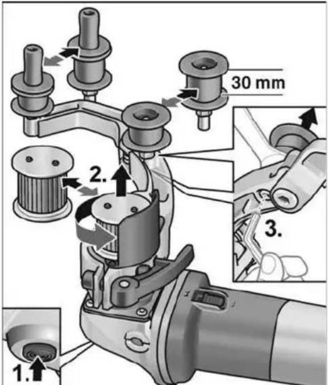
text_image
30 mm 1. 2. 3.Veorull:
text_image
Diagram showing a robotic arm and a pulley system with labeled components 21 and 22text_image
Technical diagram showing mechanical assembly steps with numbered instructions for tool manipulationtext_image
Technical diagram of a mechanical device with numbered parts and directional arrows indicating motion or assembly steps.natural_image
Mechanical assembly diagram showing a grinding tool with rotating head and connecting rod (no text or symbols)natural_image
Illustration of a hand using a tool to adjust or install a mechanical component (no text or symbols visible)natural_image
Illustration of a hand using a tool to adjust or install a mechanical component, with arrows indicating motion (no text or symbols present)text_image
Diagram showing a mechanical component with directional arrows and symbols, likely illustrating a process or motion path.natural_image
Diagram of a car interior showing airflow direction and valve placement (no text or symbols)Klaus Peter Weinper Head of Quality Department (QD)
06.06.2018
text_image
Technical diagram showing mechanical assembly steps with numbered instructions for tool manipulationtext_image
Technical diagram illustrating three-step mechanical assembly steps with numbered annotationstext_image
Technical diagram showing mechanical assembly steps with numbered annotationstext_image
Technical diagram illustrating three-step mechanical assembly steps with labeled components and directional arrowsnatural_image
Illustration of a hand using a power tool to move on a textured surface with directional arrows indicating motion (no text or symbols)natural_image
Mechanical assembly diagram showing a pin inserted into a housing with two washers (no text or symbols)Ritinėlių keitimas
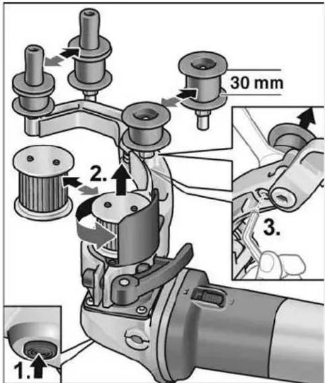
text_image
1. 2. 3. 30 mmVarantysis ritinélis:
text_image
Diagram showing a robotic arm and a pulley system with labeled parts 21 and 22text_image
Technical diagram showing mechanical assembly steps with numbered annotations indicating component identificationtext_image
Technical diagram of a robotic chain assembly with numbered parts and directional arrows indicating motion or assembly steps.natural_image
Mechanical assembly diagram showing a grinding tool and cutting tool with no visible text or symbolsnatural_image
Illustration of a hand using a tool to adjust or install a mechanical component (no text or symbols visible)natural_image
Illustration of a hand using a manual tool to adjust or install a mechanical component, with arrows indicating motion (no text or symbols present)Manager Research & Development (R & D)

Klaus Peter Weinper
Head of Quality Department (QD)
06.06.2018
text_image
Technical diagram showing mechanical assembly steps with numbered annotations indicating sequence of componentstext_image
Technical diagram illustrating three-step mechanical assembly steps with numbered annotationstext_image
Technical diagram showing three-step assembly of a mechanical device with labeled parts and directional arrows indicating motion.natural_image
Illustration of a hand using a power tool to move on a textured surface with directional arrows indicating motion (no text or symbols)natural_image
Mechanical assembly diagram showing a clamping mechanism with three components (no text or labels)Rullīšu nomaina
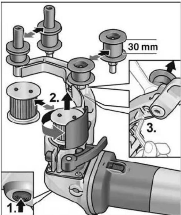
text_image
30 mm 1. 2. 3.Piedziñas rullitis:
text_image
Diagram showing hands operating a mechanical device with labeled components 21 and 22, alongside a belt drive system diagram.text_image
Technical diagram showing mechanical assembly steps with numbered annotations indicating component identificationtext_image
Technical diagram of a mechanical linkage mechanism with numbered parts and directional arrows indicating motion or assembly.natural_image
Mechanical assembly diagram showing a power tool and connecting rod (no text or symbols visible)natural_image
Illustration of a hand using a tool to adjust or install a mechanical component (no text or symbols visible)natural_image
Illustration of a hand using a tool to adjust or install a mechanical component, with arrows indicating motion (no text or symbols present)text_image
Diagram showing a mechanical component with directional arrows and a black arrow pointing to a specific section, labeled with symbols like 'O' and 'I'.natural_image
Diagram of a vehicle's seatbelt with directional arrow and logo (no text or symbols)Klaus Peter Weinper Head of Quality Department (QD)
06.06.2018
text_image
Rille Bohn D.1Eckhard Rühle
Manager Research &
Development (R & D)
Klaus Peter Weinper
Head of Quality
Department (QD)
natural_image
Diagram of a vehicle battery with a lightning bolt symbol, no readable text or labels presenttext_image
Diagram showing a 3D mechanical component with directional arrows and symbols, likely illustrating a process or assembly.natural_image
Mechanical assembly diagram showing a grinding tool with a cylindrical component and a cutting tool (no text or symbols visible)natural_image
Illustration of a hand using a tool to adjust or install a mechanical component (no text or symbols visible)natural_image
Illustration of a hand using a tool to adjust or install a mechanical component, with arrows indicating process flow (no text or symbols present)text_image
Technical diagram showing mechanical assembly steps with numbered annotations indicating component identification(1) اخlegg المبيض
text_image
Technical diagram of a mechanical linkage mechanism with numbered parts and directional arrows indicating motion or assembly.text_image
Diagram showing a hand operating a mechanical device with a pulley system, labeled with parts 21 and 22.natural_image
Mechanical assembly diagram showing a mechanical component with three parts and a central shaft (no text or symbols)تغيير البكرات
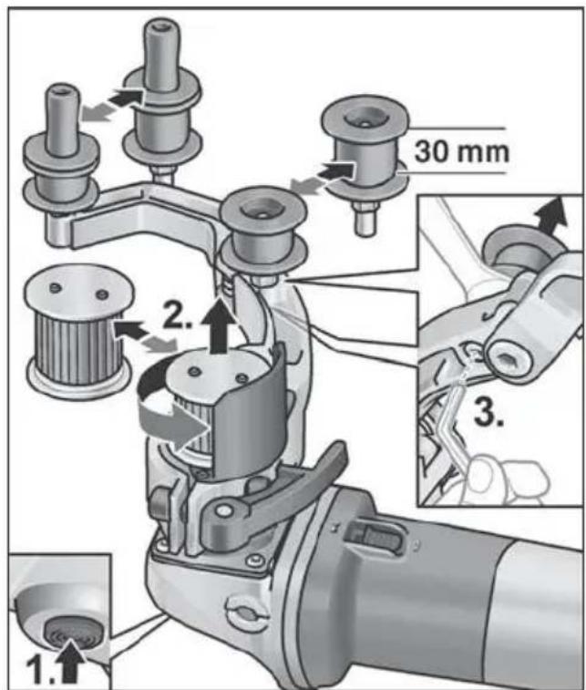
text_image
30 mm 1. 2. 3.بكرة الإدارة:
natural_image
Illustration of a hand using a power tool to cut a circular object on a textured surface, with directional arrows indicating motion (no text or symbols)text_image
Technical diagram showing two steps of a tool manipulation process: step 1 (cutting part) and step 2 (cutting edge)text_image
Technical diagram of a mechanical device with numbered parts and an inset showing a close-up view of internal components.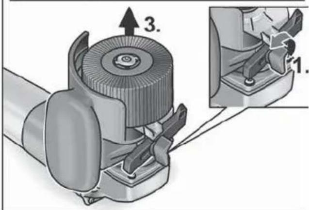
text_image
3. 1.text_image
Technical diagram illustrating three-step mechanical assembly steps with numbered annotationstext_image
Technical diagram showing mechanical assembly steps with numbered annotationstext_image
Technical diagram showing mechanical assembly steps with numbered instructions for tool manipulationFBE 8-4 الم parties shrimpي