WSSE12 - Speaker stands SANUS - Free user manual and instructions
Find the device manual for free WSSE12 SANUS in PDF.

User questions about WSSE12 SANUS
0 question about this device. Answer the ones you know or ask your own.
Ask a new question about this device
Download the instructions for your Speaker stands in PDF format for free! Find your manual WSSE12 - SANUS and take your electronic device back in hand. On this page are published all the documents necessary for the use of your device. WSSE12 by SANUS.
USER MANUAL WSSE12 SANUS
natural_image
Line drawing of a simple cylindrical object with a base, resembling a table or stand (no text or symbols)We'll Make It Stress-Free
If you have any questions along the way, just give us a call.
US: +1 (800) 359-5520 · EMEA: +31 (0) 495 580 852 · UK: +44 (0) 800 056 2853
We're ready to help!
IMPORTANT SAFETY INSTRUCTIONS
— PLEASE READ ENTIRE MANUAL PRIOR TO USE — SAVE THESE INSTRUCTIONS
Before getting started, let's make sure this product is perfect for you!
This stand is designed to support only Sonos® Era 100™ speakers.
CAUTION: Avoid potential personal injuries and property damage!
- Check your speaker owner's manual to see if there are any special requirements for mounting your speaker.
- Please read through these instructions completely to be sure you're comfortable with this easy install process.
- Do not use this product for any purpose not explicitly specified by manufacturer.
- Manufacturer is not responsible for damage or injury caused by incorrect assembly or use.
- If you do not understand these instructions or have doubts about the safety of the installation, assembly or use of this product, contact Customer Service at US: +1 (800) 359-5520 · EMEA: +31 (0) 495 580 852 · UK: +44 (0) 800 056 2853.
Speaker Weight Limit
DO NOT EXCEED

text_image
5 lbs. (2.2 kg)Tool Needed

Screwdriver
Dimensions
TOP VIEW
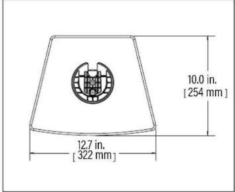
text_image
10.0 in. [254 mm] 12.7 in. [322 mm]FRONT VIEW
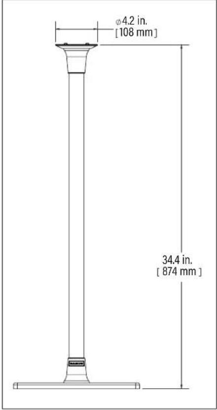
text_image
φ4.2 in. [108 mm] 34.4 in. [ 874 mm ]SIDE VIEW
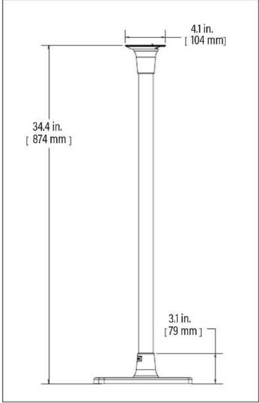
text_image
4.1 in. [ 104 mm ] 34.4 in. [ 874 mm ] 3.1 in. [ 79 mm ]3D
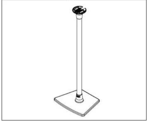
natural_image
Line drawing of a pole with a square base and circular top (no text or symbols)Parts and Hardware
⚠ WARNING: This product contains small items that could be a choking hazard if swallowed.
Before starting assembly, verify all parts are included and undamaged. If any parts are missing or damaged, do not return the damaged item to your dealer; contact Customer Service. Never use damaged parts!

NOTE: Not all hardware included will be used.
Quantities shown are for one speaker stand.
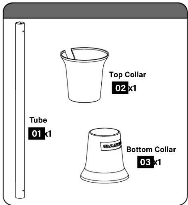
text_image
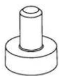
Top Collar 02 x1 Tube 01 x1 Bottom Collar 03 x1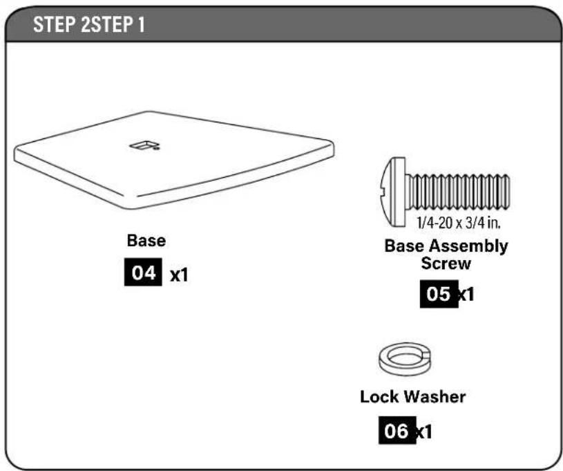
text_image
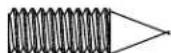
STEP 2STEP 1 Base 04 x1 1/4-20 x 3/4 in. Base Assembly Screw 05 x1 Lock Washer 06 x1STEP 4
Rubber Pad
07 x4
OPTIONAL
M6x20mm
Carpet Spike
08 x4

M6
Jam Nut
09 x4
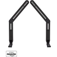
STEP 5
Top Bracket
10 x1
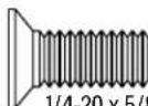
1/4-20 x 5/8 in.
Top Bracket Screw
11 k1
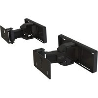
STEP 6
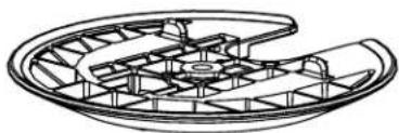
natural_image
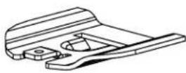
Technical line drawing of a mechanical component with internal grid structure (no text or symbols)Speaker Bracket
12 x1
M5 x 14mm
Speaker Screw
13 k1
STEP 7

10-24 x 3/8 in.
Securement Screw
14 x1
STEP 1
Slide Collars onto Tube
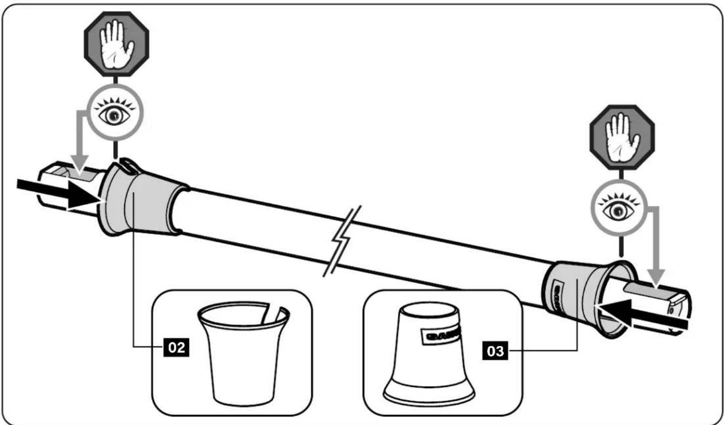
flowchart
graph TD
    A["Hand"] --> B["Eye"]
    B --> C["Hand"]
    D["Hand"] --> E["Eye"]
    E --> F["Hand"]
    G["02"] --> H["Teaker"]
    I["03"] --> J["Teaker"]
STEP 2
Attach Base to Tube
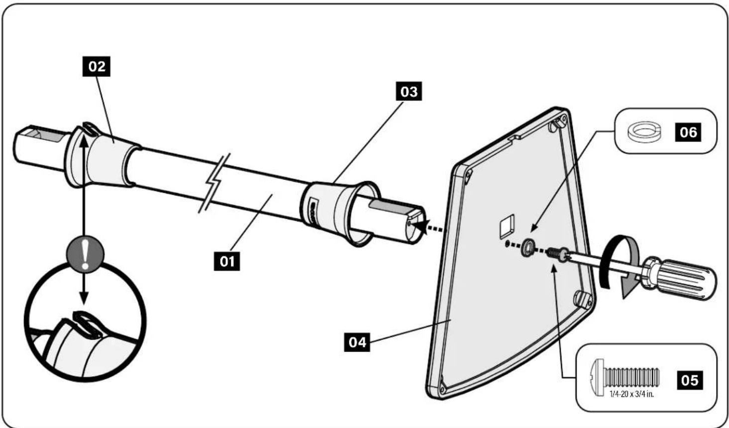
text_image
02 01 03 04 05 06 1/4-20 x 3/4 in. 05STEP 3
Route Speaker Power Cable
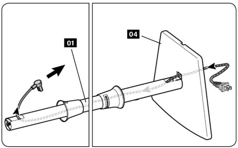
text_image
01 04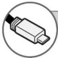
USB [OPTIONAL]
NOTE: USB, if required (see your speaker manual), installs easier AFTER the power cable.
![SANUS WSSE12 - USB [OPTIONAL] - 1](/content/2026/04/672301/images/88100a5eaa618a70476b4c49660847046e31fb8c1c306ccd5175da7205c41d56.jpg)
text_image
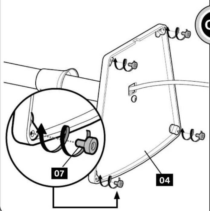
01STEP 4
Install Rubber Pads -or- Carpet Spikes
Rubber Pads
Twist rubber pads 07 into the base 04
text_image
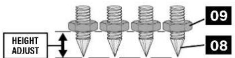
07 04Optional Carpet Spikes
WARNING: The ends of carpet spikes 08 are sharp and may scratch flooring, damage wiring, or be hazardous to children.
text_image
HEIGHT ADJUST 09 08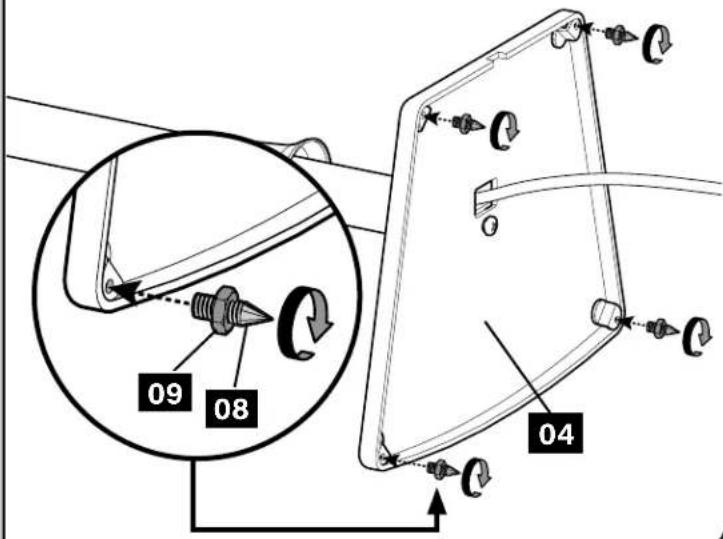
text_image
09 08 04STEP 5
Attach Top Bracket
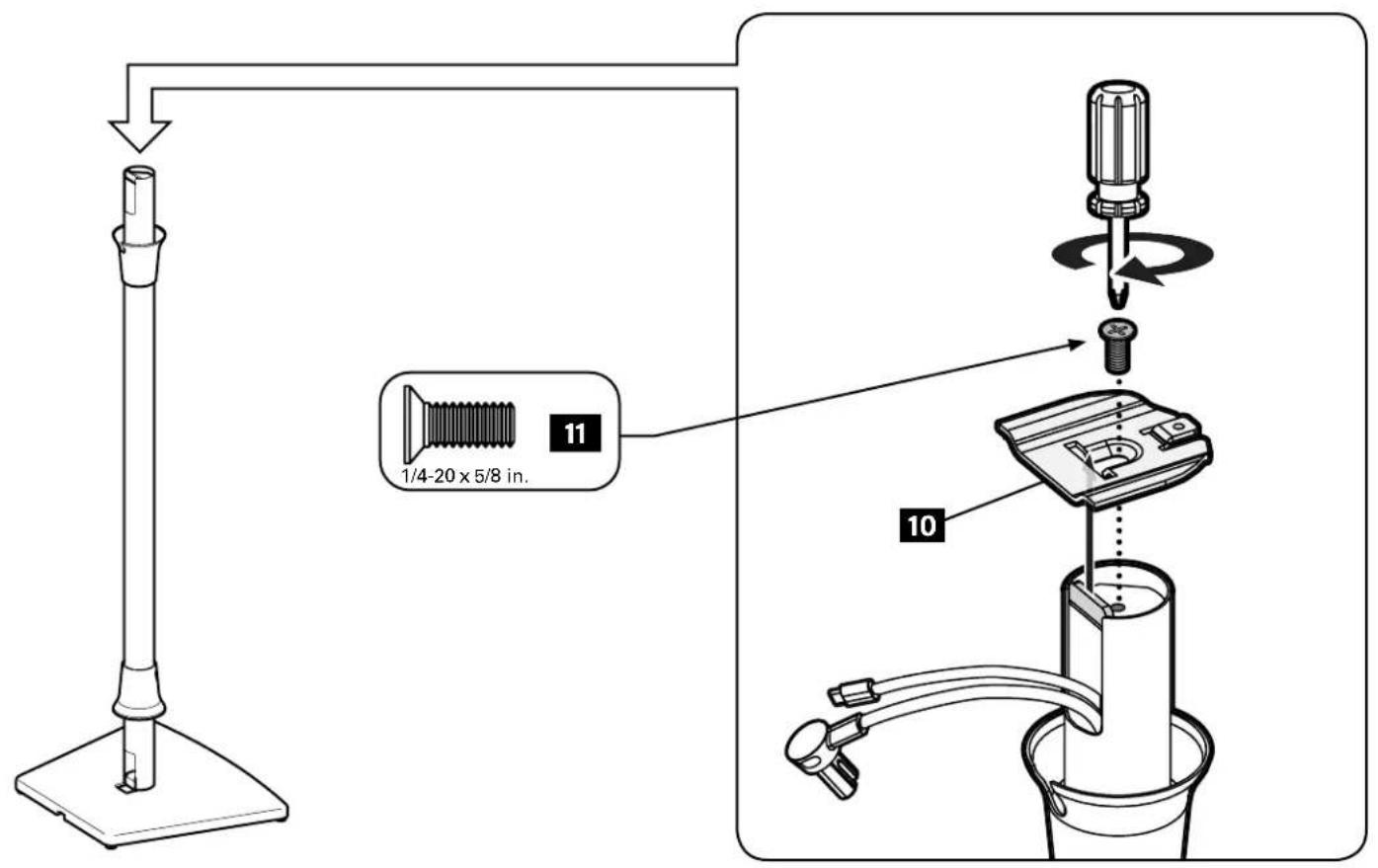
text_image
1/4-20 x 5/8 in. 11 10STEP 6
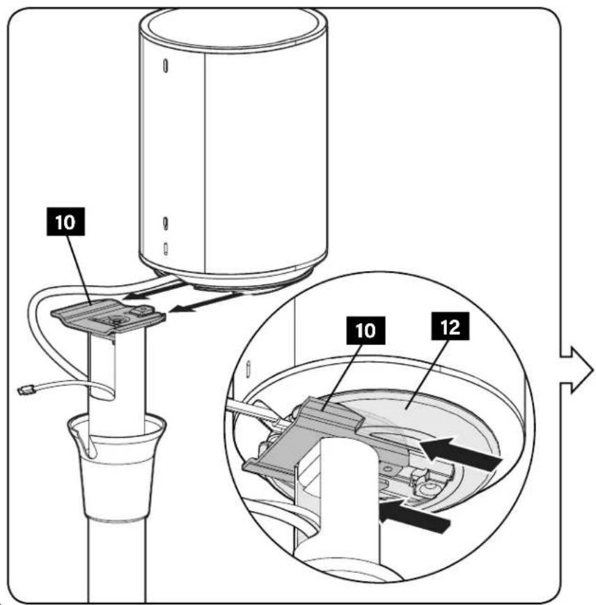
Install Speaker Bracket
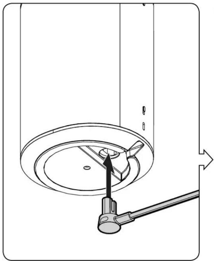
natural_image
Technical diagram of a mechanical assembly with a central rotating component and a lever, showing no text or symbols.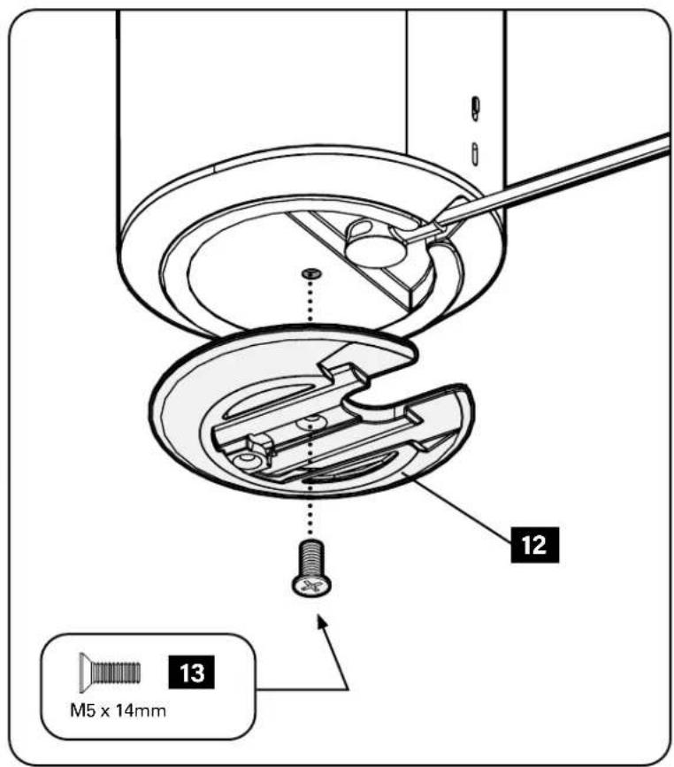
text_image
M5 x 14mm 12 13STEP 7
Attach Speaker
text_image
10 10 12
text_image
10-24 x 3/8 in. 14STEP 8
Adjust Cables
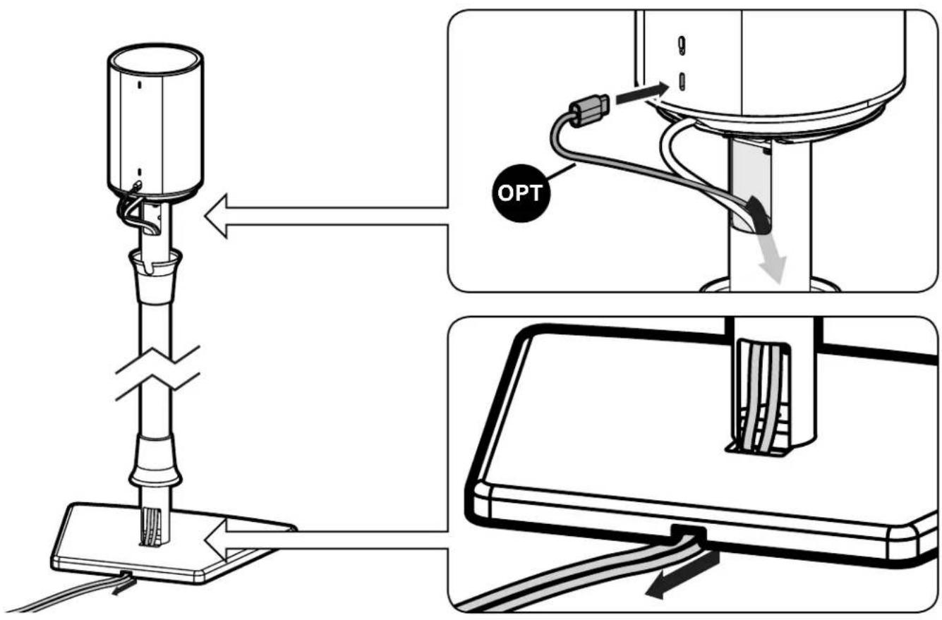
text_image
Technical diagram showing a device with labeled components and directional arrows indicating assembly or operation.STEP 9
Position Collars
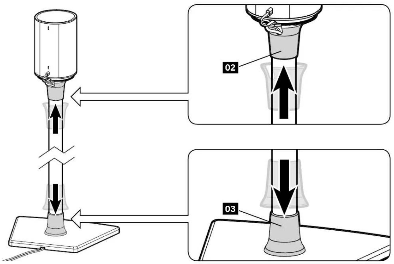
text_image
Diagram illustrating a mechanical or fluidic device operation with labeled parts 02 and 03, showing directional movement and force directions.
text_image
enjoyESPAÑOL
A brand of □ legrand
Thank you for choosing SANUS! Please take a moment to let us know how we did:
Legrand AV Inc.
6436 City West Parkway
Eden Prairie, MN 55344 USA
US: +1 (800) 359-5520
Legrand AV Netherlands B.V.
Franklinstraat 14
6003 DK Weert Netherlands
UK: +44 (0) 800 056 2853
EMEA: +31 (0) 495 580 852
Authorized Representative for the UK
Starline Holding Technology Ltd.
Unit C Island Road
Reading RG2 ORP UK
Legrand AV Inc. and its affiliated corporations and subsidiaries (collectively, "Legrand"), intend to make this manual accurate and complete. However, Legrand AV makes no claim that the information contained herein covers all details, conditions, or variations. Nor does it provide for every possible contingency in connection with the installation or use of this product. The information contained in this document is subject to change without notice or obligation of any kind. Legrand AV makes no representation of warranty, expressed or implied, regarding the information contained herein. Legrand AV assumes no responsibility for accuracy, completeness or sufficiency of the information contained in this document.
©2022 Legrand AV Inc. All rights reserved. SANUS is a brand of Legrand.
All other brand names or marks are used for identification purposes and are trademarks of their respective owners.
Legrand AV Inc. · 6436 City West Parkway · Eden Prairie, MN 55344 USA
6901-603096 00