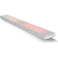
Vision Plus 3200 - Heating Heatscope - Free user manual and instructions
Find the device manual for free Vision Plus 3200 Heatscope in PDF.


User questions about Vision Plus 3200 Heatscope
0 question about this device. Answer the ones you know or ask your own.
Ask a new question about this device
Download the instructions for your Heating in PDF format for free! Find your manual Vision Plus 3200 - Heatscope and take your electronic device back in hand. On this page are published all the documents necessary for the use of your device. Vision Plus 3200 by Heatscope.
USER MANUAL Vision Plus 3200 Heatscope
AND INSTRUCTION MANUAL
Electric ambient carbon radiant heater
for indoor and outdoor areas
MANUEL ORIGINAL D'INSTALLATION
ET D'UTILISATION
Ceiling Installation
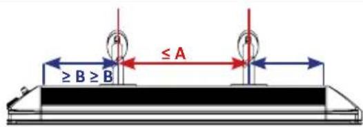
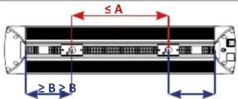
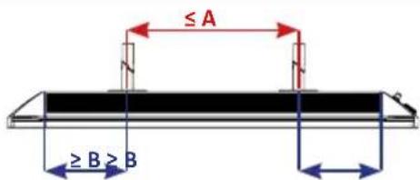
MHS-SM2800/MHS-SP2800≤370 mm≥175 mm
MHS-VT1600/MHS-VE1600
MHS-VT2200/MHS-VE2200
MHS-VT3200/MHS-VE3200
AB
≤300 mm ≥ 175 mm
≤650mm≥175mm
≤ 1150 ~mm ≥ 175 ~mm
DE Wandmontage
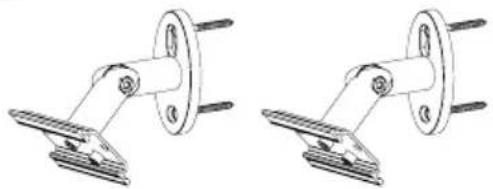
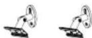
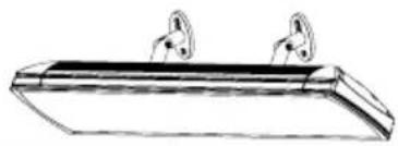
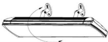
EN Wall mounting
FR Installation au mur
IT Installazione a parete
ES Instalación en pared
NL Muurmontage
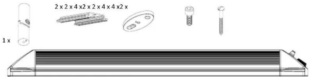
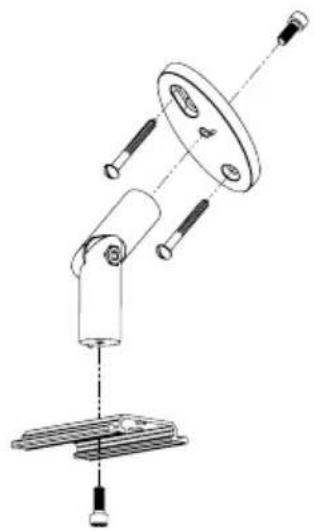
1. 2 ×
2.
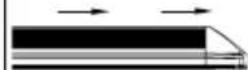
3.
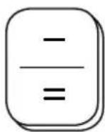
DE Manuelle Steuerung
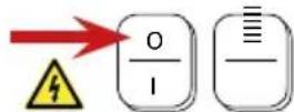
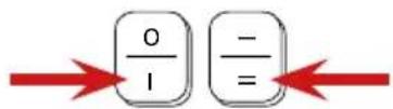
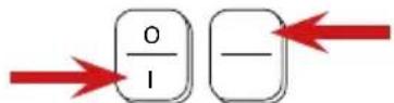
EN Manual control
FR Contrôle manuel
IT Controllo manuale
ES Control manual
NL Handmatige regulering
MHS-SM1600BK.100, MHS-SM2200BK.100, MHS-SM2800BK.100, MHS-SM1600WT.100, MHS-SM2200WT.100, MHS-SM2800WT.100
MHS-VE1600BK.100, MHS-VE2200BK.100, MHS-VE3200BK.100, MHS-VE1600WT.100, MHS-VE2200WT.100, MHS-VE3200WT.100
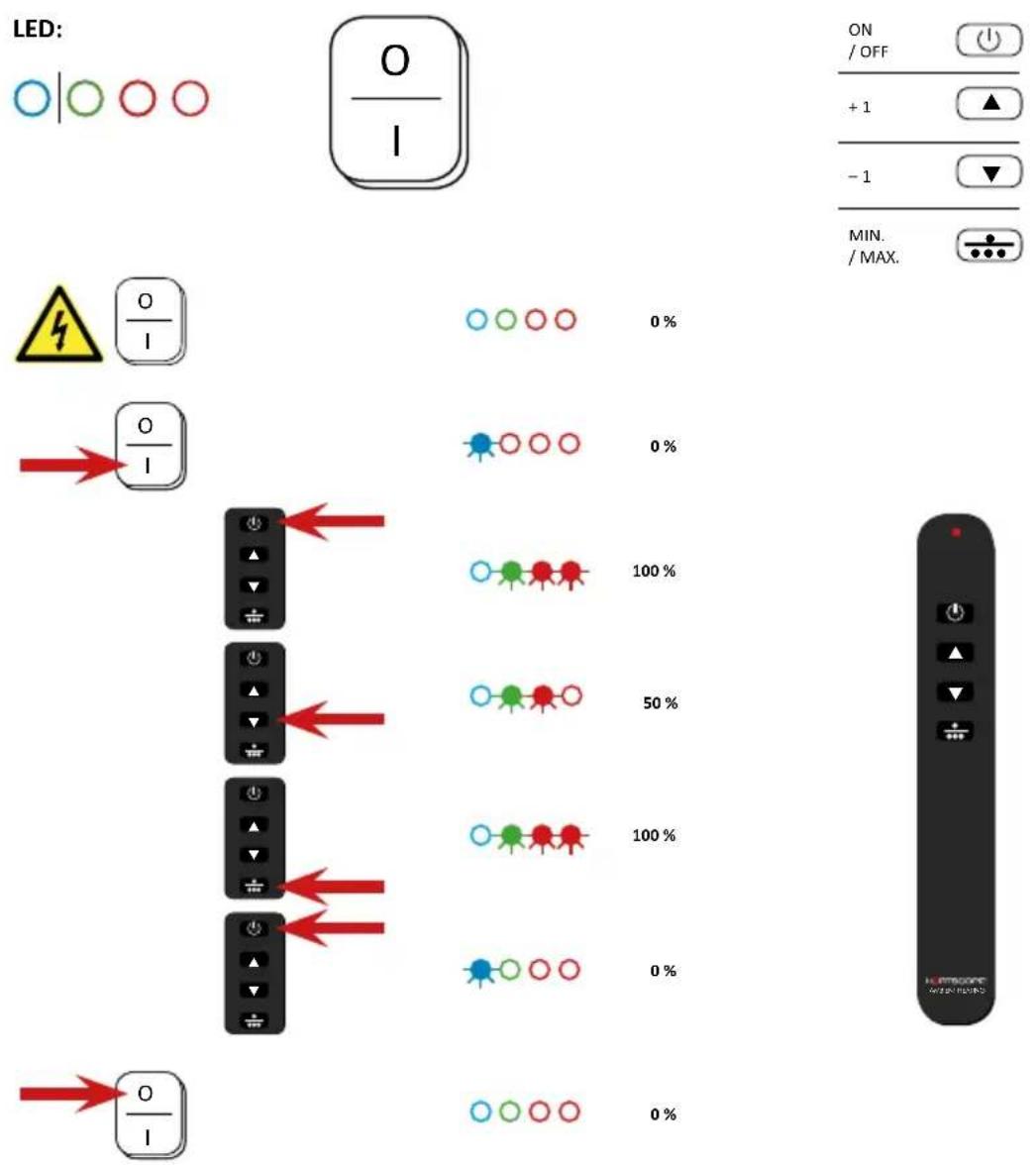
LED:







DE IR-Fernbedienung
EN IR remote control
FR IR télécommande
IT Telecomando ad infrarossi
ES Control remote IR
NL IR afstandsbediening
MHS-SP1600BK.100, MHS-SP2200BK.100, MHS-SP2800BK.100, MHS-SP1600WT.100, MHS-SP2200WT.100, MHS-SP2800WT.100
MHS-VT1600BK.100, MHS-VT2200BK.100, MHS-VT3200BK.100, MHS-VT1600WT.100, MHS-VT2200WT.100, MHS-VT3200WT.100
DE Elektroanschluss
EN Electrical connection
FR Connexion électrique
IT Connessione elettrica
ES Conexión electrica
NL Elektrische aansluiting
MHS-SP1600BK.100, MHS-SP2200BK.100, MHS-SP2800BK.100, MHS-SP1600WT.100, MHS-SP2200WT.100, MHS-SP2800WT.100
MHS-VT1600BK.100, MHS-VT2200BK.100, MHS-VT3200BK.100, MHS-VT1600WT.100, MHS-VT2200WT.100, MHS-VT3200WT.100
HEATSCOPE SP // HEATSCOPE VT
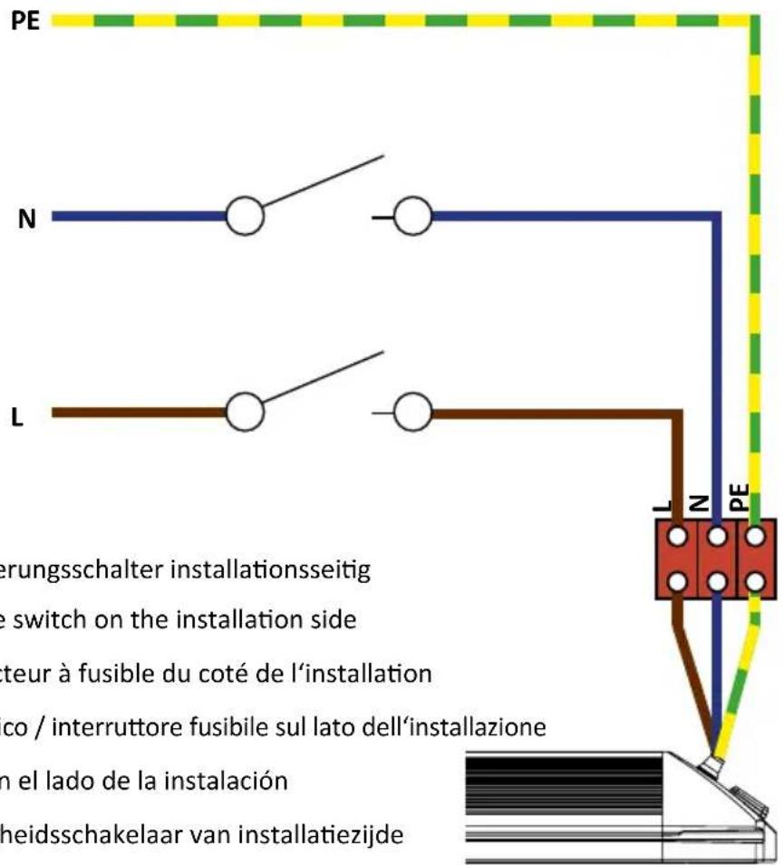
DE Trennschalter / Sicherungsschalter installationsseitig
EN Circuit breaker / fuse switch on the installation side
FR Disjoncteur / Disjoncteur à fusible du (:é de l'installation
IT Interruttore automatico / interruptore fusibile sul lato dell'installazione
ES Disyuntor / fusible en el lado de la instalacion
NL Onderbreker / Veiligheidsschakelaar van installmentiezijde
DEB
The supply cable must be connected generally in a commercially available wet room distribution box with IP65 protection class acc. to IEC or UL/ CSA (not within the scope of supply).
#
MHS-SM1600BK.100, MHS-SM2200BK.100, MHS-SM2800BK.100, MHS-SM1600WT.100, MHS-SM2200WT.100, MHS-SM2800WT.100
MHS-VE1600BK.100, MHS-VE2200BK.100, MHS-VE3200BK.100, MHS-VE1600WT.100, MHS-VE2200WT.100, MHS-VE3200WT.100

HEATSCOPE® SM // HEATSCOPE® VE
DE Trennschalter / Sicherungsschalter installationsseitig
EN Circuit breaker / fuse switch on the installation side
FR Disjoncteur / Disjoncteur à fusible du (:oté de l'installation
IT Interruttore automatico / interruptore fusibile sul lato dell'installazione
ES Disyuntor / fusible en el lado de la instalacion
NL Onderbreker / Veiligheidsschakelaar van installmentiezijde
ITE
EN HEATSCOPE VISION and SPOT - Wiring / Connecting regulation
Pillar terminal 1000K / 3 + 4 MDS HT 0,5 - 6mm^2 3 + 4 pol.: (1) Wire protection with pin-in-hole protection for stripped litz wires and litz wires with cable end sleeves, (2) Tighten screws with 0.5Nm , (3) Wiring / Connection Version 2, shortened litz wire 1 - 2.5mm^2 , stripped 6 - 7mm , (4) Wiring / Connection Version 1, standard litz wire 1 - 2.5mm^2 , with cable end sleeve
FR HEATSCOPE\* VISION et SPOT - Regles de cablage / raccordement
EN Inadmissible, defective, and dangerous wirings / connections
(1) terminal is tightened too strong, (2) isolation errors and missing air and creepage distances, (3) different wirings are seized in one terminal, (4) too many conductors in one terminal, (5) terminal tightened over isolation, (6) dangerous twirling of litz wires by hand, (7) no pressing signs of a safe terminal connection at wiring, (8) twirling of litz wires by hand with isolation tape
FR Cablages / Raccordements inadmissibles, defectieux et dangereux
MHS-SM1600BK.100, MHS-SM2200BK.100, MHS-SM2800BK.100
MHS-SM1600WT.100, MHS-SM2200WT.100, MHS-SM2800WT.100
MHS-SP1600BK.100, MHS-SP2200BK.100, MHS-SP2800BK.100
MHS-SP1600WT.100, MHS-SP2200WT.100, MHS-SP2800WT.100
HEATSCOPE® VISION - Manuelle Regelung, 4-polige Zuleitung
HEATSCOPE® infrared heaters must be installed and executed only by an authorized expert / professional electrician.
All relevant local building and fire safety regulations must be observed.
WARNING: This unit is not equipped with an application to regulate the room temperature. The heater must not be used in small rooms inhabited by people who cannot leave the room unaided, unless constant supervision is ensured.
Be careful when operating the unit. Children younger than 3 years must be kept away, unless they are overseen all the time. Children older than 3 years and younger than 8 years are allowed to switch on and off the unit, if they are overseen, or if they were instructed how to use the unit safely and have received instructions how to operate/use the unit, assumed the unit is installed properly.
CAUTION: Some parts of the unit get very hot and may cause burns! High cautiousness is imperative, if children or persons with reduced physical, sensory or mental abilities or lack of experience and/or knowledge. are present in the room.
Children older than 3 years and younger than 8 years are not allowed to connect the plug, to control the unit, to clean the unit and/or to maintain the unit.
Children older than 8 years and persons with reduced physical, sensory or mental abilities or lack of experience and/or knowledge can use this unit, if they are overseen, or if they were instructed how to use the unit safely and have received instructions how to operate/use the unit and which endangerments may result during the use of the unit. Children must not be playing with the unit. Cleaning and maintenance must not be done by children, unless they are supervised by a person responsible for their safety.
The unit must never be used unattended. Children must be supervised at all times to ensure that they do not play with the unit, switch it on unintentionally or adjust it.
- Please check that your HEATSCOPE® radiant heater and accessories are complete and not damaged. In special take care of the glass holders of the model range VISION, which hold and surround the glass ceramic front screen. Press the holders carefully back in position, until they click into place again.
If the housing or reflector is deformed/damaged or the heating element is broken, do not use the HEATSCOPE® unit. Please contact the vendor or the manufacturer.
The cable must not be crushed, squeezed or damaged.
If the unit or accessories show signs of defects, cracking, breakage or other damage or if the industrial glass ceramics screen is damaged, discontinue use and have them repaired. In this case, disconnect the unit from the power supply, return it to the manufacturer or dispose of it. The unit should be labelled accordingly to prevent it being reconnected.
- For installation use only the supplied accessories or original accessories approved by the manufacturer. The power cable or other components of the HEATSCOPE® radiant heater may only be replaced by a professional servicing company enlisted by the manufacturer.
The supply cable must be connected generally in a commercially available wet room distribution box with IP65 protection class acc. to IEC or UL / CSA (not within the scope of supply). - The HEATSCOPE® is protected against splashing water and has an IP44 protection class rating (model VISION) resp. IP24 (model SPOT). Nevertheless, it is mandatory to install the unit on a surface where it is well protected from any weather influences like rain and dust from above; so the HEATSCOPE® has to be installed under a roof, an overhang or in combination with the optional available weather shield.
- As soon as the unit is connected to a power source and switched on using an „ON/OFF" switch or other operating component, it takes a maximum of 15-30 seconds until it reaches its operating temperature.
- CAUTION: Risk of burns! The front screen (approx. 300^ ) and protective fin front (approx. 300^ ) gets very hot when the unit is operating.
Do not cover either part of the front or the entire front of the radiant heater. Do not touch any part of the HEATSCOPE® during operation and up to 30 minutes after switching it off. - For your own safety, never dry textiles or other materials using the HEATSCOPE®. Covering the radiant heater may result in a fire! Always maintain a distance from the heating surface of the HEATSCOPE® of at least 150 cm from textiles, cloth and other easy inflammable soft materials.
- Ensure that cables, furniture, flammable materials or other objects do not come into contact with the surface of the radiant heater and never cover the unit. Under no circumstances should the unit be covered or enclosed with insulating or similar materials. Adequate ventilation surrounding the heater must be ensured at any time. Ledgers, beams and rafters must not be cut into or grooved to install the infrared
heater.
When installing the HEATSCOPE® radiant heater, ensure that the lower edge of the unit is at least 180 cm from the ground and the safety clearances from the wall and ceiling set out in this manual are maintained. Always maintain a distance from the heating surface of the HEATSCOPE® of at least 150 cm from textiles, cloth and other easy inflammable soft materials.
- Disconnect the radiant heater from the power supply before cleaning it, adjusting the angle or removing it from the wall/ceiling. Wait until the heating elements are not glowing any more and the housing is noticeably cooled down. If buried cables are used, switch off the power using an omnipolar switch.
- The HEATSCOPE® features an omnipolar „ON/OFF“ switch. The unit can be controlled manually either using an IR remote control (supplied, depending on the model) or a selector switch on the unit itself (depending on the model as well). The unit must be connected to a residual current circuit breaker and a fuse on the installation side.
- The unit must only be used with an approved isolating system, which must be built in the existing electrical installation acc. to the facility regulations. The heater comes as standard with a separate open-ended cable for connection purposes.
- The power cable or buried cable with omnipolar switch may only be replaced by a professional specialist electrical company enlisted or approved by the manufacturer. Heating elements, other components or parts of the housing may only be replaced by a service organisation enlisted by the manufacturer.
If you yourself or someone enlisted by you carries out repairs, they will not be covered by the guarantee. Improper repairs and incorrect installation or operation shall invalidate the guarantee immediately.
- If the heater was installed inappropriately or was connected unhomogeneously with the local electrical supply cable, high transfer resistances may occur, which lead to overheating of the device. For the heating system and many custom applications the heaters were equipped with a NTC temperature control and an additional latching temperature limiter.
Ordinarily possible over heating due to inappropriate installation is protected by the NTC temperature control and the latching temperature limiter. If overheating of a carbon heating element occurs due to interlinkage of mounting and installation mistakes, the carbon filaments inside of the quartz tubes will fuse and safely disconnect the current flow. Even after a mechanical break of the quartz tubes, the carbon heating spirals will not work any longer. Besides the fin front screen of the SPOT heaters
and the glass ceramic, high temperature resistant front screen of the VISION heaters provide best protection of the installed carbon heating elements.
Functional description of the NTC temperature control: If the system temperature of the electronic control exceeds 103^ , the upper heating element will shut off temporary by default to avoid over heating of the electronic parts. After a short time the heating element will switch on automatically again. The self-controlled shut off of the heater will take place only, if the heat dissipation inside the device is inappropriate, if the heat radiation is interfered or if the ambience temperaure is way too high. Apart from that the NTC temperature control supports energy safings, if the ambient temperatures are too high and the highest heating level of the heating unit is not necessary.
Functional description of the latching temperature limiter: If the NTC temperature control is not working against expectations, the latching temperature limiter will shut down the lower heating element permanently, until the heater is shut off totally by hand. After cooling down (warm to the touch) and fixing the inappropriate heat dissipation inside the device and/or the interfered heat radiation the heater can be switched on again. If the lower heating element shuts down once more, a system malfunction or a heat dissipation inside the device or an interference of the heat radiation or an error in the electrical installation may be the reason. If a system malfunction inside the device causes the shut down, the heater must be repaired by a professional technician; please contact your dealer immediately. If a wrong cable connection causes the shut down, this has to be checked and fixed through a professional electrician on the spot.
Installation and connecting regulations with tested and approved luster terminals are part of the delivered equipment.
- The radiant heater must not be installed directly below a power source/socket. The sides of the unit must be at least 20~cm from the nearest power source. Sockets/ power sources must be freely accessible at all times and comply with the following specifications: 220-240 V AC , 50/60 Hz, 16 A with 16 A fuse. No other loads may be connected to this power source.
- The radiant heater must not be installed in rooms where there is high humidity (bathroom, spa, pool etc.) in close vicinity to bathtubes, showers or pools. The distance to the bathtub or shower must be at least 100cm and the distance to the pool at least 200cm . A person standing in the bathtub, shower or pool should never reach the switch or controller of the heater. If the HEATSCOPE® is installed in such an environment with high humidity, the switches or other operating components
must be positioned in such a way that they cannot be touched by persons who are in direct contact with water. Bathroom heaters must not be operated with a separate automatic thermostat or timer. When a radiant heater is installed in a bathroom, the CE standard requires that at least one heating element visibly „glows“ as soon as the unit is switched on.
- Disconnect the radiant heater from the power supply before cleaning it, adjusting the angle or removing it from the wall/ceiling. Wait until the heating elements are not glowing any more and the housing is noticeably cooled down. If buried cables are used, switch off the power using an omnipolar switch. Wait at least 30 minutes after the last use before you start cleaning it. All surfaces should be cleaned using a damp cloth only. Never use cleaning products containing alkaline substances such as sodium hydroxide or soap, surfactants or solvents such as alcohol. Use only a very soft cloth or a brush for the reflector and the heating elements.
- Always remember to switch off the unit after use.
INSTALLATION REGULATIONS FOR MHS HEATSCOPE VISION AND SPOT INFRARED HEATERS
Professional and safe Installation of HEATSCOPE® VISION and SPOT heaters acc. to int. standards:
Standards: All MHS HEATSCOPE * VISION and SPOT infrared design heaters are designed, developed and manufactured acc. to EN / IEC 60335-1 and EN / IEC 60335-2-30 (Household and similar electrical appliances Safety)
Installation: Installation of heaters must be done acc. to installation guideline of the ORIGINAL HEATSCOPE* INSTALLATION AND INSTRUCTION MANUAL. Min. distance between the two mounting brackets on back of the heater as designated, min. installation height: 1.8 m from ground, min. distances to walls, ceilings or other materials as designated in the manual. Installation on a ceiling should reach a min. distance of 2.2 m from ground to avoid any contact with hair, head, or skin. Despite IP X4 protection the heater should be installed well covered against rain and direct water impacts to guard the high end reflector shields and protect their full functionality.
ATTENTION! Inadequate derivation of heat will cut off the lower heating element shortly after activation. After some time of cooling down this heating element will power up again. Inappropriate installation and inadequate derivation may overload the heater. For safety reasons a temperature limiter is installed, which cuts off the upper heating element permanently due to inappropriate installation or incorrect electrical connection – until electrical connection is disconnected and the heating element is totally cooled down. In case the heater is damaged by improper installation or by a missing heat derivation, the manufacturer's guarantee will no longer be applicable.
Professional and safe electrical connection of HEATSCOPE® VISION and SPOT heaters acc. to int. standards:
Standards:

The electrical installation must be done by a professional electrician acc. to DIN VDE 0298-4 / IEC 60364-5-52, current load of electrical wirings / connections acc. to DIN VDE 0113-1 / EN 60204-1 for long-term usage with environmental temperatures of 40^ , with conversion factor for higher environmental and wiring / connection temperatures, accumulation of wirings or connections for the same type of installment and max. wiring / connection lengths acc. to DIN VDE 0100-520 Blt. 2 / EN 60204-1. Due to the listed impacts on wiring / connection longer wirings / connections from distribution board to cable of heater should be constructed one cross section higher (cf. table below). Connection of supply cable and heater cable should only be done with tested pillar terminals with wire protection and central fence.
Example: ADELS 1000K 3 or 4 MDS HT 0,5 - 6 mm², 40 Amp. Testing Signs: VDE, UL, CSA, KEMA, SEMKO, FI (cf. table)
ATTENTION! MHS HEATSCOPE*heaters are working in high power levels of 1600 W up to 3200 W (= 7 A up to 14 A). Inappropriate wiring / connection cross sections and inadequate connections of supply and heater cables may cause contact resistances, which will boost significantly during operation. In general inadmissible high temperatures will occur at contacts of switches, on the electrical board, and at contacts of the heating elements, which may cause damage of switches, melting of contacts, damage of heating elements and melting of isolation of wiring. In case the heater is damaged by improper installation or by a missing heat derivation, the manufacturer's guarantee will no longer be applicable.
Table 1: Cross section of wiring / connection and fuse from supply to heater considering longer wiring /connections and environmental temperatures
| per 1 piece HEATSCOPE® heater heater cable | cable connecting terminal | initial 3 / 4 core | 1 wiring connection from heater cable to supply | fuse |
| VT1600 + SP1600: 220-240 VAC, 7,0 A: 3 x 1,5 | mm² 1000 K / 3 MDS | HT 0,5-6,0 mm² | DIN VDE 0100-520 Blt. 2 / EN 60204-1 | DIN VDE 0100-520 Blt. 2 / EN 60204-1 |
| VE1600 + SM1600: 220-240 VAC, 7,0 A: 4 x 1,5 | mm² 1000 K / 4 MDS | HT 0,5-6,0 mm² | ||
| VT2200 + SP2200: 220-240 VAC, 9,6 A: 3 x 1,5 | mm² 1000 K / 3 MDS | HT 0,5-6,0 mm² | ||
| VE2200 + SM2200: 220-240 VAC, 9,6 A: 4 x 1,5 | mm² 1000 K / 4 MDS | HT 0,5-6,0 mm² | ||
| SP2800: 220-240 VAC, 12,2 A: 3 x 1,5 mm² | 1000 K / 3 MDS HT | 0,5-6,0 mm² | ||
| SM2800: 220-240 VAC, 12,2 A: 4 x 1,5 mm² | 1000 K / 4 MDS HT | 0,5-6,0 mm² | ||
| VT3200: 220-240 VAC, 13,9 A: 3 x 1,5 mm² | 1000 K / 3 MDS HT | 0,5-6,0 mm² | ||
| VE3200: 220-240 VAC, 13,9 A: 4 x 1,5 mm² | 1000 K / 4 MDS HT | 0,5-6,0 mm² | ||
| per 2 pieces HEATSCOPE® heater heater cable | cable connecting terminal | initial 3 / 4 core | 1 wiring connection from heater cable to supply | fuse |
| VT1600 + SP1600: 220-240 VAC, 7,0 A: 3 x 1,5 | mm² 1000 K / 3 MDS | HT 0,5-6,0 mm² | DIDVDE 0100-520 Blt. 2 / EN 60204-1 | DIN VDE 0100-520 Blt. 2 / EN 60204-1 |
| VE1600 + SM1600: 220-240 VAC, 7,0 A: 4 x 1,5 | mm² 900 K / 4 MDS | HT 0,5-6,0 mm² |
Dear Customer,
thank you for choosing a HEATSCOPE® electric radiant heater. This top-quality infrared ambient heater is manufactured in Germany and complies with CE/EN/DIN standards and EU directives. Only tested, environmentally friendly materials and components are used.
HEATSCOPE® infrared heaters are producing high energy efficient heat based on IR fast midwave up to efficient IR long wave technology.
Eye, skin and organism harming IR short waves are not produced by HEATSCOPE® carbon heating elements in any way.
Designed for private and commercial use for wall and ceiling mounting in well covered, sheltered indoor and outdoor areas, HEATSCOPE® carbon radiant heaters produce heat within seconds wherever it is needed. The infrared radiant heater allows you to transport heat over a distance of up to 3 metres, ideally in a specific direction.
Before installing the unit, please read this instruction manual carefully. Follow the information given to avoid endangering yourself, your family, your friends and your acquaintances. If you have any questions, contact the vendor or manufacturer.
Please keep this instruction manual in a safe place. Pass on the manual to any subsequent owner of the HEATSCOPE® unit and ensure that any supplements received are included along with it (cf. www. heatscope.com).
Prior to installation, ensure that the operating voltage matches the one specified on the name plate of the HEATSCOPE® unit!
This instruction manual is intended solely for the standard products available. The technical data, installation requirements and dimensions of custom made, special versions may differ.
This manual is also available online:
www.munich-home-systems.com - end of front page
(www.munich-home-systems.com/wp-content/uploads/HEATSCOPE_CB-Manual_V+S.pdf)
Models
HEATSCOPE SPOT - manual control, 4 core cable
SPECIFICATIONS: ON/OFF + 2 manually switchable power levels (100% or 50%)
MHS-SM1600BK.100, MHS-SM2200BK.100, MHS-SM2800BK.100
MHS-SM1600WT.100, MHS-SM2200WT.100, MHS-SM2800WT.100
HEATSCOPE® SPOT - 2 power levels, remote controllable, 3 core cable
SPECIFICATIONS: ON/OFF + 2 remote controllable power levels (100% or 50%), IR remote control
MHS-SP1600BK.100, MHS-SP2200BK.100, MHS-SP2800BK.100
MHS-SP1600WT.100, MHS-SP2200WT.100, MHS-SP2800WT.100
HEATSCOPE® VISION - manual control, 4 core cable
SPECIFICATIONS: ON/OFF + 2 manually switchable power levels (100% or 50%, external)
MHS-VE1600BK.100, MHS-VE2200BK.100, MHS-VE3200BK.100
MHS-VE1600WT.100, MHS-VE2200WT.100, MHS-VE3200WT.100
HEATSCOPE® VISION - remote controllable, 3 core cable
SPECIFICATIONS: ON/OFF + 2 remote controllable power levels (100% or 50%), IR remote control
MHS-VT1600BK.100, MHS-VT2200BK.100, MHS-VT3200BK.100
MHS-VT1600WT.100, MHS-VT2200WT.100, MHS-VT3200WT.100
Dimensions & Specifications
| Art.-No. Colour Power Weight | Sizes (incl. brackets) | |||
| MHS-SM1600BK.100 / MHS-SP1600BK.100 | Front: black Corpus: 2200W 4.5 kg | 1600 W 4.0 kg 670 x 82 mm | 184 x 82 mm | |
| MHS-SM2200BK.100 / MHS-SP2200BK.100 | 810 x 184 x 82 mm | |||
| MHS-SM2800BK.100 / MHS-SP2800BK.100 | Corpus: 2800W 4.5 kg | 890 x 184 x 82 mm | ||
| MHS-SM1600WT.100 / MHS-SP1600WT.100 | Front: white Corpus: 2200W 4.5 kg | 1600 W 4.0 kg 670 x 82 mm | 184 x 82 mm | |
| MHS-SM2200WT.100 / MHS-SP2200WT.100 | kg 810 x 184 x 82 mm | |||
| MHS-SM2800WT.100 / MHS-SP2800WT.100 | Corpus: 2800W 4.5 kg | kg 890 x 184 x 82 mm | ||
| MHS-VT1600BK.100 / MHS-VE1600BK.100 | Front: black Corpus: titan | 1600 W 6.0 kg 810 x 184 x 90 mm | 184 x 90 mm | |
| MHS-VT2200BK.100 / MHS-VE2200BK.100 | 2200 W 8.0 kg 1160 x 184 x 90 mm | x 184 x 90 mm | ||
| MHS-VT3200BK.100 / MHS-VE3200BK.100 | 3200 W 1.0 kg 1660 x 184 x 90 mm | x 184 x 90 mm | ||
| MHS-VT1600WT.100 / MHS-VE1600WT.100 | Front: white Corpus: white | 1600 W 6.0 kg 810 x 184 x 90 mm | 184 x 90 mm | |
| MHS-VT2200WT.100 / MHS-VE2200WT.100 | 2200 W 8.0 kg 1160 x 184 x 90 mm | x 184 x 90 mm | ||
| MHS-VT3200WT.100 / MHS-VE3200WT.100 | 3200 W 1.0 kg 1660 x 184 x 90 mm | x 184 x 90 mm | ||
Unpacking the unit / packaging
Unpack the unit and the accessories carefully. When opening the packaging, do not use sharp objects that could damage the unit.
This product comes supplied in environmentally friendly packaging. All HEATSCOPE® packaging that comes into circulation either directly or via the trade is certified in accordance with §6 of the German Packaging Directive. As a result, all HEATSCOPE® packaging can be disposed of in an environmentally friendly manner in collection containers for packaging materials. The relevant legal regulations must be observed here. Further information is available from the manufacturer.
Care information! Important! Clean the unit with a damp cloth before using it for the first time. Do not use cleaning products containing alkaline substances such as sodium hydroxide or soap, surfactants or solvents/alcohol.
Installation instructions
The INDIVIDUAL options for installing the HEATSCOPE® radiant heater are shown in the diagrams in the beginning of this manual.
Ensure that the radiant heater is fixed securely to the installation surface. In terms of tensile and shear strength, the fixings must be able to withstand at least 3 times the weight of the radiant heater (including accessories) that is to be installed. When installing the unit, use the correct screws (supplied) for the surface.
Please bear in mind that you always need two fixing brackets to fix your unit safely. Please refer to the minimum installation dimensions for the unit (cf. „minimum distances“).
It is mandatory to install the unit on a surface where it is well protected from any weather influences like rain and dust from above; so the HEATSCOPE® has to be installed under a roof, an overhang or in combination with the optional available weather shield.
Operation, installation instructions and minimum distances
Once you have installed the unit, you can use it for the first time.
The HEATSCOPE® features an omnipolar „ON/OFF“ switch. You can control the radiant heater manually using a selector switch on the unit itself or using an IR remote control which comes supplied (depending on the model). The unit must be connected to a residual current circuit breaker and a fuse!
Install the unit only in indoor or outdoor areas that are well protected from any weather influences from above like rain and dust. The heater is protected from lateral spray water, but it has to be covered with a roof or a similar canopy like the optional available weather shield upwards.
CAUTION: The mounting of the heater on the wall and on the cieling as well as in glass houses and conservatories has professionally to be accomplished solely according to the mounting regulations. Specified safety distances given are min. values and may deviate from the local building and fire safety regulations. The safety distances as well as the local building and fire safety regulations must be
complied with at all times, leave improper stated installation settings undone at any time. Deviant installation settings require the technical approval of the manufacturer, who can prescribe the installation of temperature and weather protection shields. In the case of a deviant installation setting without approval of the manufacturer danger for people and environment occurs. Warranty and guarantee expires for all heaters, which are not installed according to this operation and installation manual!
Other protective measures may need to be taken in accordance with local fire safety regulations, e.g. for installation on combustible surfaces.
All cables must be positioned so that they cannot come into contact with the radiant heater at any time. The radiant heater must not be installed directly below a power socket. The sides of the HEATSCOPE® must be at least 20cm from any power sockets.
Care, maintenance and service
Before cleaning and maintaining your HEATSCOPE®, disconnect it from the power supply or, if buried cables are used, switch it off via the omnipolar switch. Ensure that the unit has cooled down – wait at least 30 minutes after the last use before you start cleaning it.
All surfaces should be cleaned using a damp cloth only. Never use cleaning products containing alkaline substances such as sodium hydroxide or soap, surfactants or solvents such as alcohol.
Use only a very soft cloth or a brush for the reflector and the heating elements.
Removal from service / disposal
When the unit reaches the end of its life, it must be removed from service by a specialist in accordance with the relevant regulations and steps must be taken to ensure that it cannot be put into use again.
The unit must be disposed of professionally and in an environmentally friendly manner. The relevant legal regulations must be observed.
Guarantee and warranty
The HEATSCOPE® is guaranteed for 24 months. The warranty period begins on the date on which the new unit was purchased. Expendable parts or defects that affect the usability of the unit only slightly are not covered by the guarantee. When making a guarantee claim, you must provide the original invoice showing the date of purchase and the unit model.
Processing of guarantee claims
Please contact your dealer/distributor before returning the defective unit along with valid proof of purchase and a detailed description of the fault. Please note: Don't send in any devices to the manufacturer without any former contact with your distributor or dealer. He will inform you about all following steps. The manufacturer will only accept the unit, if it is returned with adequate transport packaging which protects it securely during transport.
The manufacturer will, at its own discretion, fulfil its warranty obligations by either repairing or exchanging the faulty unit or individual parts of the faulty unit. If a unit is replaced, the shape and colour of the new unit may vary slightly from the original one. The original date of purchase shall determine when the guarantee period begins. The guarantee period shall not be extended if the unit was replaced or repaired by the manufacturer.
Warranty exclusions
Damage or defects caused by improper handling or operation as well as defects caused by using nonoriginal parts or the use of accessories not recommended by the manufacturer are not covered by the warranty.
The warranty does not cover damage caused by external influences such as fire, lightning or any transport damages. Liability for consequential damages to persons or property is excluded.
If the serial number of the unit has been changed, removed or defaced, the warranty will be invalid.
All warranty claims shall be forfeited if the unit is opened, altered, modified, rebuilt or repaired by a person not authorized by the manufacturer.
The declaration of conformity (CE, WEEE, RoHS) is available upon request from the manufacturer.
Technical data
| HEATSCOPE® SPOT HEATSCOPE® VISION | ||
| Operating voltage | 220-240 V AC ~, 50/60 Hz 220-240V AC ~, 50/60 Hz | |
| Power at 230 V AC~ | 1600 W / 2200 W / 2800 W 1600 W / 2200 W / 3200 W | |
| Current | 6.96 A / 9.57 A / 12.17 A 6.96 A / 9.57 A / 13.91 A | |
| Power Cord | 1.1 m / 3 x 1.5 mm²1.1 m / 4 x 1.5 mm² | 1.1 m / 3 x 1.5 mm²1.1 m / 4 x 1.5 mm² |
| Max. surface temperature / front | ≤ 400 °C ≤ 300 °C | |
| Max. housing temperature | ≤ 150 °C ≤ 130 °C | |
| Filament temperature | 1100-1300 °C 1100-1300 °C | |
| Heating impact in | 5 sec. 10 sec. | |
| Max. visible light | ≤ 600 Lux ≤ 300 Lux | |
| Installation height | min. 1.8 m / max. 3 m min | 1.8 m / max. 2.5 m |
| IP protection class | IP 24 (with optional available weather shield) | IP 44 (with optional available weather shield) |
| Manual control | ON/OFF + 100%, 50% ON/OFF + 100%, 50% | |
| Remote control | ON/OFF + 100%, 50% ON/OFF + 100%, 50% | |






CONSIGNES DE SECURITE
MHS-SM1600BK.100, MHS-SM2200BK.100, MHS-SM2800BK.100
MHS-SM1600WT.100, MHS-SM2200WT.100, MHS-SM2800WT.100
MHS-SP1600BK.100, MHS-SP2200BK.100, MHS-SP2800BK.100
MHS-SP1600WT.100, MHS-SP2200WT.100, MHS-SP2800WT.100
MHS-SM1600BK.100, MHS-SM2200BK.100, MHS-SM2800BK.100
MHS-SM1600WT.100, MHS-SM2200WT.100, MHS-SM2800WT.100
MHS-SP1600BK.100, MHS-SP2200BK.100, MHS-SP2800BK.100
MHS-SP1600WT.100, MHS-SP2200WT.100, MHS-SP2800WT.100
HEATSCOPE® VISION - controlo manuale, cavo 4 poli
MHS-SM1600BK.100, MHS-SM2200BK.100, MHS-SM2800BK.100
MHS-SM1600WT.100, MHS-SM2200WT.100, MHS-SM2800WT.100
HEATSCOPE® SPOT - 2 power levels, remote controllable, 3 core cable
SPECIFICATIONS: ON/OFF + 2 remote controllable power levels (100% or 50%), IR remote control
MHS-SP1600BK.100, MHS-SP2200BK.100, MHS-SP2800BK.100
MHS-SP1600WT.100, MHS-SP2200WT.100, MHS-SP2800WT.100
HEATSCOPE® VISION - manual control, 4 core cable
SPECIFICATIONS: ON/OFF + 2 manually switchable power levels (100% or 50%, external)
MHS-VE1600BK.100, MHS-VE2200BK.100, MHS-VE3200BK.100
MHS-VE1600WT.100, MHS-VE2200WT.100, MHS-VE3200WT.100
HEATSCOPE® VISION - remote controllable, 3 core cable
SPECIFICATIONS: ON/OFF + 2 remote controllable power levels (100% or 50%), IR remote control
MHS-VT1600BK.100, MHS-VT2200BK.100, MHS-VT3200BK.100
MHS-VT1600WT.100, MHS-VT2200WT.100, MHS-VT3200WT.100
Dimensiones y specifications
| Numero de Articulo Color Poder | Peso | Tamaño(incl. fijaciones) | ||
| MHS-SM1600BK.100 / MHS-SP1600BK.100 | Frente: Negro Corpus:2200W 4.5kg | 1600 W 4.0kg | 670 x 82 mm | 184 x 82 mm |
| MHS-SM2200BK.100 / MHS-SP2200BK.100 | 810 x 184x 82 mm | |||
| MHS-SM2800BK.100 / MHS-SP2800BK.100 | 2800Twa5.0kg | 890 x 184x 82 mm | ||
| MHS-SM1600WT.100 / MHS-SP1600WT.100 | Frente: Blanco Corpus:2200W 4.5kg | 1600 W 4.0kg | 670 x 82 mm | 184 x 82 mm |
| MHS-SM2200WT.100 / MHS-SP2200WT.100 | 810 x 184x 82 mm | |||
| MHS-SM2800WT.100 / MHS-SP2800WT.100 | 2800Twa5.0kg | 890 x 184x 82 mm | ||
| MHS-VT1600BK.100 / MHS-VE1600BK.100 | Frente: Negro Corpus:Titan | 1600 W 4.0kg | 810 x 184 x 90 mm | 184 x 90 mm |
| MHS-VT2200BK.100 / MHS-VE2200BK.100 | 2200 W 4.0kg | 1160x 184 x 90 mm | x 184 x 90 mm | |
| MHS-VT3200BK.100 / MHS-VE3200BK.100 | 3200 W 1.0kg | 1660x 184 x 90 mm | x 184 x 90 mm | |
| MHS-VT1600WT.100 / MHS-VE1600WT.100 | Frente: Blanco Corpus:Blanco | 1600 W 4.0kg | 810 x 184 x 90 mm | 184 x 90 mm |
| MHS-VT2200WT.100 / MHS-VE2200WT.100 | 2200 W 4.0kg | 1160x 184 x 90 mm | x 184 x 90 mm | |
| MHS-VT3200WT.100 / MHS-VE3200WT.100 | 3200 W 1.0kg | 1660x 184 x 90 mm | x 184 x 90 mm | |
IP44 IP24 VISION SPOT Made in Germany

VEILIGHEIDSINSTRUCTIES
MHS-SM1600BK.100, MHS-SM2200BK.100, MHS-SM2800BK.100
MHS-SM1600WT.100, MHS-SM2200WT.100, MHS-SM2800WT.100
MHS-SP1600BK.100, MHS-SP2200BK.100, MHS-SP2800BK.100
MHS-SP1600WT.100, MHS-SP2200WT.100, MHS-SP2800WT.100
HEATSCOPE® VISION - handmatige regulering, 4-polige toeleiding
SPECIFICATIONS: AAN/UIT + 2 handmatig reguleerbare vermogenstrappen extern/aan het apparaat (100% of 50%)
MHS-VE1600BK.100, MHS-VE2200BK.100, MHS-VE3200BK.100
MHS-VE1600WT.100, MHS-VE2200WT.100, MHS-VE3200WT.100
MHS Munich Home Systems GmbH
Kramergasse 32
D-82054 Sauerlach-Lochhofen
mail@heatscope.com
www.heatscope.com

GERMANY (Elektrofach-/-großhandel) ELECTRICAL SUPPLY COMPANIES
Belgium, The Netherlands, Luxembourg
Denmark, Sweden, Norway, Finland, Iceland
lifeform - Henrik Bach Eisensee, Sales Agency
Gerdrupvej 236
DK 4230 Skaelskor
Tel.: +45 58386000
matthew@beefeatereurope.com
www.heatscope.com
ITALY
Ecoenergie srl
Via Roma 52/F
IT-35030 Cinto Eugene (PD)
Tel.: +39 0429 700300
Fax: +39 0429 784513
info@ecoenergie.biz
www.ecoenergie.biz
SPAIN
Home Garden & Lifestyle Solutions S.L.
Technomac Sp. z o.o.
Ul. Kosciuszki 12
05-400 Otwock
Tel.: +48 602 137 157
biuro@heatscope.pl
www.heatscope.pl
CZECH REPUBLIC
Able Electric, spol. s.r.o.
Jestedska 90/117a
CZ-46008 Liberec 8
Tel.: +420 485 130303
Fax: +420 485 130209
servis@bionaire.cz
www.bionate.cz
CHILE, SOUTH AMERICA
PRIMATERM SpA. Vat N°
sales@outdoorconcepts.co.nz
www.outdoorconcepts.co.nz