ELH-20H4 - Lock Eura - Free user manual and instructions
Find the device manual for free ELH-20H4 Eura in PDF.


User questions about ELH-20H4 Eura
0 question about this device. Answer the ones you know or ask your own.
Ask a new question about this device
Download the instructions for your Lock in PDF format for free! Find your manual ELH-20H4 - Eura and take your electronic device back in hand. On this page are published all the documents necessary for the use of your device. ELH-20H4 by Eura.
USER MANUAL ELH-20H4 Eura
KARTA GWARANCYJNA 17
UWAGI WSTĘPNE
natural_image
Simple line drawing of a door handle with a circular button and dot (no text or symbols)natural_image
Two black rectangular objects with white cutouts, resembling mechanical or electrical components (no text or symbols)natural_image
Line drawing of a pair of pliers with textured handles and a loop handle (no text or symbols)natural_image
Empty white rectangle with black border (no text or symbols)Instrukcja
natural_image
Simple line drawing of a rectangular object with two circular holes and a vertical dashed line with an 'X' at the bottom left (no text or symbols)szablon montażowy
*
2 trzpienie
text_image
Diagram showing three steps of a door handle assembly: opening, adjusting, and closing with a key inserted.Rys. 6.
5.1.2 USTAWIENIE ORIENTACJI - TYŁ SZYLDU
text_image
Diagram illustrating three-step door repair or locking procedure: pinning, disassembly, and locking mechanism with labeled parts A, B, and 3.Rys. 7
5.2. MONTAŻ TRZPIENIA W KLAMCE ELEKTRONICZNEJ
text_image
Diagram illustrating door lock operation with hand gesture and device placement, showing left-hand rule and right-hand mode.Rys. 9
Uwaga!
natural_image
Technical line drawing of a door lock with handle, keyhole, and central knob (no text or symbols)Rys. 10.
text_image
Technical diagram showing a door handle assembly with three close-up views of the component and their rotation arrows.Rys. 11.
natural_image
Line drawing of a door lock mechanism with handle and bracket (no text or symbols)Rys. 12.
natural_image
Technical line drawing of a door handle with internal components, showing front and side views (no text or symbols)Rys. 13
text_image
Technical diagram showing door lock assembly with labeled components and a magnified inset view of the lock mechanism.Rys. 14
natural_image
Technical line drawing of a door lock mechanism with handle and lock (no text or symbols)Rys. 15
Please read these operating instructions carefully before installing, connecting and using the unit. In the case of any problems with understanding the content of this document, please contact the device seller.
Installation and start-up of the device by the user are possible if adequate tools are used. Nevertheless, it is recommended to have the device installed by qualified personnel.
Because of the possible damage to the handle with access control:
-the device should never be installed in doors with a door closer,
- the door in which the device is going to be installed should be correctly installed and adjusted along the door frame.
- the door leaf must close easily (without springing) and the maximum operating forces acting on the device should exceed the threshold values specified in the device specification provided in this manual.
Handles with access control should not be installed in saunas, refrigerated warehouses and other premises, where relative humidity and ambient temperature exceed the threshold values indicated in the technical specification of the device.
For added security, it is recommended to install the patented insert, which also acts as an additional emergency entry option.
The manufacturer shall not be liable for damage which may occur as a result of incorrect installation or operation, as well as unauthorised repairs and modifications.
Remember to:
- use the device according to its intended use, keep it away from moisture and fire, do not throw into fire, avoid impacts, do not crush and expose the device to mechanical damage.
- do not clean the device with water, solvents or other chemicals,
- clean the housing only with the power supply cut off, use only a wet cloth for cleaning and wait until the housing is completely dry after cleaning.
- do not carry out unauthorised modifications or repairs,
Caution!
Devices with a protection degree equal to or higher than IP44 may be installed outdoors (e.g. doorbell buttons, outdoor video intercom panels, cameras, etc.). Information about the protection degree is available in the technical specification of the device.
1. GENERAL CHARACTERISTICS AND INTENDED USE
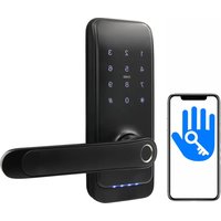
An electronic handle with access control simply limits access to protected areas for unauthorized persons. It is designed for both left and right doors, and the universal spacing of mounting screws allows for the use of an already installed mortise lock in most cases.
The handle body features a proximity key reader (Mifare 13.56 MHz) and a touch numeric keypad with Bluetooth module. Additionally, a fingerprint reader is installed above the numeric keypad.
After approaching the key fob to the reader, entering the correct PIN code, using a mobile application, or placing a finger on the fingerprint reader, the lock inside the handle is released.
2. SET CONTENTS
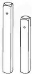
*
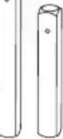
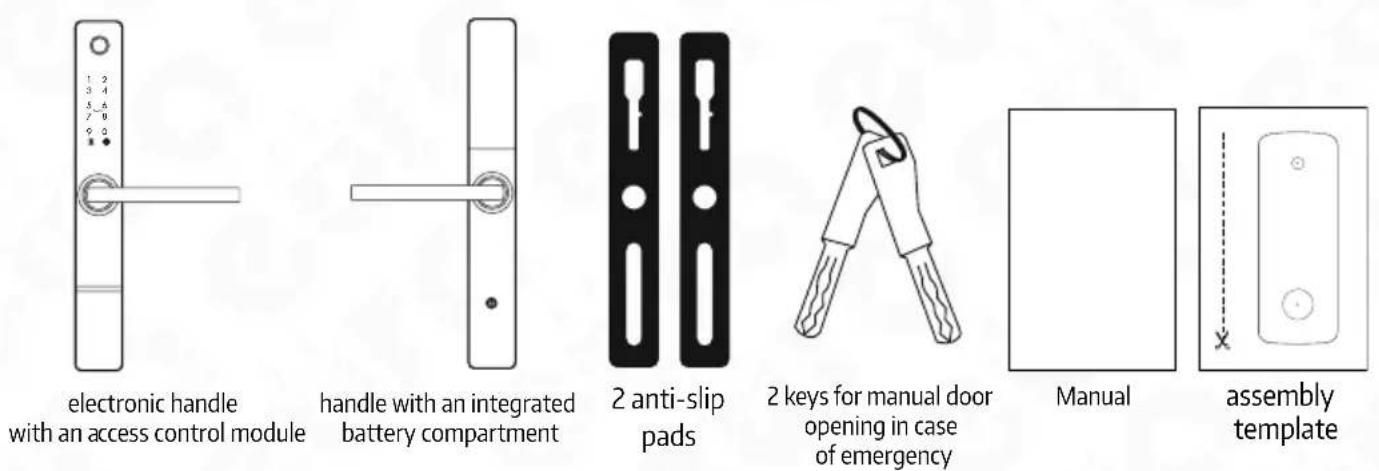
2 pins

pin locking
split pin
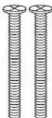
*
4 screws
for mounting
sleeves
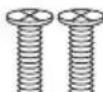
*
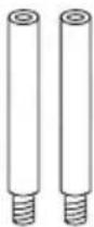
2 mounting
sleeves

additional
pin locking
bolt
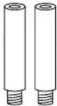
2 locking
sleeves
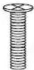
*
1 screw
for locking sleeve
* Note
The relevant accessories - pin, sleeves and tie bolts should be selected according to the door leaf thickness.
Fig. 1.
- STRUCTURE
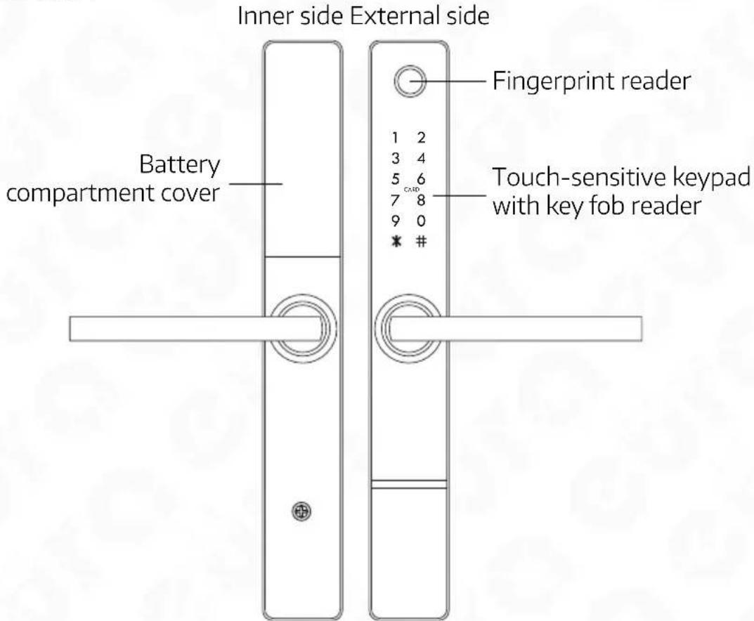
text_image
Inner side External side Battery compartment cover Fingerprint reader 1 2 3 4 5 6 7 8 9 0 * # Touch-sensitive keypad with key fob readerFig. 2. Construction
text_image
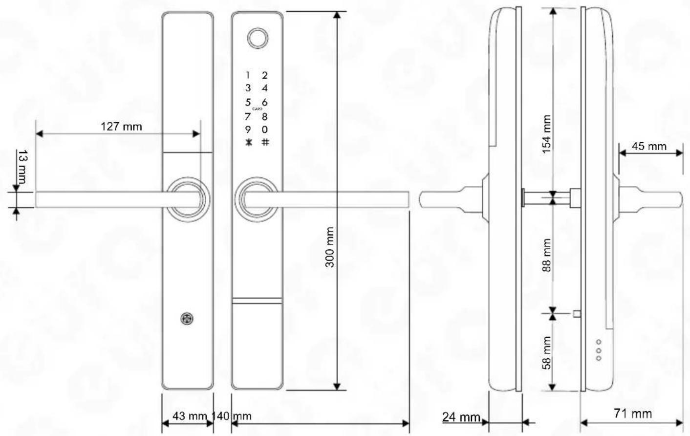
127 mm 13 mm 300 mm 43 mm 140 mm 24 mm 71 mm 154 mm 45 mm 88 mm 58 mmFig. 3. Dimensions
After receiving a signal from the electronic access control module, the servo motor unlocks the mechanical gearbox, allowing the door to be opened by normal operation of the external handle. The opening is indicated by a sound. The waiting period for handle operation is factory-set to approximately 5 seconds, after which the gearbox is re-locked and the lock returns to standby mode, waiting for the next signal from the electronic access control module.
From the inside of the room, the door can always be opened by simply pressing the handle. Once the door is closed, the latch mechanism immediately engages, preventing the door from being opened from the outside without a signal from the electronic access control module.
There is an emergency lock release feature that can be activated using a mechanical key, of which two copies are included in the kit. Additionally, the device has an access block function, which allows entry to the room only through the administrator application or emergency entry key.
5. MOUNTING THE ELECTRONIC HANDLE IN THE DOOR
The kit includes pins, sleeves, and screws for mounting the handle in doors with a thickness of 35-65 mm. During installation, the appropriate length of the supplied components must be selected.
Note!
Installation should be carried out with emergency keys on hand, which may be necessary if the door is accidentally locked with an unprogrammed lock. The lock should be installed on the open door leaf, and after installation and programming of the lock, a test of the device's operation should be carried out, also on the open door leaf.
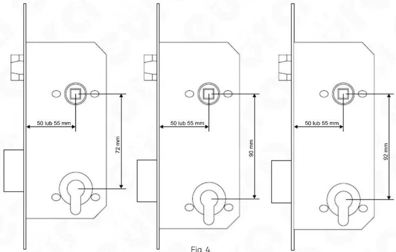
Example of locks installed in standard doors:
text_image
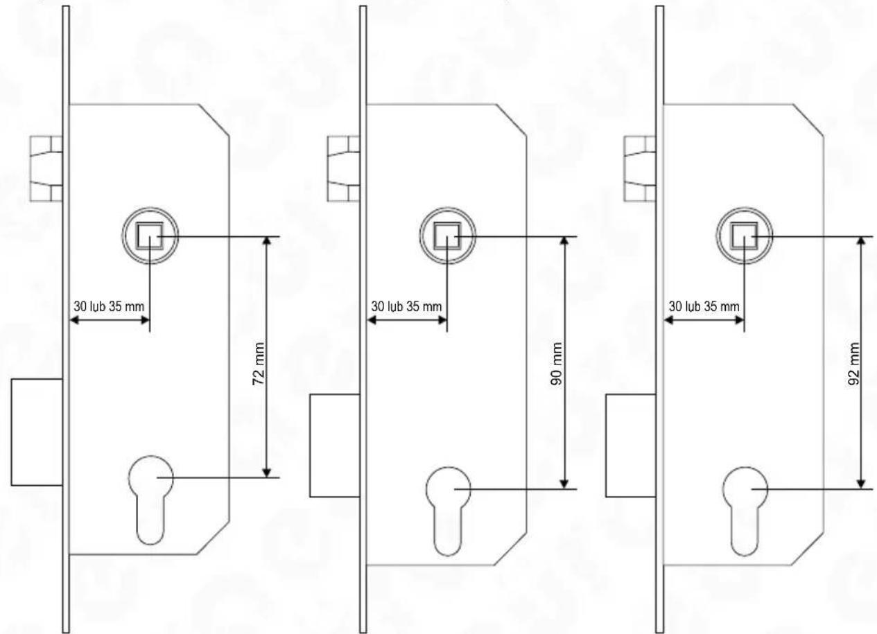
50 lub 55 mm 72 mm 50 lub 55 mm 90 mm 50 lub 55 mm 92 mm Fig. 4.Example of locks installed in doors with aluminum profile:
text_image
30 lub 35 mm 72 mm 30 lub 35 mm 90 mm 30 lub 35 mm 92 mmFig. 5.
5.1. SETTING HANDLE ORIENTATION (LEFT/RIGHT DOORS)
All electronic handles are universal and can be mounted on both left and right opening doors.
5.1.1 SETTING ORIENTATION - HANDLE FRONT
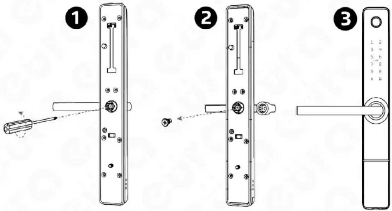
To determine the direction of the handle with built-in access control, loosen the mounting screw located on the inner side of the escutcheon (Fig. 6.), then change the direction of its position and tighten it again with the mounting screw.
text_image
Diagram showing three-step door lock assembly: pin, switch, and door handle with numbered partsFig. 6.
5.1.2 SETTING ORIENTATION - BACK OF ESCUTCHEON
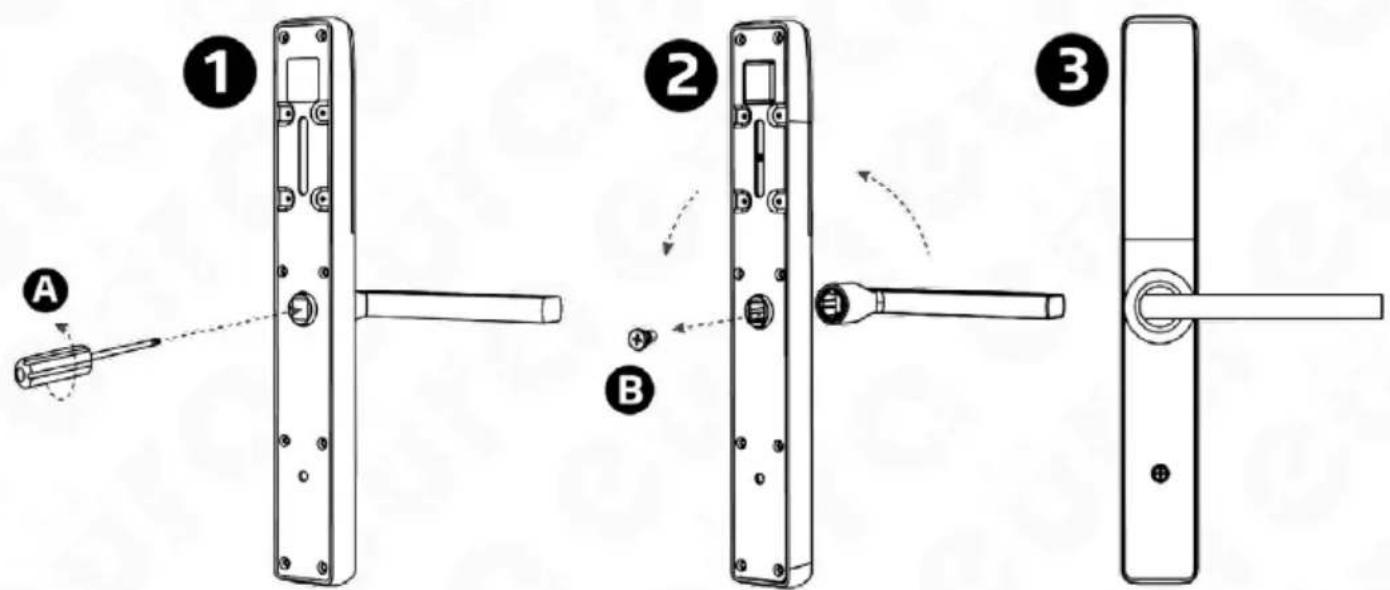
To set the direction of the handle with a built-in battery pocket, loosen the mounting screw located on the inner side of the escutcheon (Fig. 7.), then change the direction of its position and tighten it again with the mounting screw.
text_image
Diagram illustrating three-step door door repair process with labeled parts and tool pathFig. 7
5.2. INSTALLING THE BOLT IN THE ELECTRONIC HANDLE
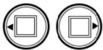
The bolt should be placed in the slot located in the device body marked with a triangle, and then the counter-locking washer included in the accessory kit should be installed.
Note:
When installing the bolt, remember to ensure that the slot in the lock body is facing towards the handle.
natural_image
Two identical circular icons with a square and arrow symbols inside, no text or numbers present.Fig. 8.
PREPARATION OF A REPLACEMENT BOLT
If you wish to use a different bolt than the one included in the set, you should:
acquire a bolt with dimensions of 8 × 8 mm, then measure the appropriate length and cut the bolt.
Note: The bolt must be cut to the correct length in order to eliminate the possibility of this element sliding during use. Otherwise, the bolt slot will be at risk of damage.
5.3 BATTERY INSTALLATION
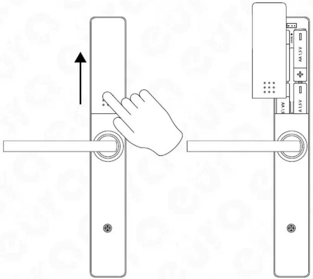
To install the battery in the battery compartment, slide the battery compartment cover upwards.
text_image
Diagram showing hand pressing down on a door lock mechanism with labeled components and directional arrowFig. 9
Attention!
- The device requires the use of alkaline batteries to function properly. Rechargeable batteries should not be used.
- It is recommended to install and program the handle with the door open. Once the proper operation is verified, the door can be closed.
- After inserting the batteries for the first time, the handle automatically enters the armed state. Therefore, batteries should only be inserted after the electronic handle has been mounted in the door. If the batteries were inserted earlier to open the door, the emergency key should be used, which is recommended to be kept on hand during installation.
The electromechanical handle is powered by 4 alkaline DC 1.5 V AA batteries and can work for approximately 1 year on one set of batteries. The battery status can be checked periodically through the application after synchronizing with the handle (via Bluetooth) or in real-time (by using WiFi gateways in the system).
5.4. INSTALLATION DIAGRAM
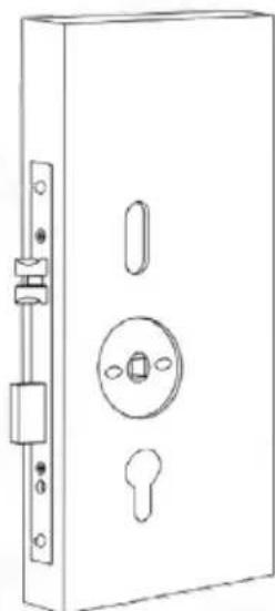
To install the electronic handle in a door:
natural_image
Line drawing of a door lock with handle, keyhole, and central knob (no text or symbols)Fig. 10.
text_image
Technical diagram showing a door handle assembly with three close-up views of the component and their corresponding tool path.Fig. 11.
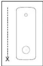
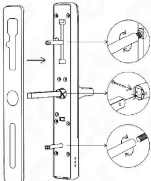
Existing mounting holes can be used, or new ones can be prepared according to the template included in the kit. To avoid damaging the mortise lock, it should be removed and verified that it complies with one of the standard samples shown in Fig. 4 or Fig. 5.
ATTENTION! It is also possible to install the handle in a different standard after verifying that installation in such a lock will not damage the lock or the electronic handle. Additionally, the cylinder insert should be removed from the lock. In most cases, the hole left after removing the cylinder insert will serve as the mounting track for the lower handle sleeve.
The installation sequence for the electronic handle is as follows:
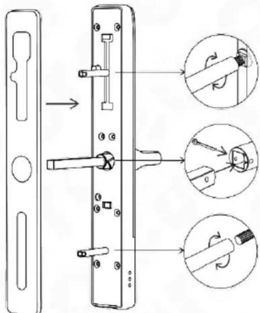
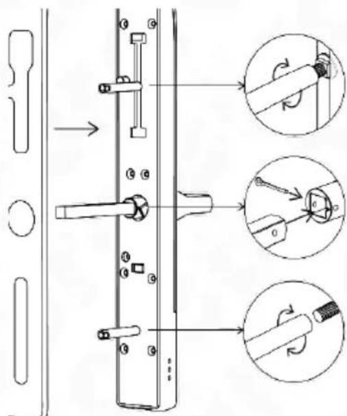
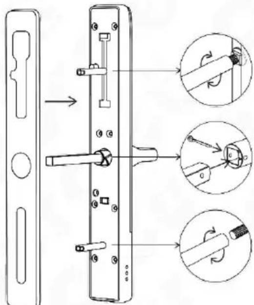
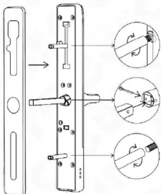
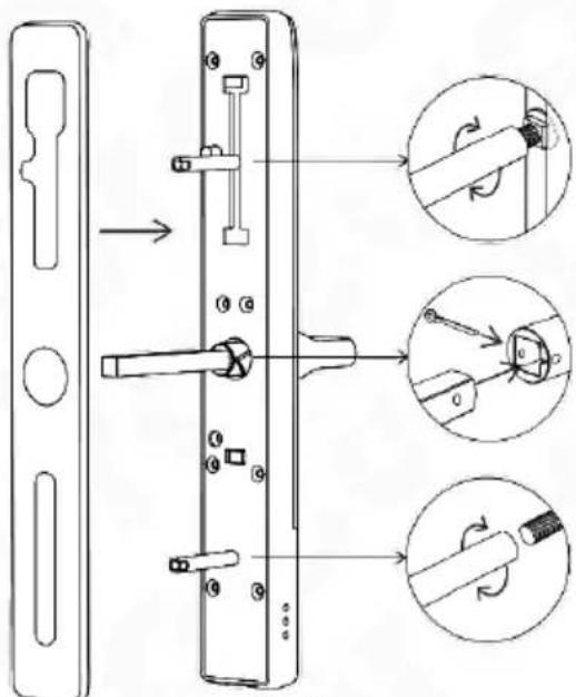
- According to Fig. 11, install the rubber washer and screw the mounting sleeves (two types of sleeves are included and should be selected according to the door thickness) onto the front body of the handle.
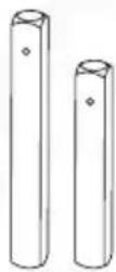
- Install the spindle into the handle socket and lock it with the plug (two types of spindles are included and should be selected according to the door thickness).
ATTENTION!
When mounting the plug in the spindle, ensure that the triangle symbol on the spindle socket is facing towards the handle grip. After placing the plug, adjust it to fit into the previously prepared spindle socket hole.
natural_image
Line drawing of a door lock assembly with handle and bracket (no text or symbols)Fig. 12.
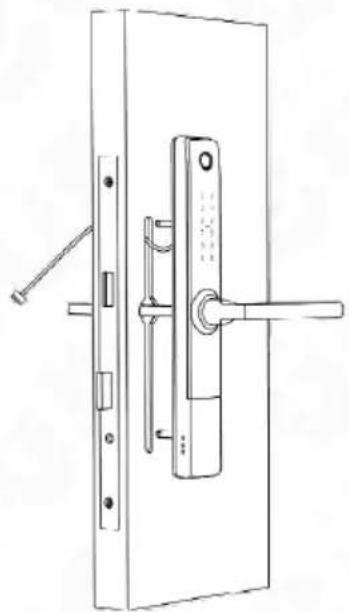
a. install the external part with connecting sleeves through the door leaf with the previously installed lock
b. route the connecting wires coming out of the external handle above the mortise lock
natural_image
Technical line drawing of a door handle with internal components, showing front and side views (no text or symbols)Fig. 13
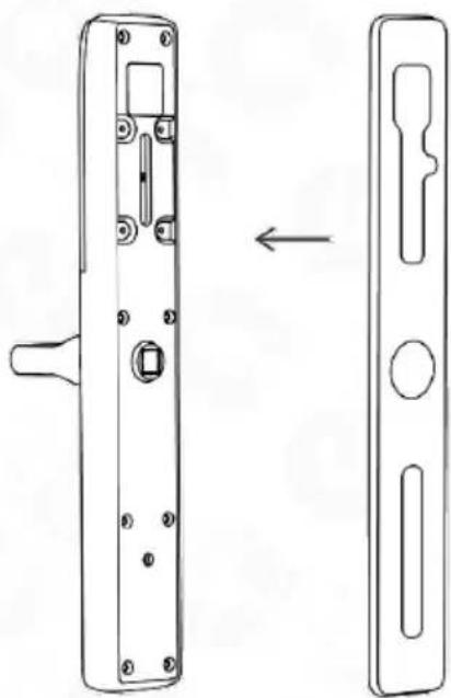
c. attach a rubber gasket to the back of the handle/shield
text_image
Technical diagram of a door lock mechanism with labeled components and a magnified inset showing the close-up detail.Fig. 14
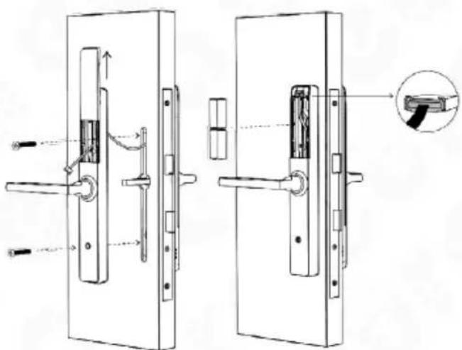
d. connect the wires on both sides of the handle (the connection socket is located under the battery compartment cover)
e. remove the battery compartment cover, then screw the back part of the handle to the front part using black securing screws
f. insert 4 AA alkaline batteries with a voltage of 1.5 V each into the power compartment.
natural_image
Technical line drawing of a door handle assembly with a lever and lock (no text or symbols)Fig. 15
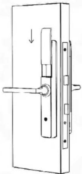
g. close the battery compartment. h. program the electronic door handle.
5.5 EMERGENCY ENTRANCE
text_image
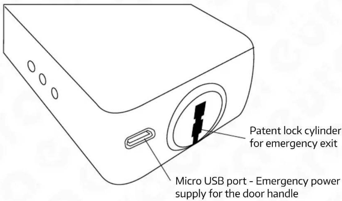
Patent lock cylinder for emergency exit Micro USB port - Emergency power supply for the door handleFig. 16.
In case of the need to enter the premises using the emergency key, insert the emergency key into the cylinder located at the bottom of the device on the access control side and turn the key to the right until resistance is felt. Then, by pressing the handle, one can enter the room.
Note!
There is a possibility of emergency power supply for the door handle in case the batteries run out. To do this, use the micro USB socket (DC 5 V) located at the bottom of the external door handle.
6. RESET THE HANDLE
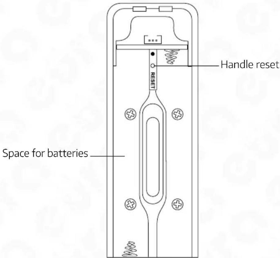
There is a reset button located under the battery cover of the handle. To perform a reset, press the reset button for 5 seconds, then enter the code 000# on the keypad. After the reset procedure is completed, the lock data will be restored to factory settings.
text_image
Handle reset RESET Space for batteriesFig. 17.
Note!
Performing a factory reset will disable the handle's operation in all applications to which the device has been added. However, the applications will continue to display the handle as an added device.
7. PROGRAMMING AND OPERATION OF THE ELECTRONIC HANDLE WITH ACCESS CONTROL
To program the ELH-20H4 electronic handle with access control, download the TTLock or TTHotel application from Google Play for Android devices or from the AppStore for iOS devices.

Detailed instructions for using the TTlock and TTHotel mobile applications are available on the www.eura-tech.eu website.
NOTE
If the device needs to be sent for service due to malfunction, the handle should be removed from the mobile application beforehand.
- TECHNICAL SPECIFICATION
| PARAMETERS | |||
| Supply voltage 6 V DC | |||
| Power supply type Alkaline batteries (4 x AA 1.5 V) | |||
| Current consumption - standby mode / operation | <18uA / 200 mA | ||
| Max. number of users Cards - 200, fingerprint | 200, PIN codes - 200, E-Key - no limit | ||
| Intended use in doors left-/right-sided | |||
| Housing material Zinc alloy | |||
| Release pulse duration 5-900 sek. | |||
| Bluetooth Tak | |||
| Max. radiated power (Bluetooth) <10mW | |||
| Operating frequency (Bluetooth) 2,4 GHz | |||
| Key code unit Yes, tactile | |||
| Max. radiated power (RFID) <5mW | |||
| Operating frequency (RFID) | Mifare 13,56 MHz | ||
| Permissible relative humidity | 0-95% | ||
| Operating temperature range | -35°C ~ +55°C | ||
| Recommended installation location | internal and external | ||
| Protection factor | IP65 | ||
| Maximum operating forces acting on the door plate | closing force or the force needed to start the movement of the leaf | 10 N | |
| hand operated fittings | maximum torque (Nm) | 1 Nm | |
| maximum force | 10 N | ||
| Dimensions of the external door plate (H x W x D) | 300x43x71 mm | ||
| Dimensions of the internal door plate (H x W x D) | 300x43x71 mm | ||
| Unit weight | 1200 g | ||
Note: The manufacturer reserves the right to make technical changes without prior notice
WARRANTY
As the only distributor of the Eura products, Eura-Tech is obliged to ensure efficient warranty and post-warranty service. In the countries where Eura-Tech has neither its own service network, nor DOOR-TO-DOOR service, the quality claims are dealt with by authorised distributors of the Eura products on the basis of the signed distribution agreements. Within the framework of such agreements, Eura-Tech will ensure financing of the possible repairs and delivery of spare parts.

Any used up electrical or electronical device must not be utilized or thrown away with other waste produced by household. In order to avoid harmful effect on natural environment and human health, the device must be utilized in places that are destined to do it. To get more information about place and method of safe utilization you should turn to local authorities or company specialized in recycling.
nr rej. BDO 000015700

ElektroEko
More information about recycling points can be found on www.elek troeko.pl
INHALTSVERZEICHNIS
- ALLGEMEINE EIGENSCHAFTEN UND ZWECK....34
- INHALTE FESTLEGEN ....34
- KONSTRUKTION....35
- FUNKTIONSPRINZIP....36
- EINBAU EINES ELEKTRONIKGRIFFS IN DIE TÜR....36
text_image
Diagram illustrating three-step door lock assembly: pinning, locking, and door handle application.Abb. 6.
text_image
Diagram illustrating three-step door repair or locking procedure: pinning, disassembly, and locking mechanism with labeled parts A, B, and 3.Abb. 7
5.2. EINBAU DES STIFTES IN DEN ELEKTRONIKGRIFF
text_image
Diagram showing hand pressing a door lock mechanism with directional arrow and component labelsAbb. 9
Aufmerksamkeit!
natural_image
Line drawing of a door lock with handle, keyhole, and central knob (no text or symbols)Abb. 10.
text_image
Technical diagram showing mechanical assembly with labeled parts and three progressive steps for tool manipulation.Abb. 11.
natural_image
Line drawing of a door lock mechanism with handle and bracket (no text or symbols)Abb. 12.
natural_image
Technical line drawing of a door handle with internal components, showing front and side views (no text or symbols)Abb. 13
text_image
Technical diagram of a door lock mechanism with labeled components and a magnified inset showing the close-up detail.Abb. 14
natural_image
Technical line drawing of a door lock mechanism with handle and lock (no text or symbols)Abb. 15
text_image
Diagram illustrating three steps of door lock assembly: pinning, locking, and door lock control.Fig. 6.
text_image
Diagram illustrating three-step door lock assembly steps with labeled components and directional arrowsFig. 7
natural_image
Two identical circular icons with a central square and arrow, no text or symbols present.Fig. 8.
text_image
Diagram showing hand pressing a door lock mechanism with directional arrow and component labelsFig. 9
Atención!
natural_image
Line drawing of a door lock with handle, keyhole, and central knob (no text or symbols)Fig. 10.
text_image
Technical diagram showing a door lock mechanism with labeled components and three progressive assembly steps.Fig. 11.
natural_image
Line drawing of a door lock assembly with handle and bracket (no text or symbols)Fig. 12.
natural_image
Technical line drawing of a door handle with internal components, showing front and side views (no text or symbols)Fig. 13
text_image
Technical diagram of a door lock mechanism with labeled components and a magnified inset showing the close-up detail.Fig. 14
natural_image
Technical line drawing of a door handle assembly with a lever and lock (no text or symbols)Fig. 15
To program the ELH-20H4 electronic handle with access control, download the TTLock or TTHotel application from Google Play for Android devices or from the AppStore for iOS devices.

text_image
Diagram showing three steps of a door handle assembly: opening, adjusting, and closing with a key.Fig. 6.
5.1.2 ORIENTATION DU RÉGLAGE - DOS DE L'ÉCUSSON
text_image
Diagram illustrating three-step door lock assembly steps with labeled components and directional arrowsFig. 7
5.2. INSTALLATION DU BOULON DANS LA POIGNÉE ÉLECTRONIQUE
text_image
Diagram illustrating door lock mechanism with hand gesture and battery terminal labelsFig. 9
Attention!
natural_image
Line drawing of a door lock with handle, lock, and keyhole (no text or symbols)Fig. 10.
text_image
Technical diagram showing a door lock mechanism with labeled components and three progressive assembly steps.Fig. 11.
natural_image
Line drawing of a door lock mechanism with handle and bracket (no text or symbols)Fig. 12.
natural_image
Technical line drawing of a door handle with internal components, showing front and side views (no text or symbols)Fig. 13
text_image
Technical diagram of a door lock mechanism with labeled components and a close-up inset showing the detail view.Fig. 14
natural_image
Technical line drawing of a door handle assembly with a lever and lock (no text or symbols)Fig. 15
text_image
Two QR codes with Android and Apple logos above each, likely for mobile app scanning.text_image
Diagram showing three-step door lock assembly: pinning, locking, and door handle with numbered parts.Fig. 6.
text_image
Diagram illustrating three-step door repair or locking procedure: (1) pinning, (2) disassembly with screwdriver, and (3) lock mechanism.Fig. 7
text_image
Diagram showing hand pressing a door lock mechanism with directional arrow and component labelsFig. 9
Attenzione!
natural_image
Line drawing of a door lock with handle, keyhole, and central knob (no text or symbols)Fig. 10.
text_image
Technical diagram showing a door lock assembly with three progressive steps for tool application, including rotation and adjustment views.Fig. 11.
natural_image
Line drawing of a door lock mechanism with handle and bracket (no text or symbols)Fig. 12.
natural_image
Technical line drawing of a door handle assembly showing front and side views (no text or symbols)Fig. 13
text_image
Technical diagram showing two door lock assembly steps with labeled components and a magnified detail view of the final component.Fig. 14
natural_image
Technical line drawing of a door lock mechanism with handle and lock (no text or symbols)Fig. 15
Eura-Tech Sp. z o.o. hereby declares that the radio device type - ELH-20H4 electronic door handle with access control - complies with the Directive 2014/53/EU.
Find the full text of the EU declaration at:
www.eura-tech.eu
Eura-Tech Sp. z o.o. reserves the right to change technical parameters and modify the operating manual without notice. It would also
like to inform that the most recent version of the operating manual is available on the
www.eura-tech.eu website,
on the sub-page dedicated to the specific product.
The EU Declaration of Conformity can be found at
http://www.eura-tech.eu
Eura-Tech Sp. z o.o. reserves the right to change technical parameters and modify the operating manual without notice. It would also
like to inform that the most recent version of the operating manual is available on the
www.eura-tech.eu
website, on the sub-page dedicated to the specific product.
The EU Declaration of Conformity can be found at
http://www.eura-tech.eu