ELH-01H4 - Lock Eura - Free user manual and instructions
Find the device manual for free ELH-01H4 Eura in PDF.


User questions about ELH-01H4 Eura
0 question about this device. Answer the ones you know or ask your own.
Ask a new question about this device
Download the instructions for your Lock in PDF format for free! Find your manual ELH-01H4 - Eura and take your electronic device back in hand. On this page are published all the documents necessary for the use of your device. ELH-01H4 by Eura.
USER MANUAL ELH-01H4 Eura
KARTA GWARANCYJNA 17
UWAGI WSTĘPNE
natural_image
Simple line drawing of a door handle with a scroll wheel (no text or symbols)natural_image
Two identical black rectangular electronic components with white plastic outlines and mounting holes (no text or symbols)natural_image
Empty white rectangle with black border (no text or symbols)Instrukcja
natural_image
Simple line drawing of a rectangular object with two circular holes and a vertical dashed line with an 'X' at the bottom left (no text or symbols on the object itself)szablon montażowy
* 2 trzpienie
natural_image
Illustration of four different types of screws (no text or symbols present)text_image
Diagram of a door switch mechanism with labeled parts A, B, and C, showing internal components and directional arrows.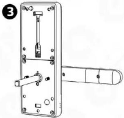
natural_image
Technical line drawing of a door handle assembly with no visible text or symbolsRys. 6.
5.1.2 USTAWIENIE ORIENTACJI - TYŁ SZYLDU
text_image
Diagram of a remote control device with labeled parts and a cartoon character inside, showing internal components and a red arrow indicating motion.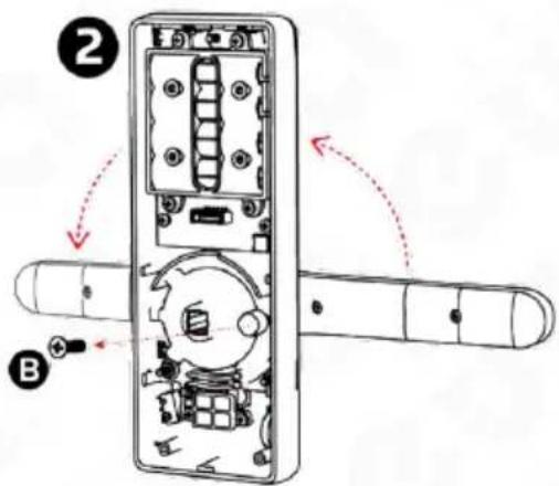
text_image
Technical diagram of a door panel with labeled components and directional arrows indicating movement or assembly.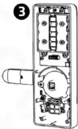
text_image
③Rys. 7
5.2. MONTAŻ TRZPIENIA W KLAMCE ELEKTRONICZNEJ
text_image
Diagram showing hand valve mechanism and battery panel with power rating labelsRys. 9
Uwaga!
natural_image
Line drawing of a rectangular door with a circular vent and side lock (no text or symbols)Rys. 10.
text_image
Technical diagram of a door lock with labeled components and an inset showing cable connection detailRys. 13
natural_image
Line drawing of a door lock assembly with handle, door, and wall-mounted lock (no text or symbols)Rys. 14
natural_image
Line drawing of a door handle with lever and lock (no text or symbols)Rys. 15
Please read these operating instructions carefully before installing, connecting and using the unit. In the case of any problems with understanding the content of this document, please contact the device seller.
Installation and start-up of the device by the user are possible if adequate tools are used. Nevertheless, it is recommended to have the device installed by qualified personnel.
Because of the possible damage to the handle with access control:
-the device should never be installed in doors with a door closer,
- the door in which the device is going to be installed should be correctly installed and adjusted along the door frame,
- the door leaf must close easily (without springing) and the maximum operating forces acting on the device should exceed the threshold values specified in the device specification provided in this manual,
Handles with access control should not be installed in saunas, refrigerated warehouses and other premises, where relative humidity and ambient temperature exceed the threshold values indicated in the technical specification of the device.
For added security, it is recommended to install the patented insert, which also acts as an additional emergency entry option.
The manufacturer shall not be liable for damage which may occur as a result of incorrect installation or operation, as well as unauthorised repairs and modifications.
Remember to:
- use the device according to its intended use, keep it away from moisture and fire, do not throw into fire, avoid impacts, do not crush and expose the device to mechanical damage,
- do not clean the device with water, solvents or other chemicals,
- clean the housing only with the power supply cut off, use only a wet cloth for cleaning and wait until the housing is completely dry after cleaning,
- do not carry out unauthorised modifications or repairs,
Caution!
Devices with a protection degree equal to or higher than IP44 may be installed outdoors (e.g. doorbell buttons, outdoor video intercom panels, cameras, etc.). Information about the protection degree is available in the technical specification of the device.
1. GENERAL CHARACTERISTICS AND INTENDED USE
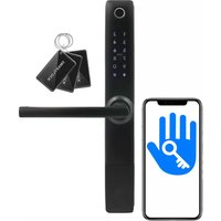
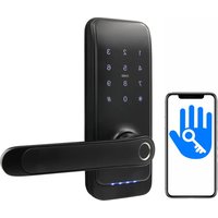
The electronic handle with access control provides a simple method of limiting access of unauthorised persons to protected premises. It is designed for both left- and right-sided doors, and the universal distance of fixing screws of 40-45 mm usually allows to use a mortise lock already installed in the door.
The handle body includes a contactless key fob reader (Mifare 13.56 MHz) and a numeric keypad with a Bluetooth module. A fingerprint reader is additionally installed in the handle, on the access control side.
The bolt inside the lock is released when a key fob is placed close to the reader, the correct PIN code is entered, the mobile application is used or a finger is placed on the fingerprint reader.
2. SET CONTENTS
text_image
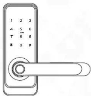
1 2 3 4 5 6 7 8 9 * 0 #electronic handle with an access control module
natural_image
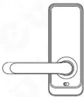
Simple line drawing of a door handle with a circular button (no text or symbols)handle with an integrated battery compartment
natural_image
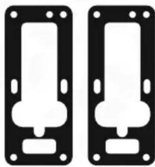
Two identical black rectangular electronic components with white plastic caps and mounting holes (no text or symbols)2 anti-slip pads
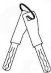
2 keys for manual door opening in case of emergency
natural_image
Empty white rectangle with black border (no text or symbols)Manual
natural_image
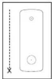
Simple line drawing of a rectangular device with two circular holes and a vertical dashed line marked with an 'X' at the bottom left (no text or symbols on the device itself)assembly template
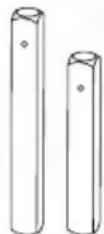
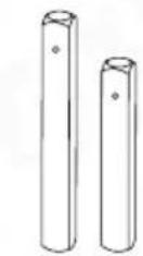
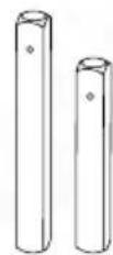
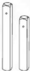
* 2 pins
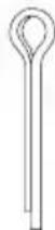
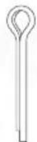
pin locking
split pin

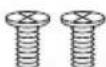
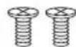
4 screws fixing
the housing base to the
handle with an integrated
battery compartment
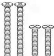
natural_image
Illustration of four different types of screws (no text or symbols present)* 4 screws for mounting sleeves
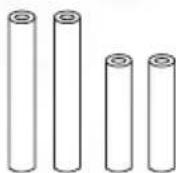
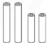
* 4 mounting sleeves

additional
pin locking
bolt
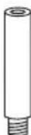
* 1 locking sleeve
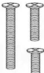
3 bolts for
the locking sleeve
* Note
The relevant accessories - pin, sleeves and tie bolts should be selected according to the door leaf thickness.
Fig. 1.
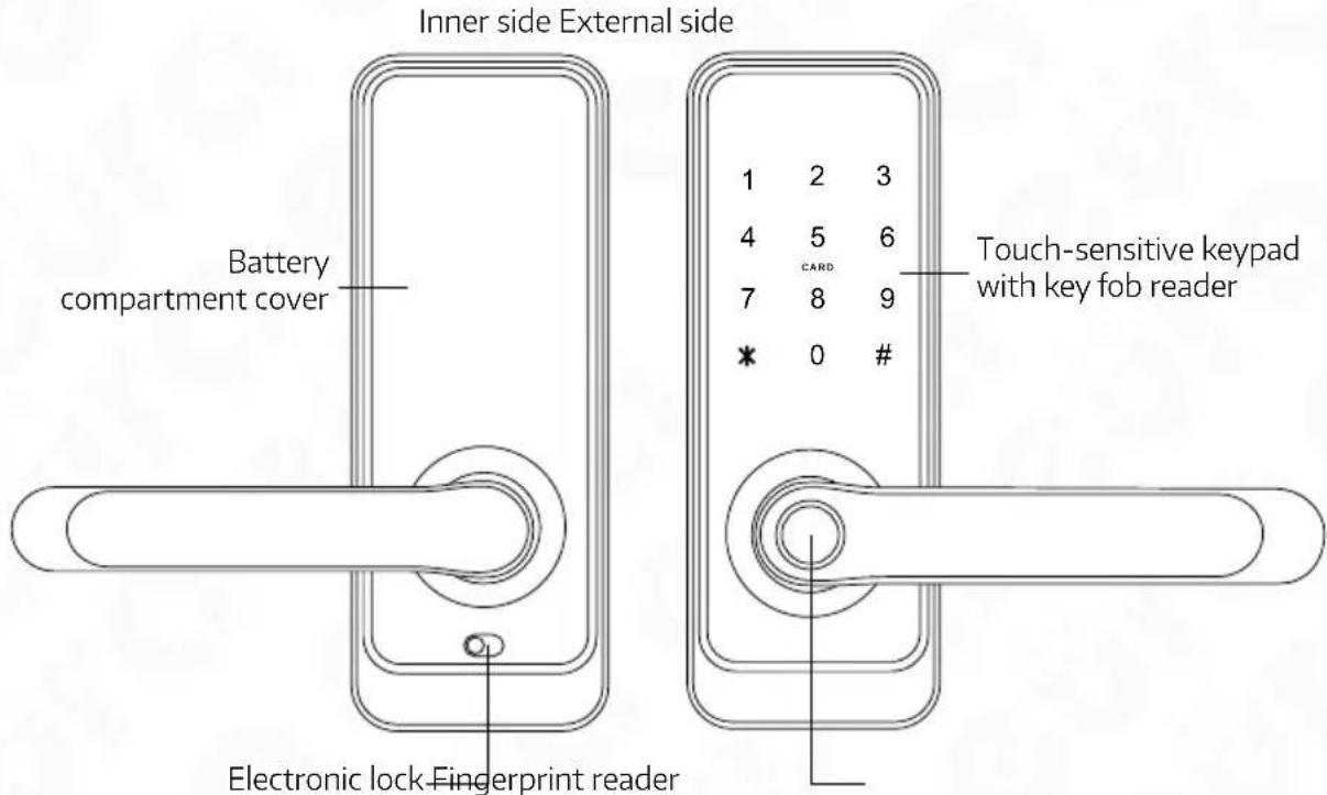
3. STRUCTURE
text_image
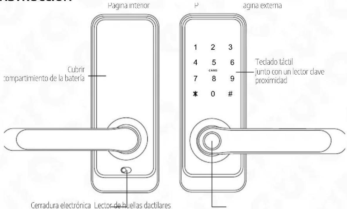
Inner side External side Battery compartment cover Electronic lock-Fingerprint reader 1 2 3 4 5 6 CARD 7 8 9 * 0 # Touch-sensitive keypad with key fob readerFig. 2. Structure
text_image
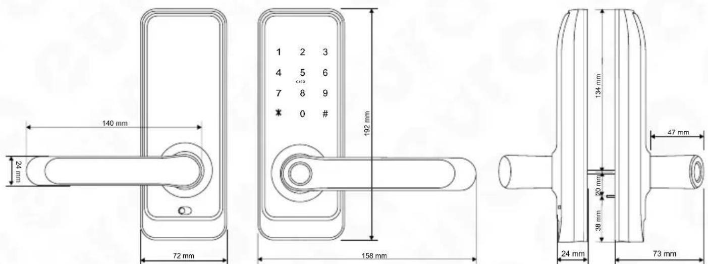
140 mm 24 mm 72 mm 192 mm 158 mm 134 mm 47 mm 24 mm 73 mm 20 mm 38 mmFig. 3. Dimensions
4. PRINCIPLE OF OPERATION
When a pulse is transmitted from the electronic access control module, the servomotor releases the mechanical gear, thus enabling the door to be opened by pressing the outer part of the handle. The door opening is indicated by a sound. The handle pressing waiting period is factory set at approx. 5 seconds, and after this time the gear is locked again and the lock enters standby mode, awaiting the next pulse from the electronic access control module.
The door can always be opened from the inside (on the premise side) by simply pressing the handle. When the open door is closed, the ratchet mechanism is operated immediately, preventing the door from being open from the outside without a pulse sent from the electronic access control module.
The lock can be open in an emergency using a simple mechanical key, and two such keys are provided in the kit.
The device is additionally provided with an access lock function, which allows the premise only to be entered using the administrator application or the emergency entry key.
5. FITTING THE ELECTRONIC DOOR HANDLE IN A DOOR
The kit is provided with pins, sleeves and bolts enabling handle installation in 35\~65 mm thick doors. Select the appropriate length of the provided elements during installation.
Caution!
For increased safety, it is recommended to install electronic handles with access control in rebated doors. It is also recommended to install the patented insert in a mortise lock, which allows the lock to be open using a key in the case of damage to the electronic handle. Installation should be performed while carrying the emergency keys which may be required if the door is shut locked with the lock not programmed yet. The lock installation should be performed with the door leaf open and once the installation is done and the lock is programmed, perform a test run of the device, also with the door leaf open.
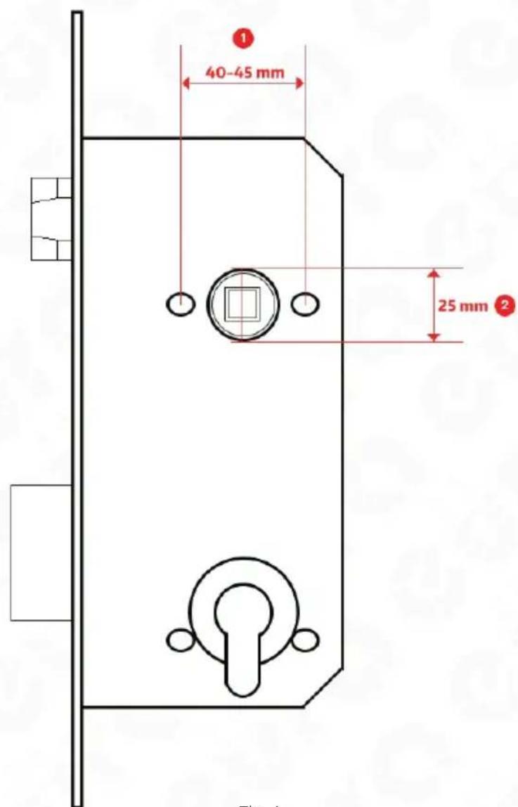
text_image
40-45 mm 25 mmFig. 4.
Caution!
It is recommended to install the handle using a lock with the following spacing: 72 mm, 90 mm or 92 mm. A part of the hole dedicated for the patented insert may be covered using the appropriate installation mask. Dedicated masks for the relevant distance should be purchased separately.
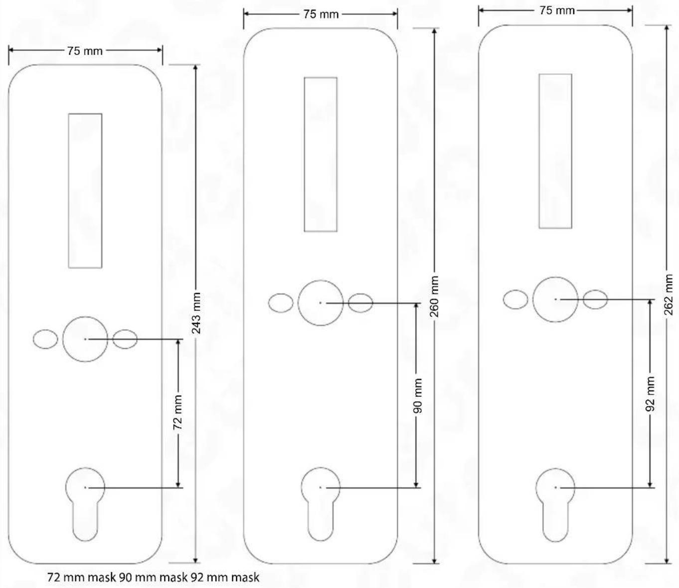
Fig. 5.
5.1. HANDLE ORIENTATION SETTING (LEFT/RIGHT-SIDED DOOR)
All electronic handles are versatile and may be installed in doors opened to the left and to the right.
5.1.1. ORIENTATION SETTING - HANDLE FRONT
In order to determine the opening direction of the handle with built-in access control:
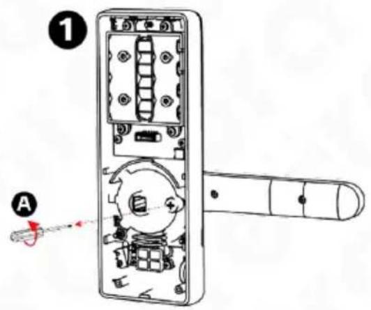
- unscrew the 4 bolts from the base of the door plate, holding the cover (Fig. 6),
- remove the cover (Fig. 6, position 1-A),
- remove the locking screw (Fig. 6, position 2-B),
- move the handle to the desired opening direction (Fig. 6, position 2-C)
- tighten the locking screw,
- replace the cover and fasten the fixing screws (Fig. 6, position 3)
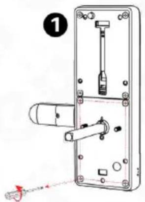
text_image
1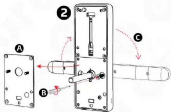
text_image
Diagram of a door switch mechanism with labeled parts A, B, and C, showing internal components and directional arrows.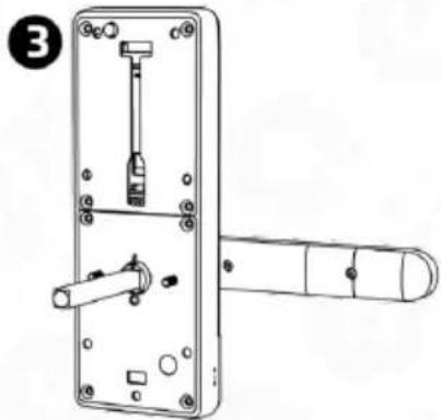
natural_image
Technical line drawing of a door handle assembly with screwdriver and lever (no text or symbols)Fig. 6.
5.1.2 ORIENTATION SETTING - BACK OF THE DOOR PLATE
In order to set the opening direction of a handle with a built-in battery compartment:
- unscrew the locking screw located next to the pin seat (Fig. 7, position 1-A)
- set the handle grip in the desired direction (Fig. 7, position 2)
- once the direction is set, tighten the screw setting the handle direction (Fig. 7, position 3).
text_image
Diagram of a remote control device with labeled parts and a red indicator arrow indicating motion direction.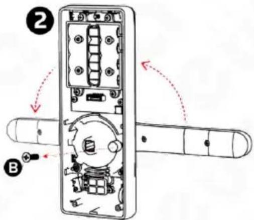
text_image
Diagram of a door handle with labeled parts and directional arrows indicating movement or assembly.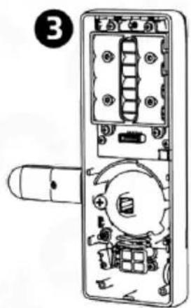
natural_image
Diagram of a door handle with internal components and a numbered label (3), no readable text or symbols present.Fig. 7
5.2. PIN FITTING INSIDE THE ELECTRONIC HANDLE
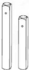
The pin should be placed inside the seat available in the device body, labelled with a triangle, and the locking split pin available in the accessory set should be attached next.
Note!
When installing the pin remember that the element located in the lock body should be directed towards the bottom of the handle.
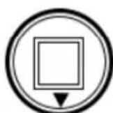
Fig. 8.
PREPARATION OF A REPLACEMENT PIN
If the user wants to use a pin other than the pin provided with the kit: obtain a 8 x 8 mm pin, measure the required distance and cut the pin accordingly.
Note: The pin must be cut to the appropriate length such that the pin cannot move during use, otherwise the pin seat will be susceptible to damage.
5.3 BATTERY INSTALLATION
In order to place a battery inside the battery compartment, lift the battery compartment cover in the middle, at the top, using a screwdriver.
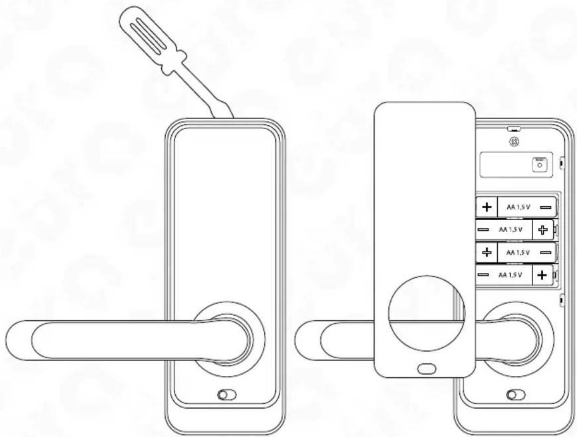
text_image
Diagram showing a hand switch and battery compartment with labeled power supply (AA 1.5V) for door lock status.Fig. 9
Caution!
- Alkaline batteries are required to ensure correct operation of the device, do not use rechargeable batteries.
- It is recommend to carry out the handle installation and programming with the door leaf open, the door leaf may be closed once the correct operation of the handle is verified.
- When a battery is inserted for the first time, the handle will be armed automatically, thus remember to place the batteries only once the electronic handle is installed in the door leaf. If batteries were inserted prior in order to open the door, use the emergency key, which should be available during the installation.
The electromechanical handle is supplied using 4 DC 1.5 V AA type alkaline batteries and can operate for approximately 1 year using one set of batteries. The battery charging status may be reviewed in the application, after periodic synchronisation with the handle (via Bluetooth) or in real time (if Wi-Fi gates are used in the system).
5.4. INSTALLATION DIAGRAM
In order to install the electronic handle in the door:
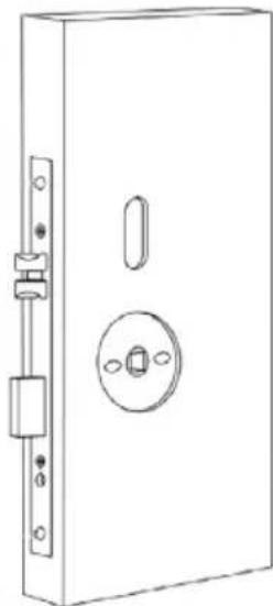
natural_image
Line drawing of a rectangular door with a circular vent and side lock (no text or symbols)Fig. 10.
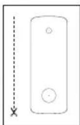
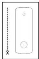
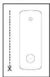
Use the existing holes or prepare the installation holes according to the jig provided in the kit.
In order to drill the installation holes, remove the lock from the door, make sure it complies with the standard indicated in Fig. 3 and next drill the holes:
a. two ca. 12 mm diameter holes used to screw the internal and the external part of the handle together.
b. one 25 mm diameter hole used to hide the pin seat, including the locking split pin.
c. the third, longitudinal hole (see the jig) is made in order to pass the cable connecting the front part of the door plate with its rear part and for the possible use of the locking pin.
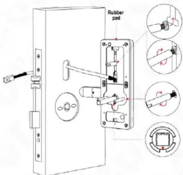
text_image
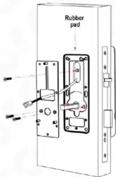
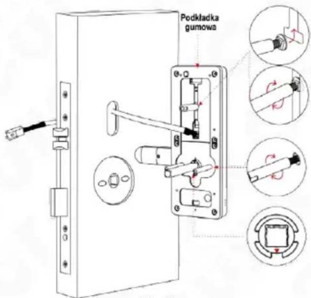
Rubber padFig. 11.
d. place the rubber pad according to the drawing and screw the sleeves to the front body of the handle,
e. pass the connecting cables exiting the external part of the door plate above the mortise lock,
f. pass the external part including the connecting sleeves through the door leaf with the previously installed lock
text_image
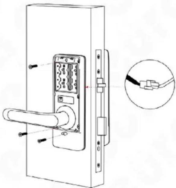
Rubber padFig. 12.
g. unscrew the fixing base from the external part of the handle and place a rubber pad on the fixing base,
h. next, pass the connecting cables,
i. finally, tighten the fixing base using the sleeves of the internal part of the handle
natural_image
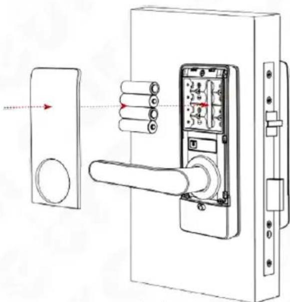
Technical line drawing of a door handle with attached circuit breaker and connector, plus an inset showing cable connection detail (no text or symbols)Fig. 13
j. connect the cables connecting both sides of the handle, k. remove the battery compartment cover, tighten the rear part of the body to the fixing base
natural_image
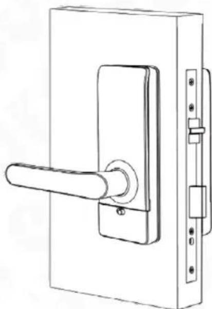
Line drawing of a door lock assembly with handle, door, and wall-mounted lock (no text or symbols)Fig. 14
I. insert 4 1.5 V AA type alkaline batteries into the power supply compartment,
m. close the battery compartment,
natural_image
Line drawing of a door handle with lever and lock (no text or symbols)Fig. 15
n. program the electronic handle.
5.5 EMERGENCY ENTRY
text_image
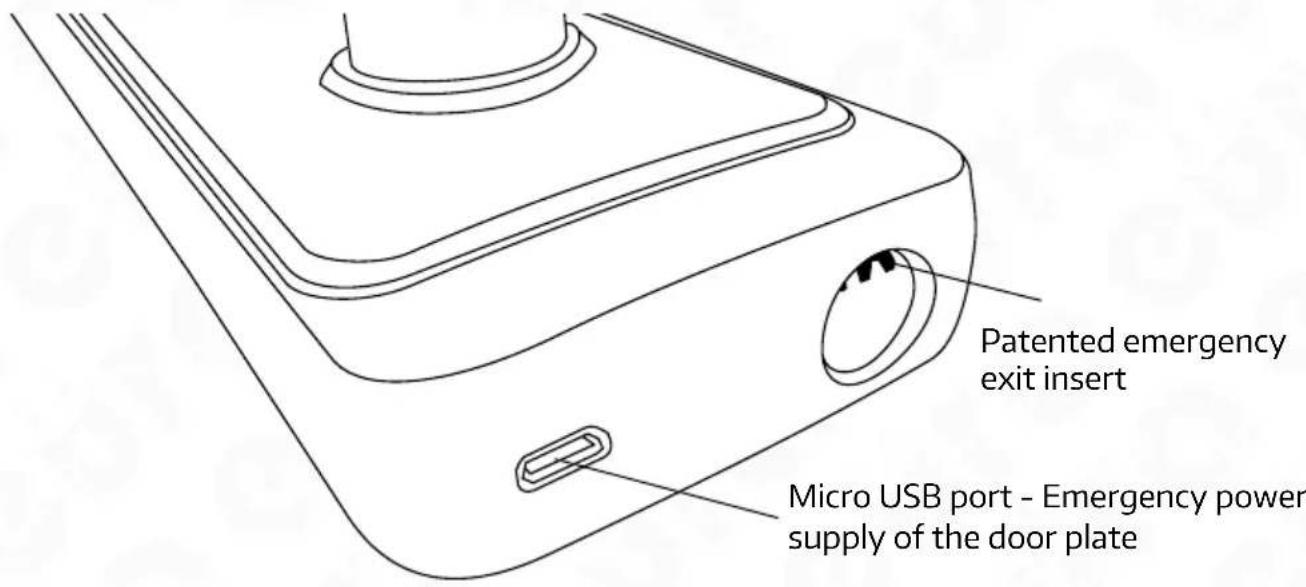
Patented emergency exit insert Micro USB port - Emergency power supply of the door plateFig. 16.
If it is necessary to enter the premise using the emergency key, insert the emergency key into the insert present at the bottom of the device, on the side of the access control panel and turn the key clockwise until resistance is felt. The premise can then be entered by pressing the handle.
Note!
The handle may be provided with emergency power supply if the batteries are discharged. To do this, use the micro USB port (DC 5 V) available in the bottom part of the external handle.
6. ELECTRONIC LOCK
text_image
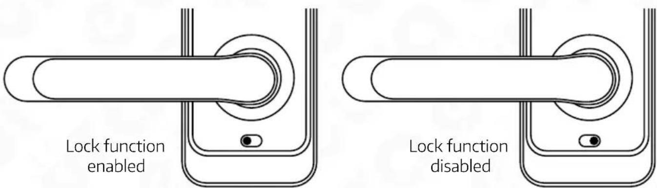
Lock function enabled Lock function disabledFig. 17.
-
In order to activate the electronic lock function, activate the 'privacy lock' function in the application;
-
Once the button is located at the red position, the system is locked and may be unlocked only using the administrator application or a mechanical key.
7. HANDLE RESET
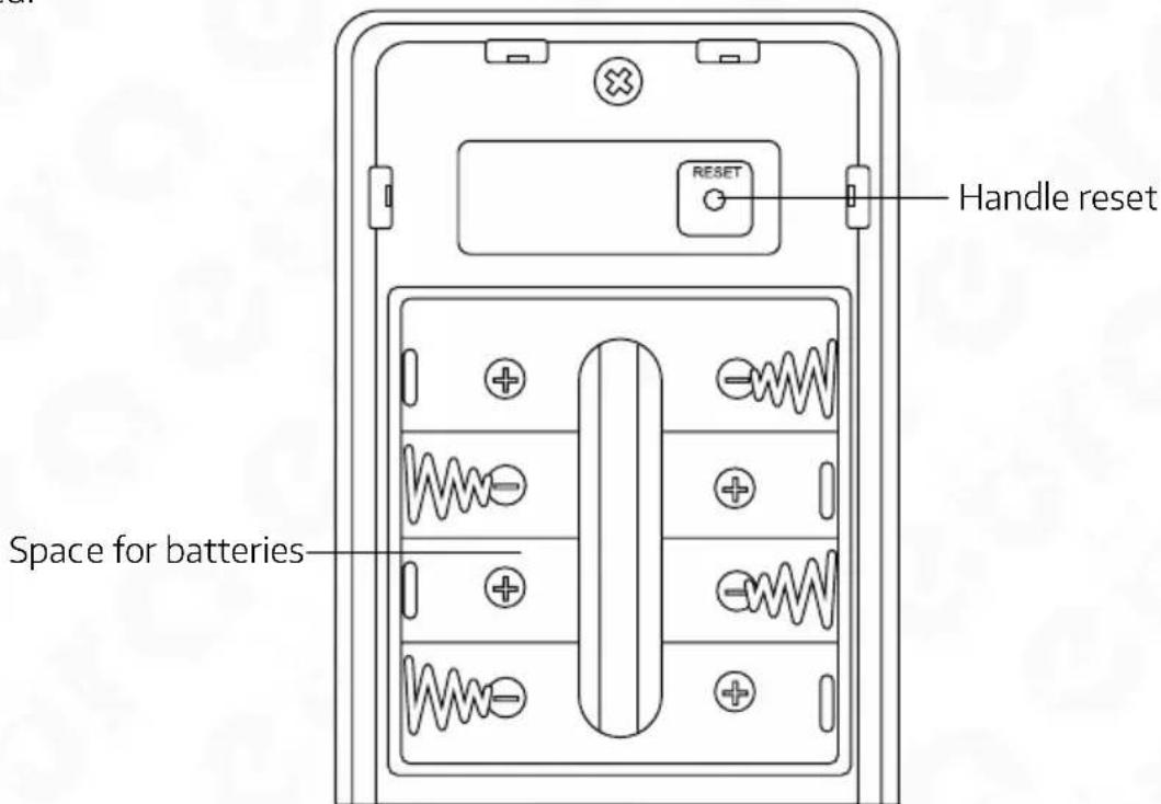
The handle reset button is located under the battery compartment cover. In order to reset the handle, press and hold the reset button for 5 seconds and enter the 000# code using the key code unit panel. Once the reset procedure has been performed, the factory settings of the lock are restored.
text_image
Space for batteries RESET Handle resetFig. 18.
Note!
Performing a factory reset disables handle support in all applications, to which the device has been added. At the same time, the devices will continue to display the handle as an added device.
8. PROGRAMMING AND OPERATION OF THE ELECTRONIC HANDLE WITH ACCESS CONTROL
In order to program the ELH-01H4 electronic handle with access control, download the TTLock or TTHotel applications from GooglePlay for Android system devices or from AppStore for iOS system devices.
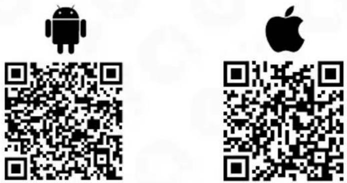
Comprehensive user manuals for the TTlock and TTHotel mobile applications are available at www.eura-tech.eu.
NOTE
In the case of a malfunction, if the device has to be sent to a service station, remove the handle from the mobile application first.
- TECHNICAL SPECIFICATION
| PARAMETR | |||
| Supply voltage 6 V DC | |||
| Power supply type Alkaline batteries (4 x AA 1.5 V) | |||
| Current consumption - standby mode / operation | <18 uA / 200 mA | ||
| Max. number of users Cards - 200, fingerprint | 200, PIN codes - 200, E-Key - no limit | ||
| Intended use in doors left-/right-sided | |||
| Housing material Zinc alloy | |||
| Release pulse duration 5-900 sec. | |||
| Bluetooth Yes | |||
| Max. radiated power (Bluetooth) <10 mW | |||
| Operating frequency (Bluetooth) 2.4 GHz | |||
| Key code unit Yes, tactile | |||
| Max. radiated power (RFID) <5 mW | |||
| Operating frequency (RFID) Mifare 13.56 MHz | |||
| Permissible relative humidity | 0-95% | ||
| Operating temperature range -35°C ~ +55°C | |||
| Recommended installation location | internal and external | ||
| Protection factor IP55 | |||
| Maximum operating forces acting on the door plate | closing force or force required to initiate movement of the leaf | 10 N | |
| manually operated fittings | maximum torque (Nm) | 1 Nm | |
| maximum force | 10 N | ||
| Dimensions of the external door plate (H x W x D) | 195x73x72 mm | ||
| Dimensions of the internal door plate (H x W x D) | 195x73x72 mm | ||
| Unit weight | 1200 g | ||
Note: The manufacturer reserves the right to make technical changes without prior notice
WARRANTY
As the only distributor of the Eura products, Eura-Tech is obliged to ensure efficient warranty and post-warranty service. In the countries where Eura-Tech has neither its own service network, nor DOOR-TO-DOOR service, the quality claims are dealt with by authorised distributors of the Eura products on the basis of the signed distribution agreements. Within the framework of such agreements, Eura-Tech will ensure financing of the possible repairs and delivery of spare parts.

ElektroEko
Any used up electrical or electronical device must not be utilized or thrown away with other waste produced by household. In order to avoid harmful effect on natural environment and human health, the device must be utilized in places that are destined to do it. To get more information about place and method of safe utilization you should turn to local authorities or company specialized in recycling.
nr rej. BDO 000015700
More information about recycling points can be found on www.elek troeko.pl
INHALTSVERZEICHNIS
natural_image
Simple line drawing of a door handle with a scroll wheel (no text or symbols)natural_image
Two identical black rectangular panels with white internal cutouts, no text or symbols visible.natural_image
Empty white rectangle with black border (no text or symbols)Anweisung
natural_image
Simple line drawing of a rectangular object with two circular holes and a vertical dashed line with an 'X' at the bottom left (no text or symbols)Vorlage Montage
* 2 Stifte
natural_image
Illustration of four different types of screws (no text or symbols present)natural_image
Illustration of five different types of cylindrical and standard screw components (no text or symbols)text_image
Diagram showing three-step assembly of a door lock mechanism with labeled parts and directional arrows indicating movement.Abb. 6.
text_image
Diagram showing three-step door lock mechanism with labeled parts and directional arrowsAbb. 7
5.2. EINBAU DES STIFTES IN DEN ELEKTRONIKGRIFF
natural_image
Line drawing of a hand handle and smartphone lock panel with a screwdriver, showing internal control buttons (no text or symbols)Abb. 9
Aufmerksamkeit!
natural_image
Line drawing of a rectangular door with a circular vent and side lock (no text or symbols)Abb. 10.
natural_image
Technical line drawing of a door handle with attached circuit breaker and connector, plus an inset showing cable connection detail (no text or symbols)Abb. 13
natural_image
Technical line drawing of a door lock assembly with handle, door panel, and wall-mounted door (no text or symbols)Abb. 14
natural_image
Line drawing of a door handle with lever and lock (no text or symbols)Abb. 15
natural_image
Simple line drawing of a hand holding a smartphone (no text or symbols)natural_image
Two identical black rectangular electronic components with white plastic outlines and mounting holes (no text or symbols)natural_image
Empty white rectangle with a thin black border (no text or symbols)Instrucción
natural_image
Simple line drawing of a rectangular device with two circular holes and a vertical dashed line labeled 'X' (no text or symbols on the device itself)plantilla asamblea
*
chaveta
contrarrestar
alfiler
natural_image
Illustration of four different types of screws (no text or symbols present)*
4 tornillos de
casquillo
asamblea
*
4 mangas asamblea

tornillo 1 manga
contrarrestar contrarrestando
adicional
alfiler
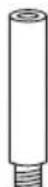
*
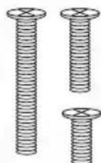
*
3 tornillos
a la contra manga
Fig. 1.
- CONSTRUCCIÓN
text_image
40-45 mm 25 mmFig. 4.
Atención!
text_image
Diagram of a door lock assembly with labeled parts A, B, and C, showing internal components and directional arrows indicating movement.
natural_image
Technical line drawing of a door handle assembly with no visible text or symbolsFig. 6.
text_image
Diagram of a handheld device with labeled parts and internal components, showing a hand holding a remote and a close-up view of the interior.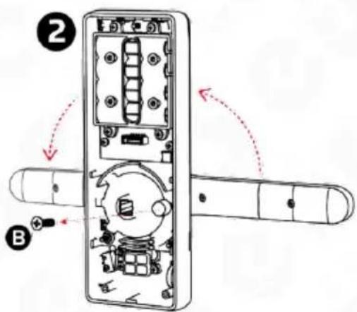
text_image
Diagram of a door handle with labeled parts and directional arrows indicating movement or assembly.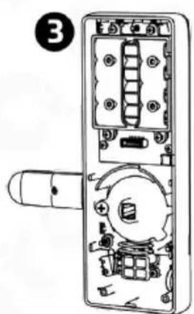
natural_image
Exploded view diagram of a door handle assembly (no text or labels)Fig. 7
text_image
Technical diagram showing hand valve assembly and display panel with battery status indicatorsFig. 9
Atención!
natural_image
Line drawing of a rectangular door with a circular vent and side lock (no text or symbols)Fig. 10.
text_image
Technical diagram of a door lock with labeled components and an inset showing cable connection detailFig. 13
natural_image
Line drawing of a door lock assembly with handle, door, and wall-mounted lock (no text or symbols)Fig. 14
natural_image
Line drawing of a door handle with lever and lock (no text or symbols)Fig. 15
natural_image
Simple line drawing of a door handle with a scroll wheel (no text or symbols)natural_image
Two identical black rectangular electronic components with white plastic outlines and mounting holes (no text or symbols)natural_image
Empty white rectangle with black border (no text or symbols)Instruction

natural_image
Simple line drawing of a rectangular device with two circular holes and a vertical dashed line labeled 'X' (no text or symbols on the device itself)modèle assemblée
*
natural_image
Illustration of four different screw-like rods arranged vertically (no text or symbols)text_image
40-45 mm 25 mmFig. 4.
Attention!
text_image
Diagram of a door switch mechanism with labeled parts A, B, and C, showing internal components and directional arrows.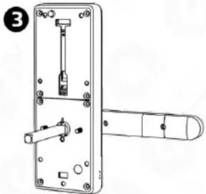
natural_image
Technical line drawing of a door handle assembly with no visible text or symbolsFig. 6.
5.1.2 MISE EN ORIENTATION - DOS DU SIGNAL
text_image
Diagram of a handheld device with labeled parts and internal components, showing a hand holding a remote and a sensor-like device.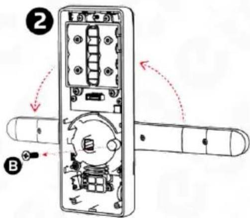
text_image
Diagram of a door handle with labeled parts and directional arrows indicating movement or assembly.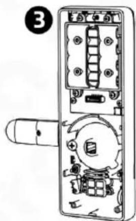
text_image
③Fig.7.
5.2. INSTALLATION DE LA GOUPILLE DANS LA POIGNÉE ÉLECTRONIQUE
natural_image
Technical line drawing of a door lock and smartphone door with a screwdriver, showing internal components without any text or symbols.Fig. 9.
Attention!
natural_image
Line drawing of a rectangular door with a circular opening and side lock (no text or symbols)Fig. 10.
text_image
Technical diagram of a door lock with labeled components and an inset showing cable connection detailFig. 13
natural_image
Line drawing of a door lock assembly with handle, door, and wall-mounted lock (no text or symbols)Fig. 14
natural_image
Line drawing of a door handle with lever and lock (no text or symbols)Fig. 15
text_image
Diagram of a door switch mechanism with labeled parts A, B, and C, showing internal components and directional arrows.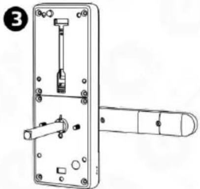
natural_image
Technical line drawing of a door handle assembly with no visible text or symbolsFig. 6.
text_image
Diagram of a remote control device with labeled parts and internal components, showing a hand holding a remote.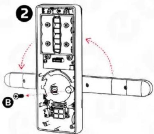
text_image
Diagram of a door panel with labeled parts and directional arrows indicating movement or assembly.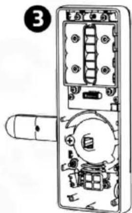
text_image
③Rys. 7
natural_image
Line drawing of a smartphone door handle and its internal control panel with switch, showing no text or symbolsFig. 9.
Attenzione!
natural_image
Line drawing of a rectangular door with a circular opening and side lock (no text or symbols)Fig. 10.
text_image
Technical diagram of a door lock with labeled components and an inset showing cable connection detailFig. 13
natural_image
Line drawing of a door lock assembly with handle, door, and wall-mounted lock (no text or symbols)Rys. 14
natural_image
Line drawing of a door handle with lever and lock (no text or symbols)Fig. 15
Eura-Tech Sp. z o.o. hereby declares that the radio device type - ELH-01H4 electronic door handle with access control - complies with the Directive 2014/53/EU.
Find the full text of the EU declaration at:
www.eura-tech.eu
Eura-Tech Sp. z o.o. reserves the right to change technical parameters and modify the operating manual without notice. It would also
like to inform that the most recent version of the operating manual is available on the
www.eura-tech.eu website,
on the sub-page dedicated to the specific product.
The EU Declaration of Conformity can be found at
http://www.eura-tech.eu
Eura-Tech Sp. z o.o. reserves the right to change technical parameters and modify the operating manual without notice. It would also
like to inform that the most recent version of the operating manual is available on the
www.eura-tech.eu
website, on the sub-page dedicated to the specific product.
The EU Declaration of Conformity can be found at
http://www.eura-tech.eu