ES Reservoir 2U - Computer cooling Alphacool - Free user manual and instructions
Find the device manual for free ES Reservoir 2U Alphacool in PDF.


User questions about ES Reservoir 2U Alphacool
0 question about this device. Answer the ones you know or ask your own.
Ask a new question about this device
Download the instructions for your Computer cooling in PDF format for free! Find your manual ES Reservoir 2U - Alphacool and take your electronic device back in hand. On this page are published all the documents necessary for the use of your device. ES Reservoir 2U by Alphacool.
USER MANUAL ES Reservoir 2U Alphacool
natural_image
3D rendering of a black plastic electrical contactor with visible wiring (no text or symbols)CCOOL
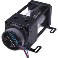
AGB Alphacool ES Reservoir 2U - DDC Version
DEUTSCH ....I
SAFETY INSTRUCTIONS....8
MOUNTING MATERIAL....9
TECHNICAL DETAILS 10
ASSEMBLING ...... I
MOUNTING THE RESERVOIR....14
AGB Alphacool ES Reservoir IU - DDC Version
natural_image
3D rendering of a black electronic component with pins and a green cable, no visible text or symbolsPUMPE ANSCHLIESSEN
natural_image
3D rendering of a black electronic component with ventilation slots and a close-up view showing internal components (no text or symbols)natural_image
3D cutaway view of a black industrial air vent assembly with visible wiring and mounting holes (no text or symbols)natural_image
3D cutaway view of an electrical component with screw fasteners and a color-coded cable (no text or symbols)natural_image
Four black plastic electronic components with visible wiring and connectors, shown from different angles (no text or symbols)MONTAGE OHNE RADIATOR
natural_image
3D rendering of a mechanical assembly with transparent tubes and black connectors (no text or symbols visible)natural_image
Two views of an electrical enclosure with cooling fans and wiring, shown from different angles (no text or symbols visible)IN BETRIEB NEHMEN
natural_image
3D rendering of a blue funnel pouring liquid into a black mechanical component with multicolored wires (no text or symbols visible)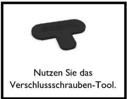
- Not suitable for children under 6 years. (contains small parts which could be swallowed).
- Do not run any cooling components without ensuring that cooling liquid is flowing through the cooling system. Coolers operated without coolant can become very hot. Caution: Burn Hazard!
- Coolers that have no coolant flowing through them can destroy the computer hardware. When switching on the hardware, always make sure that the pump is working.
- Please note when tightening the connectors or fittings, no tools such as screwdrivers, pliers, or wrenches should be used. All plastic products or metal threaded connections, which are linked with plastic parts, are easily over-loaded with tools. Cracking or other damages incurred in this way, as well as damage from leaking coolant, are not covered under the warranty!
- Use only connectors with a sealing o-ring. When using a sealing ring a firm tightening with the hand is enough. Your instruction manual will clearly refer to the use of tools in exceptional cases.
- If you have not done so yet, please check your hardware and cooling system (tightness, pump function and fans). This will minimize time spent searching for possible problems. ALPHACOOL INTERNATIONAL GMBH accepts no liability on the warranty of the manufacturer of the electronic components. The assembly of the cooling system takes place at your own risk.
- The screws should not be tightened too firmly. If you tighten the screws excessively, the knurled nuts can loosen and the cooler's uniform pressure is no longer guaranteed.
- Fasten the connections of your choice to the cooler. Do not use tools such as wrenches for fastening the connections. Connectors with 8mm long threads may stop the flow.
- We recommend a tightness test before assembling/installing the cooler. The water pressure in the water cooling loop can be at a maximum of 0.8 bar. DO NOT use tools on the connectors.
- Ensure that the cooler is touching all components to be cooled through thermal grease and thermal pads.
- Only use distilled water or ALPHACOOL CAPE KELVIN CATCHER in your cooling circuit. Damage caused by unsuitable coolant is not covered by the warranty!
Specified normal operation
All ALPHACOOL INTERNATIONAL GMBH cooling components are constructed and licensed for ALPHACOOL INTERNATIONAL GMBH computer construction parts. The warranty expires in case of misuse.
Warranty
- Data, designs, illustrations, technical data, weight, measurement and specifications, contained in folders, catalogues, circulars, announcements or price lists, have a purely informative character. We do not undertake warranty for the correctness of these data. As to the kind and the range of delivery, the data contained in the order and confirmation of order alone are decisive.
- If there is a lack of warrantor, you are entitled, on the basis of the legal regulations to require subsequent delivery, to withdraw from the contract or reduce the purchase price. If you are a consumer, the limitation period of warranty claims for the supplied commodity amounts to two years starting from receipt of goods (§ 13 BGB). If you are an entrepreneur, in accordance with legal conditions the limitation period amounts to only one year (§ 14 BGB).
- The warranty claim is valid only in combination with the original invoice, the sales slip or an ALPHACOOL confirmation on warranty claim.
- It is ALPHACOOL INTERNATIONAL GMBHs own discretionary authority to replace or repair the defective product or defective component. The replaced product or component changes into property of ALPHACOOL INTERNATIONAL GMBH.
- All warranty claims are accomplished by ALPHACOOL INTERNATIONAL GMBH or its authorized dealers. If the repair is carried out by a non-authorized or assigned person, ALPHACOOL INTERNATIONAL GMBH does not take over either costs or liability, unless the repair has been previously agreed upon with ALPHACOOL INTERNATIONAL GMBH.
- All costs resulting from refitting of the products are not taken over by ALPHACOOL INTERNATIONAL GMBH.
- ALPHACOOL INTERNATIONAL GMBHs warranty excludes the following points:
7.1. Regular controls maintenance and repair or the replacement of parts subject to regular wear and tear.
7.2. Improper manipulation or defects caused by Incorrect installation.
7.3. Damages caused by storm, water, fire, overvoltage, acts of God, war, incorrect connection to the net, insufficient or incorrect ventilation or other reasons over which ALPHACOOL INTERNATIONAL GMBH has no influence.
7.4. Damages resulting from transportation or improper packaging.
- Consumer's rights are valid in the respective country; demands made to the salesman, as explained and laid down in the sales contract, will not be covered by this warranty. ALPHACOOL INTERNATIONAL GMBH, its Branch Office and Distributors, are not responsible for direct or indirect damage or losses, as far as the
compelling legal regulations do not oppose it.
- ALPHACOOL INTERNATIONAL GMBH does not take over the warranty of the manufacturer of the electronic construction units and components. The assembly of the cooler takes place at your own risk.

Contact an authorized waste management company in your country. A waste removal with the municipal waste (unsorted garbage) or similar mechanisms for the collection of local wastes is not permissible!
MOUNTING MATERIAL
AGB Alphacool ES Reservoir IU - DDC Version
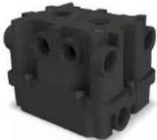 | 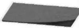 | 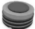 | 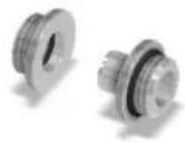 |
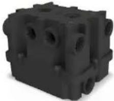
1xreservoir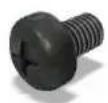 | 1xvelcro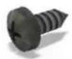 | 10xscrew plugs | 1xdouble nipple |
4xM3x5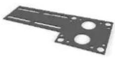 | 4x3,5x9,5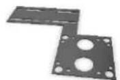 | 4xM4x20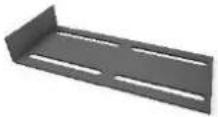 | 1x screw plug tool |
| 2x holder straight | 2x holder angle | 1x hose holder |
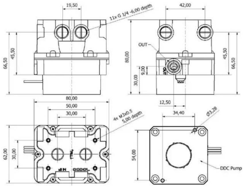
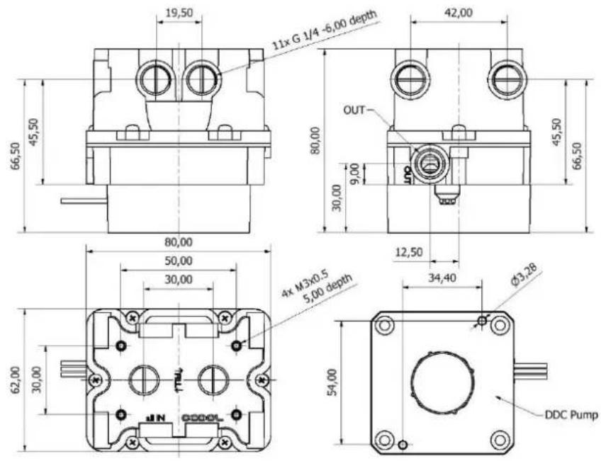
TECHNICAL DETAILS
[Dimensions in mm]
text_image
19,50 11x G 1/4 -6.00 depth 42,00 OUT 80,00 30,00 9,00 45,50 66,50 45,50 66,50 80,00 50,00 30,00 12,50 4x M3x0.5 5.00 depth 34,40 Ø3,28 62,00 30,00 75L JIN DDC Pump 54,00 DDC Pump
text_image
4,50 10,54 40,00 40,00 36,22 42,41 26,57 R2,00 100,26 62,00 Ø20,00 30,00 62,00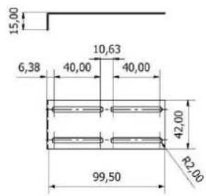
text_image
15,00 6,38 40,00 10,63 40,00 42,00 99,50 R2,00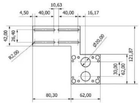
text_image
4,50 10,63 40,00 40,00 16,17 42,00 26,40 R2,00 φ20,00 80,30 62,00 30,00 62,00 121,87ASSEMBLY
PUMP ASSEMBLING
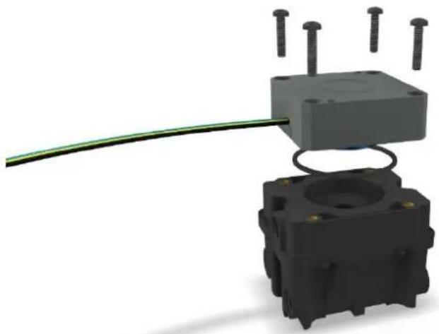
Screw your pump with an O-ring on the expansion tank:
natural_image
3D rendering of a black plastic electrical contactor with wires and pins, no text or symbols visibleCONNECT PUMP
The installation of the DDC pump is described on the supplementary sheet.
MOUNTING ON A RADIATOR
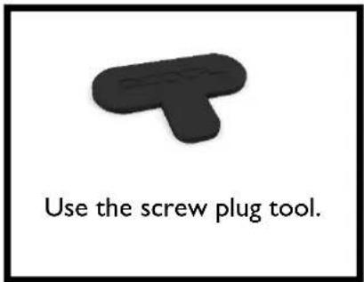
The double nipple consists of two parts. Screw one part into the radiator and one part into the expansion tank. Both parts can now be simply plugged together.
text_image
Use the screw plug tool.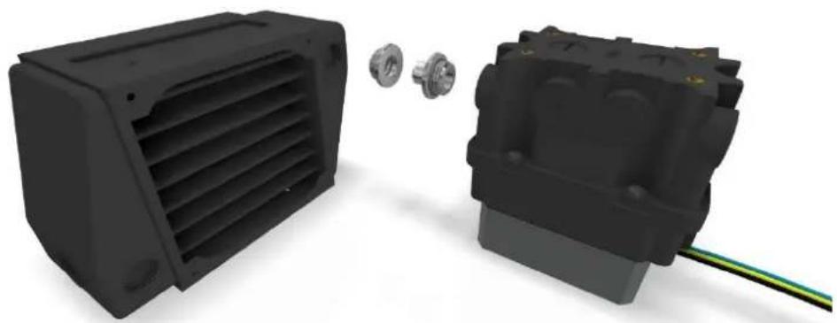
natural_image
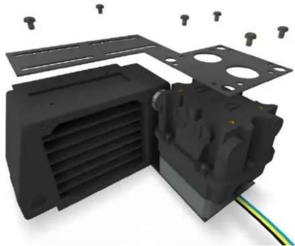
3D rendering of a black electronic component with ventilation slots and a close-up view showing internal components (no text or symbols)Now screw the retaining plate with the M3x5 screws onto the radiator and the expansion tank. Both components are now firmly connected to each other.
natural_image
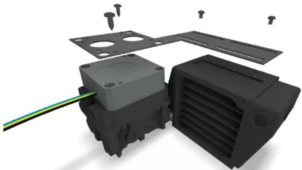
3D cutaway view of a black plastic electronic device showing internal components and mounting holes (no text or symbols)Turn the assembly upside down and screw the second mounting plate on from below. M3x5 screws are used with the radiator. Mount the pump with the 3.5x9.5 screws.
natural_image
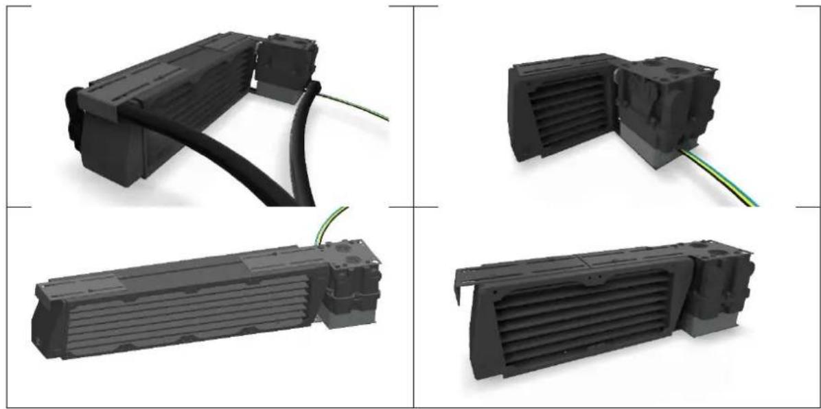
3D rendering of an electrical component with screw fasteners and a colored cable, showing internal structure without any text or symbols.A further mounting variant with the hose holder and the alternative mounting plate.
natural_image
Four black plastic electronic components with visible wiring, shown from different angles (no text or symbols)MOUNTING WITHOUT RADIATOR
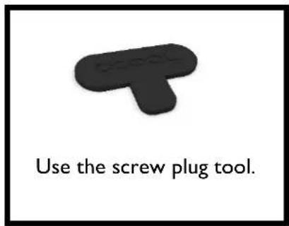
You can also use the reservoir individually without a radiator. Connect the hoses to the reservoir and close the unused inlets with the screw plugs. There are a large number of threads (shown here in transparent form).
text_image
Use the screw plug tool.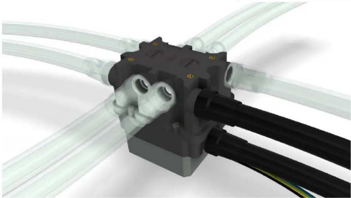
natural_image
3D rendering of a mechanical assembly with transparent tubes and black components (no text or symbols visible)MOUNTING OF THE RESERVOIR
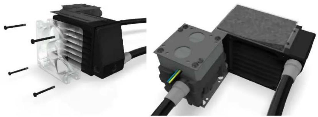
You can also mount the combination of the reservoir and the radiator on a fan.
If it is not possible to screw the reservoir in place, you can use the double-sided velcro tape. It has adhesive strips on both sides to keep the reservoir securely in place.
natural_image
Two views of an electrical heating element with cooling fans and connected cables (no text or symbols visible)INITIAL OPERATION
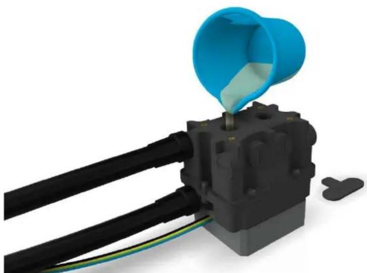
Make sure all openings are closed. Now fill the reservoir through the upper fill port by using a funnel or beaker.
natural_image
3D rendering of a blue funnel pouring liquid into a black electrical component with wires (no text or symbols visible)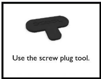
text_image
Use the screw plug tool.We only recommend clear coolants from our own production (CKC or Eiswasser Crystal - no UV!) or pure distilled or osmosis filtered water.
After the pump has been put into operation for the first time, the water level drops because the water must first displace the air in the circuit. To prevent the pump from running dry, the expansion tank must be continuously filled until the water level in the expansion tank does not drop further.
Français
INSTRUCTIONS DE SECURITE
LISEZ LES INSTRUCTIONS DE SECURITE AVANT DE COMMENCER L'INSTALLATION
AGB Alphacool ES Reservoir IU - DDC Version
 |  |  |  |
1x réservoir de dilatation | 1x scratch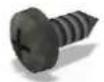 | 10x vis de blocage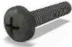 | 1x double mamelon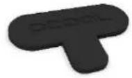 |
4x M3x5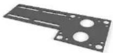 | 4x 3,5x9,5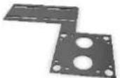 | 4x M4x20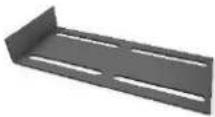 | 1x outil de vissage |
| 2x support droit | 2x angle du support | 1x support de tuyau |
DÉTAILS TECHNIQUES
[dimensions in mm]
text_image
19,50 11x G 1/4 -6.00 depth 42,00 66,50 45,50 80,00 OUT 30,00 9,00 45,50 66,50 80,00 50,00 30,00 12,50 4x M3x0.5 5.00 depth 34,40 Ø3,28 62,00 30,00 54,00 DDC Pump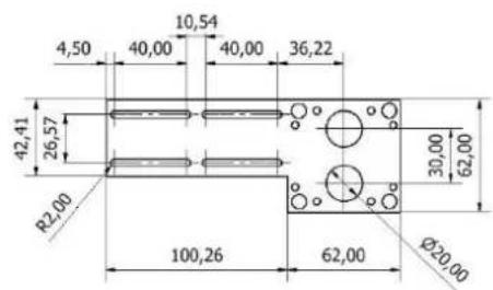
text_image
4,50 10,54 40,00 40,00 36,22 42,41 26,57 R2,00 100,26 62,00 Ø20,00 30,00 62,00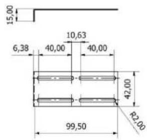
text_image
15,00 6,38 40,00 10,63 40,00 42,00 99,50 R2,00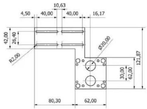
text_image
4,50 10,63 40,00 40,00 16,17 42,00 26,40 R2,00 φ20,00 80,30 62,00 30,00 62,00 121,87MONTAGE
ASSEMBLAGE DE LA POMPE
natural_image
3D rendering of a black electrical component with pins and a green cable, no visible text or symbolsRACCORDER LA POMPE
natural_image
3D rendering of a black electronic component with ventilation slots and a close-up view showing internal components (no text or symbols)natural_image
3D rendering of a black industrial air vent assembly with mounting flanges and wiring (no text or symbols visible)natural_image
3D cutaway view of an electronic device showing internal components and screw fasteners (no text or symbols)natural_image
Four black plastic electronic components with visible wiring, shown from different angles (no text or symbols)MONTAGE SANS RADIATEUR
natural_image
3D rendering of a mechanical assembly with transparent tubes and black components (no text or symbols visible)FIXATION DU VASE D'EXPANSION
natural_image
Two views of an electrical component with cooling fans and wiring, shown from different angles (no text or symbols visible)MIS EN SERVICE
natural_image
3D rendering of a mechanical assembly with blue funnel pouring into a black component, no visible text or symbols