VDV Scout Pro VDV501-814 - Measuring equipment Klein Tools - Free user manual and instructions
Find the device manual for free VDV Scout Pro VDV501-814 Klein Tools in PDF.

| Brand | Klein Tools |
| Model | VDV Scout Pro VDV501-814 (also VDV501-053 and VDV501-068 LT) |
| Product Type | Portable cable tester for voice, data and video |
| Dimensions | 16.3 x 7.1 x 3.6 cm |
| Weight | 256 g (with battery and sensor) |
| Power | 9 V alkaline battery |
| Standby battery life | 4 years |
| Active battery life | 425 hours |
| Cable types tested | Cat-7, Cat-7a, Cat-6a, Cat-6, Cat-5e, Cat-5, Cat-4, Cat-3, coaxial (shielded or unshielded) |
| Supported connectors | RJ11, RJ12, RJ45, F (coaxial) |
| Main functions | Continuity test, cable identification, tone generator, length measurement (LT model) |
| Fault detection | Short circuits, open circuits, reversals, miswires, split pairs |
| Display | Large LCD screen |
| Maximum RJ cable length | Up to 305 m (1000 ft) |
| Length measurement (LT model) | By capacitance, 1 to 2000 ft (610 m), resolution 1 ft |
| Length measurement accuracy (LT) | ±(5% + 1 ft) without constant accuracy |
| Operating temperature | 0 °C to 50 °C |
| Storage temperature | -20 °C to 60 °C |
| Humidity | 10 % to 90 % non-condensing |
| Maintenance | Clean with a damp cloth; no solvents |
| Safety | Do not use on live circuits; max voltage between pins: RJ 36 V DC/55 V AC, F 66 V DC/55 V AC |
| Warranty | 2 years |
Frequently Asked Questions - VDV Scout Pro VDV501-814 Klein Tools
User questions about VDV Scout Pro VDV501-814 Klein Tools
0 question about this device. Answer the ones you know or ask your own.
Ask a new question about this device
Download the instructions for your Measuring equipment in PDF format for free! Find your manual VDV Scout Pro VDV501-814 - Klein Tools and take your electronic device back in hand. On this page are published all the documents necessary for the use of your device. VDV Scout Pro VDV501-814 by Klein Tools.
USER MANUAL VDV Scout Pro VDV501-814 Klein Tools
text_image
Voice Data Video Tone Pass X-over Rev ▼ Fail Short Split Open Shielded Voltage!ID 1 2 3 4 5 6 7 8VUV501-053

text_image
Voice Data Video Tone Pass X-over Rev ▼ Fail Short Split Open Shielded Voltage!ID 1 2 3 4 5 6 7 8For Professionals...Since 1857®
Español pg. 12
Français pg. 23
KLEIN TOOLS®
www.kleintools.com
VDV501-068
VDV Scout™ Pro & VDV Scout™ Pro LT
Instruction Manual
GENERAL SPECIFICATIONS
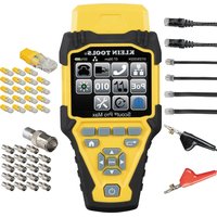
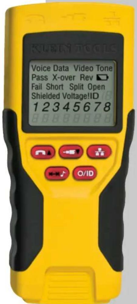
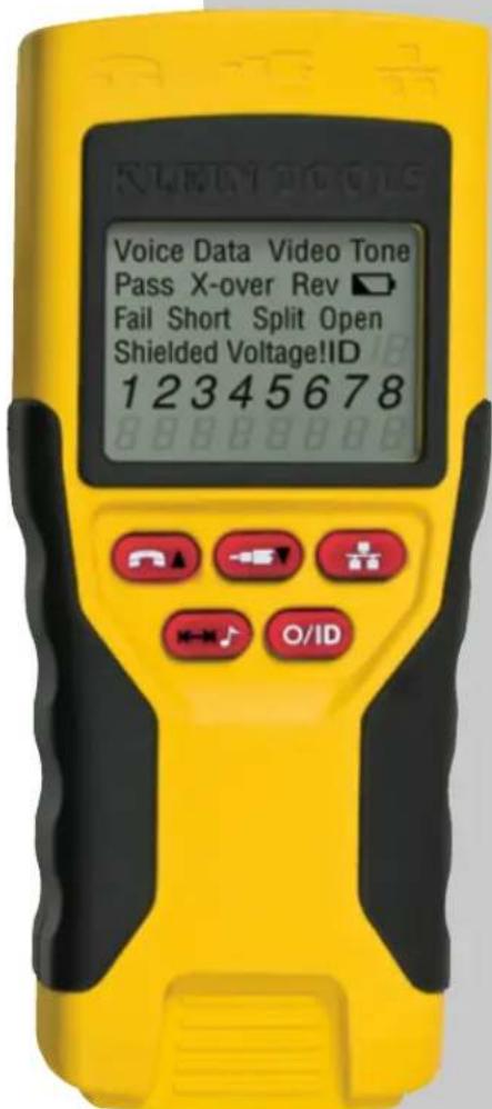
The Klein Tools VDV Scout™ Pro is a portable voice-data-video cable tester. It tests and troubleshoots RJ11, RJ12, RJ45, and F-connector terminated cables and provides built-in tone generation for cable tracing. The VDV Scout™ Pro LT combines these features with length measurement.
Sections and lines marked [LT] and in RED are relevant only to VDV501-068 VDV Scout™ Pro LT.
• Dimensions: 6.4" x 2.8" x 1.4" (16.3 x 7.1 x 3.6 cm)
• Weight: 3.0 oz. (256 grams) with battery and remote
• Operating Temperature: 0°C / 32°F to 50°C / 122°F
• Storage Temperature: -20°C / -4°F to 60°C / 140°F
• Humidity: 10% to 90%, non-condensing
• Maximum Voltage between any two connector pins without damage:
• RJ Jack: 56V DC or 55V AC
- -Connector: 66V DC or 55V AC
- Battery Life: 9V alkaline battery typical
- standby: 4 years
• Active: 425 hours
- Cable Types: Shielded or Unshielded: Cat-7, Cat-7a, Cat-6a, Cat6, Cat-5e, Cat-5, Cat-4, Cat-3, Coax
• Maximum RJ Cable Length: 0 to 1000 feet (305 meters)
- Minimum Cable Length for Split Pair Detection
1.5 feet (0.5 meters)
• Maximum Coax Cable Length: 100 ohms maximum DC resistance, center conductor plus shield
• [LT] Length Measurement Method: Capacitance
• [LT] Resolution: 1 ft (0.5 m)
- [LT] Length Measurement Range: 1 to 2000 feet (610m) with 15pF/ft length constant (or 30nF total capacitance)
- [LT] Length Accuracy (Without Length Constant Accuracy): ±5%+1ft) or ±5%+0.5m)
- [LT] Length Constant Range: 10pF/ft to 40pF/ft 33pF/m to 132pF/m)
A WARNINGS
To ensure safe operation and service of the tester, follow these instructions. Failure to observe these warnings can result in severe injury or death.
- The VDV Scout™ Pro is designed for use on unenergized cabling systems. Connecting the VDV Scout™ Pro to live AC power may damage it and pose a safety hazard for the user.
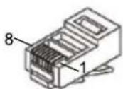
- Poorly terminated RJ plugs have the potential to damage the jacks on the VDV Scout™ Pro. Visually inspect an RJ plug before inserting it into the tester. The contacts should always be recessed into the plastic housing of the plug. Plugging 6-position plugs into the 8-position jack on the tester has the potential to damage the outer-most contacts of the jack unless the plug is specifically designed for that purpose

WARNINGS:
Always wear approved eye protection.

WARNINGS:
Do NOT use on energized circuits.
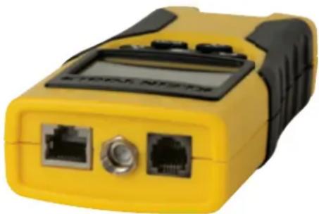
PORTS OVERVIEW
Main Body (left to right)
HJ45 Port: data cable, ethernet cable, 8-wire cable, 4 twisted pair cable, Cat5e, Cat6, Cat6a, Cat7.
F-Connector Port: video cable. coaxial cable. RG6 cable. RG59 cable.
RJ11/12 Port: phone cable, POTS (plain old telephone service) cable, 4-wire cable, 6-wire cable, 2 twisted pair cable, 3 twisted pair cable, Cat3.
natural_image
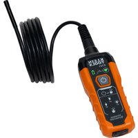
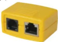
Yellow and black handheld device with two ports and a digital display (no visible text or symbols)Self-Storing Remote (left to right) RJ11/12 Port
RJ45 Port
Use this remote to test for continuity
vDV Scout ^[b] Pro: This remote does not have an associated ID number
natural_image
Yellow rectangular device with two black Ethernet ports, no visible text or symbolsVDV Scout™ Pro LT: This remote has ID number 1.
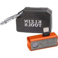
ID Remotes: (included in kit, or sold separately)
LANMap Remote (left): RJ45 connector.
CoaxMap Remote (right): F-connector.
Use these remotes to do cable dentifi cation mapping
LANMap remotes cannot be used to determine continuity.
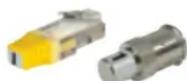
Connectors:
Barrel Connector:
Female-to-female F-connector.

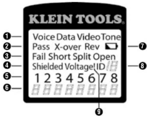
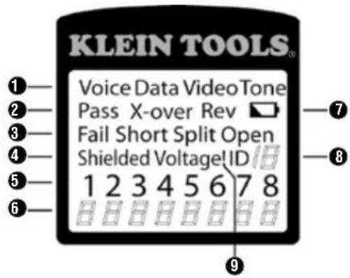
DISPLAY
text_image
KLEIN TOOLS® Voice Data Video Tone Pass X-over Rev ▼ Fail Short Split Open Shielded Voltage ID 1 2 3 4 5 6 7 8 HHHHHHHH ①— ②— ③— ④— ⑤— ⑥— ⑦— ⑧— ⑨—-
Mode: The top line of the display shows the cable type test mode or tone generation mode.
-
Pass/Special Cables: "Pass" will be on if the cable is a properly wired 4-pair T568A/B data cable, a 3-pair one-to-one wired voice cable or a video cable with no faults. In addition, the "X-over" illuminates if a properly wired cross-over (uplink) cable is recognized, or the "Rev" illuminates if the cable is a properly wired reverse-pinned voice cable. The wire map will snow actual pin connections.
-
Cable Faults: The "Fail" icon will be on only if the cable is not wired to one of the cabling standards. An open or short error takes precedence over miswires and the appropriate icon(s) illuminates. The "Split" icon illuminates if the designated pairs are not twisted together in the cable, an AC signal fault.
-
Shield: "Shielded" illuminates when a shielded data cable is properly connected at both ends. It will be flashing if there is a short to a wire in the cable along with that pin number and the "Short" indicator
-
Tester-End Wire Map: The top line displays the pins on the tester end in order. These pins are mapped to the pins on the remote-end shown directly below them on the LCD.
-
Remote-End Wire Map: The bottom line displays the corresponding pin on the remote-end. Dash lines on the remote line indicate shorted pins. No pin numbers displayed on the remote line are open pairs. 'U' indicates an unknown continuity, usually the equivalent of 10kΩ to 100kΩ of DC resistance.
-
Battery Low: The battery low symbol illuminates when the battery is nearing depletion. The symbol will begin to flash when the battery needs to be replaced. Results may be unreliable at this point.
-
Location ID: In the video or the ID modes, the "ID" icon will be on with the number of the remote ID displayed or an error message of "Open" or "Short". In continuous cable test mode, three segments will light up in turn to show when the tester is running subsequent tests
-
Voltage Detected Warning: If voltage is detected on any of the tester connectors, the "Voltage!" icon is turned on. A check for voltage is performed before each test and if found, no test is run. The tester should be disconnected immediately from the source of the voltage
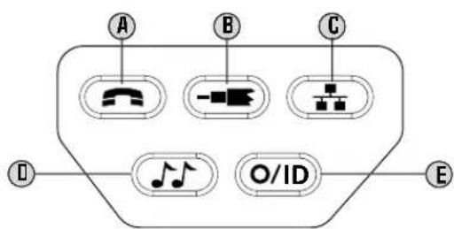
KEYPAC
text_image
A B C D O/ID EA. Voice: Each press of the Voice button causes one test to be run on the 6-position RJ jack and the results displayed. The VDV Scout™ Pro will turn off after 20 seconds automatically. If the button is pressed and held until "LOOP ON" is displayed, tests are run continuously and the display updated until the O/ID button is pressed or after 5 minutes of no change in results. Three hash marks will alternately light up on the display to show the tester is in continuous mode. Continuous mode is useful for trouble-shooting intermittent problems.
B. Video: Pressing the Video button starts the ID test, testing only for the F-connector, because the video continuity test is the same as the ID test. The test loops continuously until the O/ID button is pressed or for 5 minutes after last change in ID status.
C. Data: Each press of the Data button causes one test to be run on the 8-position RJ jack and the results displayed. The VDV Scout™ Pro will turn off after 15 seconds automatically. If the button is pressed and held until "LOOP ON" is displayed, tests are run continuously and the display updated until the O/ID button is pressed or after 5 minutes of no change in results. Three hash marks will alternately light up on the display to show the tester is in continuous mode. Continuous mode is useful for finding intermittent problems
D. Tone: When tone is pressed, the VDV Scout™ Pro begins sending an audio tone for the connector last tested with the pins and cadence previously selected for that connector type. To change the connector type, press a different connector type button. Pressing the same connector type button again will change the pins carrying the tone. Pressing the tone button will cycle through the available tone cadences. To turn the VDV Scout™ Pro off, press the O/ID button. The VDV Scout™ Pro will turn off automatically 60 minutes after the last button press. The tone is compatible only with analog tone tracers such as the Klein Tools VDV500-U6U or VDV526-U54. It will not be audible without the aid of an analog tone probe
E. Off/ID: Pressing O/ID will turn off the VDV Scout™ Pro when it is on in any mode. With the VDV Scout™ Pro off, pressing the O/ID button starts the ID test mode. The ID test mode scans for all possible ID types – voice, video and data. The "ID" icon and a progression of "o" are displayed on the bottom line of the display to indicate scanning is active. If no ID remotes are found, "Open" is displayed. When an ID remote is found, the connector type and the ID number are displayed. If multiple ID remotes are found, the ID or fault is displayed in sequence. The test loops continuously until the O/ID button is pressed or for 5 minutes after last change in ID status.
Note: The RJ jacks share internal connections so only one RJ cable can be connected at a time for accurate cable test results. However, an RJ cable and a coax cable may be connected at the same time. In ID mode, all connectors on the VDV Scout™ Pro may be connected at the same time.
JDV Scout™ Pro Owners: please skip to page 6.
[LT] KEYPAD
![Klein Tools VDV Scout Pro VDV501-814 - [LT] KEYPAD - 1](/content/2026/04/669199/images/424fba3835e1942c075d68a56c6d4872502f46682a1d93fe4b9fc93904f304c1.jpg)
text_image
F G H I ←→↓ O/IDF. Voice/Up Arrow: In Length Measurement mode, press and release to measure length of a cable connected to the RJ11/12 port. Press and release again to change which pair of wires length is being measured on. By default, the VDV Scout™ Pro LT will test for length on the first pair with no faults found In Length Constant Edit mode, this button will increase the length constant by 0.1pF. Hold down to scroll through values quickly
G. Video/Down Arrow: In Length Measurement mode, press and release to measure length of a cable connected to the F-connector port. In Length Constant Edit mode, this button will decrease the length constant by 0.1pF. Hold down to scroll through values quickly
H. Data: In Length Measurement mode, press and release to measure length of a cable connected to the RJ45 port. Press and release again to change which pair of wires length is being measured on. By default, the VDV Scout™ Pro LT will test for length on the first pair with no faults found
I. Tone/Length Measurement: While the tester is on, press and hold for three seconds to enter lone mode (see general keypad section). While the tester is on, press and release to enter Length Measurement mode. In Length Measurement mode, press and release again to briefly show the length constant. Press and hold for three seconds to enter Length Constant Edit mode. Press and release the button one more time to exit Length Constant Edit mode.
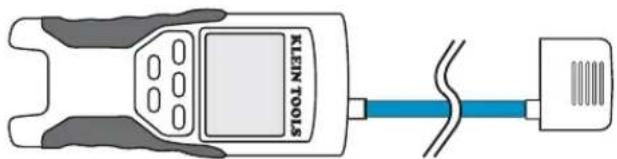
[LT] MEASURING LENGTH - OVERVIEW
The VDV Scout Pro LT uses the capacitive properties of a cable to measure its length. One end of the cable should be connected to the corresponding port on the top of the tester. The other end should be left disconnected or attached to the self-storing remote
The Length Constant sections below discuss the best practices to follow when measuring length in order to achieve the most accurate results
[LT] ABOUT THE LENGTH CONSTANT
The length constant refers to the electrical characteristic of a cable used to characterize length. Every cable has an associated length constant in units of picofarads per foot. Setting the length constant on the tester is important to obtaining an accurate measurement from the VDV Scout™ Pro LT. The default length constants are as follows
- Voice: 17pF/ft
• Data: 15pF/t - Video: 15pF/ft
The length constant can sometimes be provided by the manufacturer or ne cable (see EDITING LENGTH CONSTANT section). You may have to determine the length constant yourself (see DETERMINING LENGTH CONSTANT section). Length constants can range from 10pF/ft to 40pF/ft
Measurement accuracy is dependent on how close the tester can be set to the length constant of the cable being measured and the consistency of the cable along its length
The length constant can vary from cable to cable, even of the same type produced by the same manufacturer. It can also vary over the length of one cable because the length constant is dependent on the physical properties of the cable, which may not be consistent throughout the entire cable. The change in wire pair spacing through the cable can vary the length constant along the length of the cable.
When setting the length constant using a length of cable, the cable should be at least 50 feet long. This will yield a ± 2% uncertainty (1 in 50) of length constant accuracy. A longer cable reduces this uncertainty
[LT] MEASURING LENGTH
![Klein Tools VDV Scout Pro VDV501-814 - [LT] MEASURING LENGTH - 1](/content/2026/04/669199/images/a700b46ba12b406b22153545ded0a4098a5b97b37b6932006fc388a81b8d7fce.jpg)
text_image
KLEIN TOOLS- Connect one end of the cable under test to the RJ45 port (if you are testing an ethernet cable) or RJ12 port (if you are testing a phone cable) or F-connector port (if you are testing a coax cable) located at the top of the main tester body. Leave the other end of the cable unterminated.
- Press the length button ① to enter length mode.
- Press the data button Ⓗ or the phone button Ⓕ or the video button Ⓛ on the keypad to begin the test on the ethernet cable or phone cable or coax cable, respectively
- (Optional) press Ⓗ or Ⓕ repeatedly to select the pair of wires that should be measured. The first pair that is functional is chosen by default.
- Read the length measurement as shown.
Note: A phone or data cable under test can be unterminated (open) or terminated by an RJ45 ID remote. If it is terminated by the self-storing remote, the reading will be 1 or 2 feet greater than the actual measurement. In this case, subtract 1 or 2 feet from the reading to obtain the actual measurement. Coax cable under test must be left unterminated. Coax ID remotes cannot be used
![Klein Tools VDV Scout Pro VDV501-814 - [LT] MEASURING LENGTH - 2](/content/2026/04/669199/images/d095db84aad0fab55788dd17c1ba11906435edf61480fda2b6f1902a86ad2990.jpg)
text_image
KLEIN TOOLS Data Cable Type Test Running Continuously Length Measurement Mode Measured Length = 45 feet[LT] DISPLAYING LENGTH CONSTANT
- Assure the tester is off
and the screen is blank.
- Press the length button
① to enter length mode.
- Press the length button
① again. The length constant will be displayed on the screen for three seconds as shown below.
![Klein Tools VDV Scout Pro VDV501-814 - [LT] DISPLAYING LENGTH CONSTANT - 1](/content/2026/04/669199/images/41cbeb2428b1f9001fb98a685b460a24014a5a3e47a1bba4844ae002c9a711e3.jpg)
text_image
KLEIN TOOLS Data Length Constant = 15.0pF/ft 15.0 PFr Length Constant Display Mode[LT] LENGTH CONSTANT EDIT MODE
Follow these instructions to set the length constant based on a known value (for example, as given by the cable manufacturer). The VDV Scout™ Pro LI stores a separate length constant for each of the three cable types (voice, data, and video)
- Follow the procedure in MEASURING LENGTH section to set up the correct type of cable.
- Press and hold the length button ① for three seconds until EDIT CAP is shown on the screen.
- Press the Up Arrow F and Down Arrow C to increment or decrement the length constant in units of 0.1pF to the desired value. The screen will switch back and forth between the length measurement and the length constant value every two seconds while no buttons are pressed.
- Press the length button ① again to return to length measurement.
![Klein Tools VDV Scout Pro VDV501-814 - [LT] LENGTH CONSTANT EDIT MODE - 1](/content/2026/04/669199/images/a3dced72dbf0f9ccac9310b1b48e52d8b96a7d230b63736709b150b9357ca611.jpg)
text_image
KLEIN TOOLS Data Length Constant = 15.0pF/ft E 15_0 PFr Length Constant Edit Mode[LT] DETERMINING LENGTH CONSTANT
Follow these instructions to set the length constant based on a sample cable or known length. For best accuracy, the sample cable should be 50ft or greater.
- Cut or obtain a length of cable of the same type you would like to measure. Measure the cable using standard methods (pad printing on the cable or a tape measure).
- Follow the procedure in MEASURING LENGTH section to set up the cable to be tested.
- Press and hold the length button ① for three seconds until EDIT CAP is shown on the screen.
- Press the Up Arrow F and Down Arrow C to increment or decrement the length constant in units of 0.1pF. The screen will switch back and forth between the length measurement and the length constant value every two seconds while no buttons are pressed. Press the arrows until the length measurement is the same as the value measured earlier. The length constant can still be changed while the length measurement is being viewed in this mode.
- Press the length button ① again to return to length measurement. You may now measure other unknown lengths of cable
![Klein Tools VDV Scout Pro VDV501-814 - [LT] DETERMINING LENGTH CONSTANT - 1](/content/2026/04/669199/images/31addb1e441e8e26ba6bea2f1bdb4bcd2f2614af980b9a98a210f6e9722ae5cb.jpg)
text_image
KLEIN TOOLS Data Pair of Wires Under Test Measured Length = 86 feet 1 2 E B G F T Length Constant Edit Mode[LT] CHANGING UNIT OF MEASUREMENT
- Assure the tester is off and the screen is blank.
- Press the length button ① to enter length mode.
- Press the phone button F and video button C at the same time. The screen will show "METERS" or "FEET" momentarily, then show the length measurement in the unit selected.
Note: Feet unit readings have no decimal place and are displayed as '0 Ft'. Meters unit readings have one decimal place and are displayed "0_0" for 0.0 meters. Length constants are displayed in pF/ft or pF/m depending on the selected unit measurement mode.
TESTING CONTINUITY - OVERVIEW
When testing for continuity of a cable, you are checking that all conductors within a cable are connected properly from one end to the other.
Usually, faults occur when terminations on each side are not connected (an "open"), or when adjacent conductors are accidentally connected (a "short").
TESTING CONTINUITY - TERMINATED RJ45/RJ12 CABLE
text_image
KLEIN TOOLS8-wire ethernet cables can have an additional set of errors. A miswire simply means that the pin on one side of the cable is not connected to the identical pin on the other side of the cable (for example, pin 2 on one side is connected to pin 6 on the other side). Certain pairs of conductors are required to be twisted together from endpoint to endpoint. These errors are called split pairs, and can be present in cables that don't have any miswires.
Testing continuity is not the same as testing bandwidth. More sophisticated testers exist for verifying the amount of data that can pass through a cable.
- Connect one end of the cable under test to the RJ45 port (if you are testing an ethernet cable) or RJ12 port (if you are testing a phone cable) located at the top of the main tester body
- Detach self-storing remote from the tester body. (ID remotes cannot be used.)
- Connect the other end of the cable to the corresponding port on the self-storing remote.
- Press the data button C or the phone button A on the keypad to begin the test on the ethernet cable or phone cable, respectively
- Interpret the results of the test using the Wiring and Display Examples section
TESTING CONTINUITY - INSTALLED RJ45/RJ12 CABLE
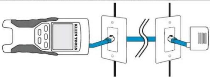
text_image
KLEIN TOOLS- Detach self-storing remote from the tester body
- Attach a known good patch cable from the wall port at one end of the cable under test to the RJ45 port (for ethernet cable) or RJ12 port (for phone cable) on the self-storing remote.
- Attach another known good patch cable from the wall port at the other end of the same cable under test to the corresponding port located on the top of the main tester body.
- Press the data button Ⓐ or the phone button Ⓐ on the keypad to begin the test on the ethernet cable or phone cable, respectively.
- Interpret the results of the test using the Wiring and Display Examples section
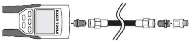
TESTING CONTINUITY - TERMINATED COAX CABLE
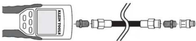
text_image
LENTS TOOLS- Attach barrel connector to the open coax port on the top of the main tester body.
- Connect one end of the cable to the barrel connector at the top of the main tester body
- Attach a second barrel connector (not included) to the other end of the cable under test.
- Connect a numbered CoaxMap remote onto the second barrel connector.
- Press the video button ⑧ on the keypad to begin the test on the coax cable.
b. Interpret the results of the test using the Wiring and Display Examples section
TESTING CONTINUITY - INSTALLED COAX CABLE
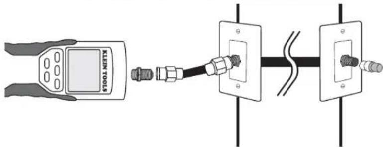
text_image
KEEN TOOL KEEN TOOL- Attach barrel connector to the open coax port on the top of the main tester body.
- Connect a known working patch cable to the barrel connector at the top of the main tester body.
- Connect the other end of the patch cable to the wall port of the cable under test.
- Connect a numbered CoaxMap remote onto the wall port on the other end of the cable under test.
- Press the video button Ⓔ on the keypad to begin the test on the coax cable.
- Interpret the results of the test using the Wiring and Display Examples section.
CABLE IDENTIFICATION - OVERVIEW
It is often necessary to identify cables that branch out from the wiring closet in a star-topology network configuration.
The VDV Scout™ Pro can assist in this in two ways.
The most convenient way to identify installed cables is by using ID remotes (5 of each LAN and coax are included in the VDV501-809 kit, and 19 are included in the VDV526-055 LANMap Kit and the VDV512-056 CoaxMap Kit, sold separately). Using ID remotes, you can trace up to 19 satellite locations with one trip to the wiring closet or router. Identification with ID remotes is done digitally, and does not rely on any manual tracing.
The second way to identify cables is using the VDV Scout™ Pro's built-in analog tone generator. The tester will place a low-frequency voltage on the cable. By using an analog tone probe (Klein Tools VDV526-054, VDV500-060, or most other manufacturer's analog tone probes, sold separately), a cable can be identified by the tone it is carrying. This technique only allows one cable to be traced per tone generator, but has additional benefits like the ability to trace a cable manually behind certain wall materials, or trace unterminated cables of non-standard types.
It is important to note that the .ANMap remotes cannot be used to verify continuity. Only the self-storing remote that snaps into the bottom of the tester can be used to test continuity of data or phone cables.
However, CoaxMap remotes are used to both verify continuity and identify coax cables. Any numbered CoaxMap remote can be used to test continuity. There is no coax termination built into the self-storing remote.
CABLE IDENTIFICATION - INSTALLED RJ45 CABLE
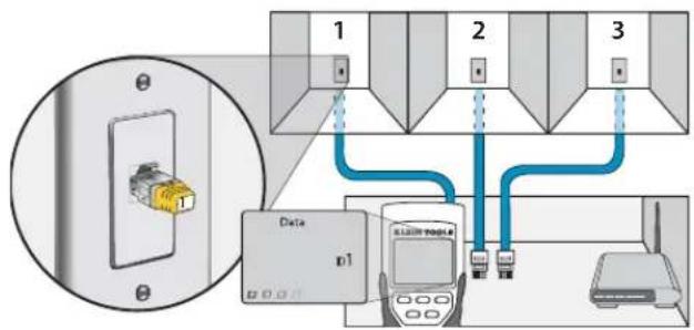
text_image
1 2 3 Data p1 SLAW Mobile w- Insert a numbered LANMap remote into the RJ45 port of each room that needs to be identified. Mark down pairs of numbers and room names for later
- Take the VDV Scout ™ Prn to the wiring closet or router (the source of the internet connection).
- Connect an unknown cable to the RJ45 port on the top of the tester
- Press the ID button ☑ on the keypad to begin the ID test on the ethernet cable. The LCD will read "Data ID#" where "#" is the ID number of the LANMap remote connected to the other side of the cable. Compare this number to the number/room pair list you made in step 1 and mark the cable with a piece of labeled tape.
- Repeat steps 3 and 4 for each unknown cable until all have been labeled. You can use these labels to determine which rooms should be connected to the router, or to troubleshoot intermittent connections in the future.
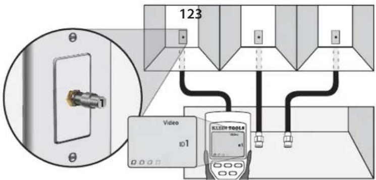
CABLE IDENTIFICATION - INSTALLED COAX CABLE
text_image
123 Video ID1 KLEEN TOOLS- Insert a numbered CoaxMap remote numbers and room names for later into the F-connector port of each room that needs to be identified. Mark down pairs of
- Take the VDV Scout TM Pro to the wiring closet or cable splitter (the source of the cable connection).
- Connect an unknown cable to the video port on the top of the tester.
- Press the ID button Ⓔ on the keypad to begin the ID test on the ethernet cable. The LCD will read "Video ID#" where "#" is the ID number of the CoaxMap remote connected to the other side of the cable. Compare this number to the number/room pair list you made in step 1 and mark the cable with a piece of labeled tape
- Repeat steps 3 and 4 for each unknown cable until all have been labeled. You can use these labels to determine which rooms should be connected to the cable splitter, or to troubleshoot intermittent connections in the future
Note: Ethernet and coax cable can be identified simultaneously. When both cables are connected at the same time and the ID button is pressed, "Video ID#" and "Data ID#" will alternate on the LCD screen.
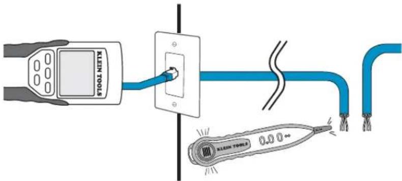
CABLE IDENTIFICATION - RJ45/RJ12 TONE TRACING
text_image
KLEIN TOOLS 0.0 0.0- Connect a known working patch cable to the RJ45 port (if you are tracing an ethernet cable) or RJ12 port (if you are tracing a phone cable) located at the top of the main tester body
- Connect the other end of the patch cable to the wall port at the satellite location of the cable under test (not at the wiring closet).
- Press the tone button ① on the keypad to initialize the tone generation. Press it repeatedly to change the tone cadence from a steady low or high tone to a warbling slow or fast tone
- Press the data button ① or the phone button ② repeatedly to select the output port of the tone and the pins the tone will be placed on
- Take the analog tone probe to the wiring closet or router (the source of the internet connection). Activate the tone probe (see tone probe instruction manual for details)
- Place the tone probe near each cable entering the wiring closet. The tone will be loudest at the cable that the VDV Scout™ Pro is connected to. Mark the cable with a label
- Repeat steps 2-6 for each room that has installed cable.
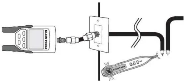
CABLE IDENTIFICATION - COAX TRACING
text_image
KLEIN TOOLS 0.3Ω- Attach barrel connector to the open coax port on the top of the main tester body.
- Connect a known working patch cable to the barrel connector at the top of the main tester body.
- Connect the other end of the patch cable to the wall port at the satellite location of the cable under test (not at the wiring closet)
- Press the tone button ☐ on the keypad to initialize the tone generation. Press it repeatedly to change the tone cadence from a steady low or high tone to a warbling slow or fast tone.
- Press the video button Ⓔ to place the tone on the coax output port
- Take the analog tone probe to the wiring closet or cable splitter (the source of the cable connection). Activate the tone probe (see tone probe instruction manual for details).
- Place the tone probe near each cable entering the wiring closet. The tone will be loudest at the cable that the VDV Scoul™ Pro is connected to. Mark the cable with a label
- Repeat steps 2-7 for each room that has installed cable
FREQUENTLY ASKED QUESTIONS
- Does the VDV Scout™ Pro measure cable length?
The VDV Scout™ Pro does not measure cable length. The VDV Scout™ Pro LT does measure cable length
- Does the VDV Scout™ Pro LT use Time Domain Refl ectometry (TDR)?
The VDV Scout™ Pro LT does not use TDR to measure cable length. The capacitive properties of a cable are used to determine the cable length.
- Does the VDV Scout TM Pro test the bandwidth of the cable?
The VDV Scout™ Pro only performs continuity related tests and split pair testing.
- The screen is flashing "3" and "6" with "U" underneath them when I try to test the continuity of an ethernet cable. What is wrong?
The VDV Scout™ Pro only tests continuity on cables terminated with the self-storing remote that snaps into the bottom of the tester. It cannot test continuity on cables terminated with the small "ID" remotes
- The screen is flashing "For ID Test Only" with an ID number showing when I try to test the continuity of an ethernet cable. What is wrong?
The VDV Scour™ Pro only tests continuity on cables terminated with the self-storing remote that snaps into the bottom of the tester. It cannot test continuity on cables terminated with the small "ID" remotes
- When I am testing continuity of an ethernet or phone cable, there are 3 vertical hash marks moving across the right side of the screen. What does this mean?
In continuity test mode, the vertical hash marks indicate that the tester is in loop mode. Tests are run continuously on the cable in this mode, and the tester will turn off automatically if the same test result is returned for 5 minutes. To enable or disable loop mode, hold the data button C or the phone button A for about 3 seconds. In coax continuity mode, loop mode is always active. In tone generation mode, the vertical hash marks indicate the tone is active
- How do I know which end of a cable is bad?
It is not possible to directly determine which end of the cable is bad with the VDV Scout™ Pro. Assuming that the cable is not damaged somewhere in its length (i.e. it's a brand new cable), you can sometimes determine which end to redo based on the diagnostic message. For instance, if the cable says there is this miswire:
Then you can usually determine which end just by looking closely again at your terminations through the clear plug. For opens and shorts, it is not as easy to determine whether a pin is making contact with the wire just from observation. It could also be bad at both ends
- Why don't I hear anything when the tester is in the tone mode?
In order to hear the tone, an analog tone probe must be used to pick up the signal emitted from the VDV Scout™ Pro. (Try Klein Tools VDV500-060 or VDV526-054)
WIRING AND DISPLAY EXAMPLES
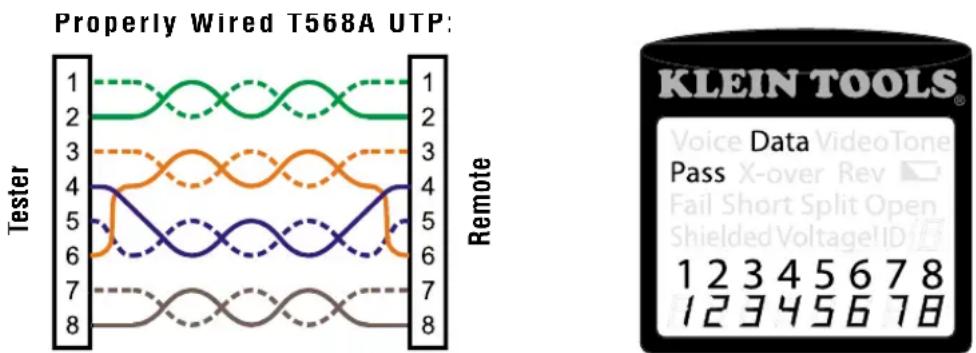
Properly Wired T568A UTP
1568B is electrically identical to 1568A, but swaps the green and orange pairs. Either standard will work as long as the same standard is used at both ends of a run or patch cable. Mixing "A" and "B" creates a cross-over cable.
WIRING AND DISPLAY EXAMPLES
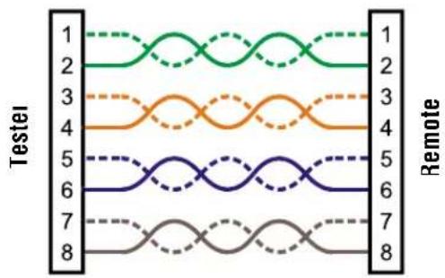
T568A Cable with Split Pairs:

text_image
KLEIN TOOLS® Data Split 1 2 3 4 5 6 7 8 1 2 3 4 5 6 7 8T568A Cable with Split Pairs: A common error in building a cable is to put all the pairs in pin sequence 1-2, 3-4, 5-6 and 7-8. This will produce the correct continuity, but the pairs are designated to be on pins 3-6 and 4-5 in the middle of the connector for compatibility with phone wiring. This wiring error is only detected by the split pair test since the designated pairs are not twisted together
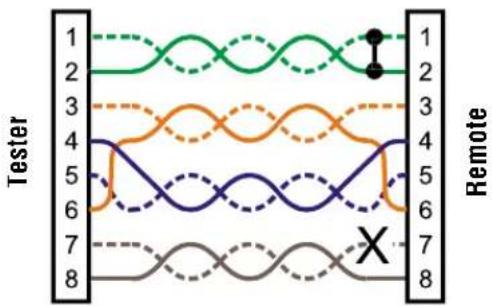
T568A Cable with a Short and Open:
line
| Tester | Remote | | ------ | ------ | | 1 | 1 | | 2 | 2 | | 3 | 3 | | 4 | 4 | | 5 | 5 | | 6 | 6 | | 7 | 7 | | 8 | 8 |
text_image
KLEIN TOOLS® Data Voice Video Tone Pass X-over Rev Fail Split Open Short Split Open 1 2 3 4 5 6 7 8 3 4 5 6T568A Cable with a Short and an Open The 1-2 pair pins are shorted together and the 7-8 pair is open. The pins with the errors are flashing. Dash lines (-) on the bottom (remote) display line indicate the short, while no numbers on the bottom line indicate the open pair
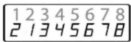
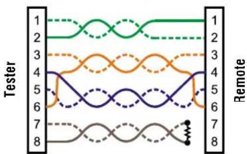
T568A Cable with a Miswire and Unrecognized Continuity:
line
| Test | 1 | 2 | 3 | 4 | 5 | 6 | 7 | 8 | |------|---|---|---|---|---|---|---|---| | Tester | Green Solid | Green Dashed | Orange Solid | Orange Dashed | Blue Solid | Blue Dashed | Gray Solid | Gray Dashed | | Remote | Green Solid | Green Dashed | Orange Solid | Orange Dashed | Blue Solid | Blue Dashed | Gray Solid | Gray Dashed |
text_image
KLEIN TOOLS® Data Voice Video Tone Pass X-over Rev Fail Short Split Open Shielded VoltageID 1 2 3 4 5 6 7 8 2 3 4 5 6 U UT568A Cable with a miswire and unrecognized continuity: 1 and 2 pins on the VDV Scout™ Pro are connected to pins 2 and 1 at the remote-end. The pins with this error are flashing. The "U" for the remote pin number indicates an unrecognizable continuity was detected that is neither a short or open. An ID remote connected to the VDV Scout™ Pro when in cable test mode would also show this error.

Coax Cable Properly Wired:
Coax Cable Properly Wired with ID Remote #1: The #1 ID remote is used to terminate a properly wired coax cable. The video test passes, ID #1 is detected, and the "o's across the bottom of the screen show that the tester is running tests continuously

text_image
KLEIN TOOLS® Voice Data Video Pass X-over Rev Fail Short Split Open Shielded Voltage ID / 1 2 3 4 5 6 7 8WIRING AND DISPLAY EXAMPLES
Coax Cable with an Open:
natural_image
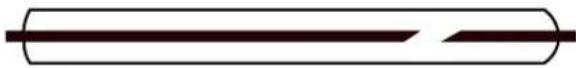
Simple line drawing of a cylindrical object with a horizontal line and a diagonal stripe (no text or symbols)Coax Cable with an Open: There is a break in the cable continuity. A break in the shield or in the center wire can cause an open fault. The cable does not pass and the ID remote number on the other end of the cable cannot be determined.

text_image
KLEIN TOOLS® Voice Data Tone Pass X-over Rev Fail Short Split ShieldedVoltage!ID 1 2 3 4 5 6 7 8Coax Cable with a Short:

natural_image
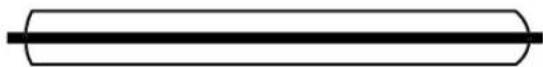
Pure electrical circuit lines without any symbolsCoax Cable with a Short: The center wire of the cable is connected to the shield, creating a short. The cable does not pass and the ID remote number on the other end of the cable cannot be determined.

text_image
KLEIN TOOLS® Voice Data Video Tone Pass X-over Rev □ Fail Split Open ShieldedVoltageID 1 2 3 4 5 6 7 8 □ □ □ □ □BATTERY REPLACEMENT
- Remove single screw in the middle of the back of the VDV Scout™ Pro with a #1 Phillips head screwdriver. Remove battery door
- Disconnect battery cable and recycle exhausted battery
- Acquire a 9 volt alkaline battery (IEC 6LR61, ANSI/NEDA 1640A)
- Connect battery cable to new battery observing polarity and place into battery compartment.
- Replace battery door and screw, taking care not to over-tighten it
WARRANTY
This product is warranted to be free from defects in materials and workmanship for a period of two years from the date of purchase. During this warranty period, Klein Tools has the option to repair, replace or refund the purchase price of any unit which fails to conform to this warranty under normal use and service. This warranty does not cover damage which occurs in shipment or failure which results from alteration, tampering, accident, misuse, abuse, neglect, or improper maintenance. Batteries and damage resulting from failed batteries are not covered by warranty. A purchase receipt or other proof of original purchase date will be required before warranty repairs will be rendered.
Any implied warranties, including but not limited to implied warranties of merchantability and fitness for a particular purpose, are limited to the express warranty. Klein tools shall not be liable for loss or use of the instrument or other incidental or consequential damages, expenses, or economic loss, or for any claim or claims for such damage, expenses or economic loss
Some states or countries laws vary, so the above limitations or exclusions may not apply to you. This warranty gives you specific legal rights, and you may also have other rights which vary from state to state. If your Klein product requires repair or for information on how to exercise your rights under the terms of this warranty, please contact Klein Tools at 1-800-553-4676
CLEANING
Turn instrument off and disconnect any cables. Clean the instrument by using a damp cloth. Do not use abrasive cleaners or solvents.
STORAGE
Remove the batteries when instrument is not in use for a prolonged period of time. Do not expose to high temperatures or humidity. After a period of storage in extreme conditions exceeding the limits mentioned in the Specifications section, allow the instrument to return to normal operating conditions before using it.
DISPOSAL / RECYCLE
Caution: This symbol indicates that equipment and its accessories shall be subject to a separate collection and correct disposal.

CUSTOMER SERVICE
text_image
Voice Data Video Tone Pass X-over Rev ▼ Fail Short Split Open Shielded Voltage!ID 1 2 3 4 5 6 7 8VDV501-053
text_image
Voice Data Video Tone Pass X-over Rev ▼ Fail Short Split Open Shielded Voltage!ID 1 2 3 4 5 6 7 8natural_image
Yellow wireless device with black ports and a digital display (no visible text or symbols)natural_image
Yellow USB flash drive with two Ethernet ports (no text or symbols visible)

Conectores:
Conector cilíndrico: Conector F hembra-hembra
PANTALLA
text_image
KLEIN TOOLS® Voice Data Video Tone Pass X-over Rev Fail Short Split Open Shielded Voltage ID 1 2 3 4 5 6 7 8text_image
F G H I ←→↓ O/IDtext_image
KLEIN TOOLStext_image
KLEIN TOOLStext_image
KLEIN TOOLStext_image
KLEIN TOOLSnatural_image
Diagram showing a handheld device connected to two electrical outlets with connectors (no text or symbols)text_image
Diagram showing connections between a device, network switches, and a router with labeled componentstext_image
KLEIN TOOLS® Data Pass Voice Video Tone X-over Rev Fail Short Split Open Shielded Voltage ID 1 2 3 4 5 6 7 8 12345678text_image
KLEIN TOOLS® Data Voice Video Tone Pass X-over Rev Fail Short Split Open Shielded VoltageID 1 2 3 4 5 6 7 8 2 3 4 5 6 U Unatural_image
Simple horizontal line intersecting a vertical cylinder (no text or symbols)natural_image
Simple line drawing of a cylindrical object with two horizontal lines and a central gap (no text or symbols)text_image
KLEIN TOOLS® Video Pass X-over Rev □ Fail Short Split Open ShieldedVoltageID 1 2 3 4 5 6 7 8natural_image
Pure electrical circuit lines without any symbolsREEMPLAZO DE LA PILA
text_image
Voice Data Video Tone Pass X-over Rev ▼ Fail Short Split Open Shielded Voltage!ID 1 2 3 4 5 6 7 8VDV501-05:
text_image
Voice Data Video Tone Pass X-over Rev ▼ Fail Short Split Open Shielded Voltage!ID 1 2 3 4 5 6 7 8VDV501-068
VDV Scout™ Pro & VDV Scout™ Pro LT
Mode D'emploi
SPÉCIFICATIONS GÉNÉRALES
natural_image
Yellow handheld electronic device with two ports and a black control panel (no visible text or symbols)natural_image
Yellow rectangular device with two black Ethernet ports (no text or symbols visible)VDV Scout™ Pro: Ce capteur a número d'identifi cation 1.
text_image
KLEIN TOOLS® Voice Data Video Tone Pass X-over Rev Fail Short Split Open Shielded Voltage ID 1 2 3 4 5 6 7 8 8text_image
F G H I ←→↓ O/IDtext_image
KLEIN TOOLStext_image
KLEIN TOOLStext_image
KLEIN TOOLSTESTS DE CONTINUITÉ - CÂBLE COAXIAL TERMINÉ