HVCT1 - Measuring equipment Klein Tools - Free user manual and instructions
Find the device manual for free HVCT1 Klein Tools in PDF.

User questions about HVCT1 Klein Tools
0 question about this device. Answer the ones you know or ask your own.
Ask a new question about this device
Download the instructions for your Measuring equipment in PDF format for free! Find your manual HVCT1 - Klein Tools and take your electronic device back in hand. On this page are published all the documents necessary for the use of your device. HVCT1 by Klein Tools.
USER MANUAL HVCT1 Klein Tools
The High Voltage Contact Tester (HVCT1) is intended to provide added safety to crew members required to work on overhead distribution lines. The HVCT1 detects voltage between 5kV AC and 36kV AC. When used properly, the detector provides visual and audible warning signals of energized conductors.
Always follow approved industry, OSHA and company work practices & safety procedures when working on or near high-voltage systems.
• Voltage Range: 5kV – 36kV AC
• Frequency: 50 Hz – 60 Hz
- Type: Capacitive
• Use: Indoor / Outdoor Use
- Indicator Group: 3 = Detector with alert state and indicator of voltage presence
• Climate Category: N
- Operating and Storage Temperature: -13 °F to 131°F (-25°C to 55°C)
• Operating and Storage Humidity: 20% to 96%
• Class: L = Detector without contact electrode extension
• Power Source: 6LR61 (9V) battery
- Self-Test: Integrated test for indicator and sound operation
- Case Dimensions: 11" x 9" x 3.5" (279 x 229 x 89 mm)
• Weight: 0.68 lb. (0.31 kg)
Specifications subject to change.
SYMBOLS

Warning or Caution Risk of Electrical Shock Suitable for Live Working
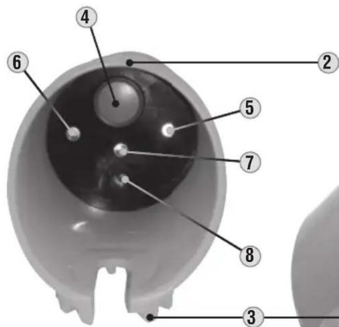
FEATURE DETAILS
- Probe
- Main housing
- Hot stick connection point
- Power/Test button
- Red LED - Voltage Indicator
- Green LED - Power On
- Orange LED – Low Battery
- Buzzer
text_image
Anatomical diagram of the human eye with numbered labels pointing to key structures.
KLEIN TOOLS ON VOLTAGE
EIN SOLS HIGH VOLTAGE CONTACT T
1
FOR USE BY TRAINED PERSONNEL ONLY
Anyone using this instrument should be knowledgeable and trained about the risks involved with measuring medium and high voltage. They must also understand the importance of taking safety precautions as well as testing the instrument before and after using it to ensure that it is in good working condition.
Prior to use, always inspect the tester for visible signs of damage. If there is any sign of damage, or if the tester does not operate correctly, discontinue use.
Always test on a known live circuit to verify tester functionality. The tester should be used as an indication only.
Tester should be kept clean and dry. If it is not, wipe with a clean, dry lint-free cloth.
SITUATIONS TO AVOID
Certain situations and system configurations may cause electrical field interference that could affect the operation of the tester. It is imperative that the user be aware of and identify all such conditions which may exist. Examples of these situations include:
- 90° Corner Configurations – Position the tester to at least 3 ft (1 m) on both sides of corner configurations. Any corner configuration—including conductor configurations, busbar and other electrical apparatus—may cause field cancellation, causing the tester to not operate correctly.
- Same-Phase Interference – When two conductors of the same phase are in close proximity to one another, the field generated could shield the tester, causing it not to operate. Position the tester in areas which will remove it from these situations.
- Opposite Phase Interference – This condition may occur if you're testing a grounded and de-energized conductor which is in close proximity to a live, ungrounded conductor. If you are within the field of the energized conductor, this may cause the tester to indicate that the de-energized line is energized. Attempt to approach the conductor you want to test from outside this possible field.
SELF-TEST
Before using the tester, perform a self-test of the unit. The HVCT1 uses an integrated electronic device to perform a self-check of the correct operation of the indicator and power circuits. This self-test function ONLY confirms battery sufficiency, system integrity, and power is on. Always test on known live circuit to verify tester functionality prior to use, and again after use in the event of indication that voltage is not present.
Press and hold the Power/Test button ④. Look for the red ⑤, green ⑥ and orange ⑦ LEDs to flash, and listen for a beep sound.
When the Power/Test button is released, the tester remains on and ready. The green LED will remain illuminated and the tester remains operative for 2 minutes. When the green LED turns off, the unit is off.
OPERATION
This probe is intended for overhead applications only. See Fig. 1 for ideal detection angle.
Before using the tester, a hot stick or the Klein Tools Telescoping Handle (Cat. No. HV43) must be attached. Only use with hot sticks and rubber gloves meeting industry standards. Always follow approved industry, OSHA and company work
practices & safety procedures when working on or near high-voltage systems.
The HV43 Telescoping Handle may be used up to 10kV AC.
Check to ensure that the metal probe 1 is firmly screwed into the top of the tester before using.
Touch the metal probe directly to the conductor, as close to a 90^ orientation as possible (Fig. 1) Look for the red LED to illuminate and listen for a beep sound, indicating the presence of voltage. If the red LED does not light and the beep does not sound, the conductor may not be energized. Perform the Self-Test again, to ensure the unit is in proper working condition.
Note: in the absence of voltage, the green LED will remain illuminated for up to two minutes to indicate the tester is still on.
When the orange LED is illuminated, this indicates a low battery. Do not attempt to use the tester when the orange LED is lit. See Battery Replacement instructions under MAINTENANCE.

text_image
Ideal detection angle CONDUCTOR 90° HOT STICK V_G Fig. 1MAINTENANCE
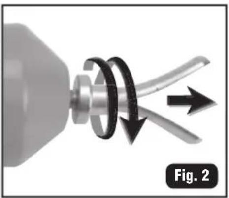
BATTERY REPLACEMENT
- Unscrew the probe from the tester (Fig. 2).
- Slide the inner cylinder out of the main housing (Fig. 3).
- Slide the battery out of its slot (Fig. 4) and replace with a new battery (9V), ensuring connection with correct polarity (Fig. 5).
- Slide the new battery into the slot.
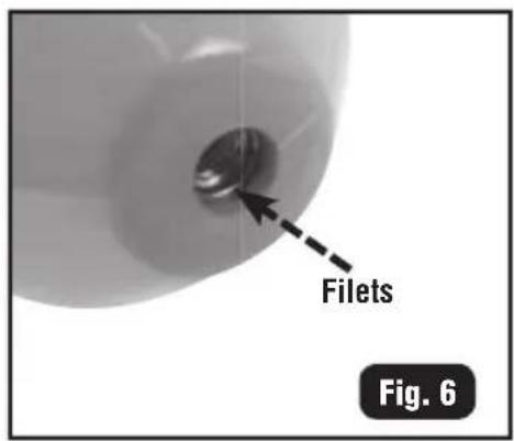
- Slide the inner cylinder all the way into the main housing until the contact screw threads are visible through the top hole of the housing (Fig. 6).
- Screw the probe firmly into place.
natural_image
Mechanical component diagram showing a rotating shaft and curved blades with directional arrows (no text or symbols)
natural_image
Mechanical component with a rotating motor and a close-up view of its internal structure (no visible text or symbols)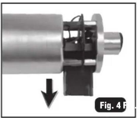
natural_image
Mechanical assembly diagram showing a cylindrical component with internal components and a downward arrow, labeled 'Fig. 4 F' (no text or symbols on the diagram itself)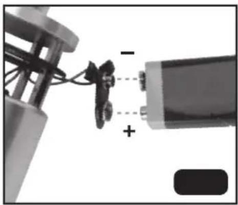
natural_image
Close-up of a mechanical assembly with wires and a battery, showing no visible text or symbols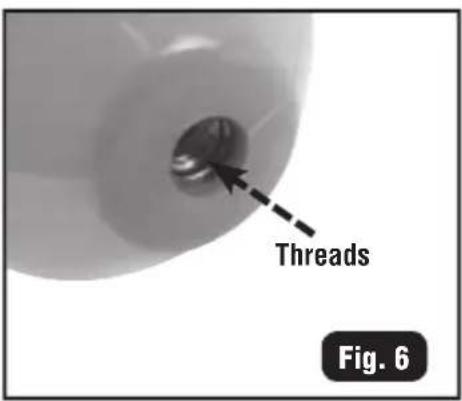
text_image
Threads Fig. 6CLEANING
Be sure tester is turned off and wipe with a clean, dry lint-free cloth. Do not use abrasive cleaners or solvents.
STORAGE
If the tester is not to be used for periods of longer than 60 days, remove the battery and store separately from the tester. Transport and store the tester in the supplied carrying case.
WARRANTY
Do not place equipment and its accessories in the trash. Items must be properly disposed of in accordance with local regulations. Please see www.epa.gov or www.erecycle.org for additional information.
CUSTOMER SERVICE
KLEIN TOOLS, INC.
450 Bond Street
Lincolnshire, IL 60069 USA
hisupport@kleintools.com
www.kleintools.com
natural_image
Mechanical component diagram showing a rotating shaft and flange with directional arrows, labeled Fig. 2 (no text or symbols on the diagram itself)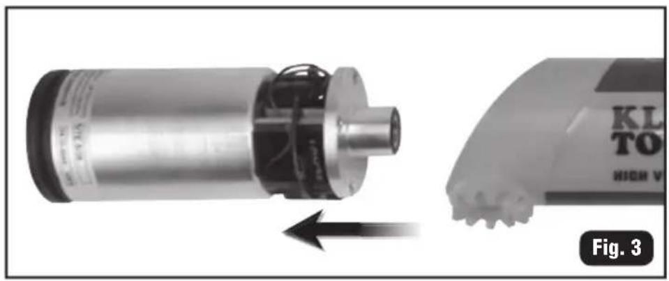
natural_image
Mechanical component with a rotating shaft and housing, shown from an angle to the right (no visible text or symbols)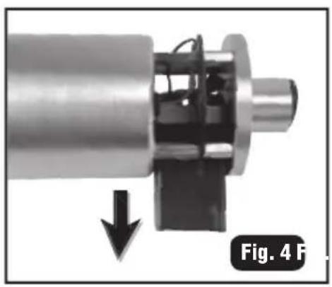
natural_image
Mechanical assembly diagram showing a shaft and housing with a downward arrow indicating force or direction (no text or symbols)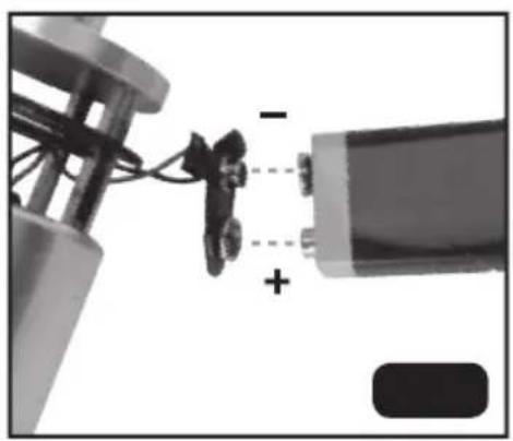
natural_image
Close-up of a mechanical assembly with wires and a battery, showing no visible text or symbols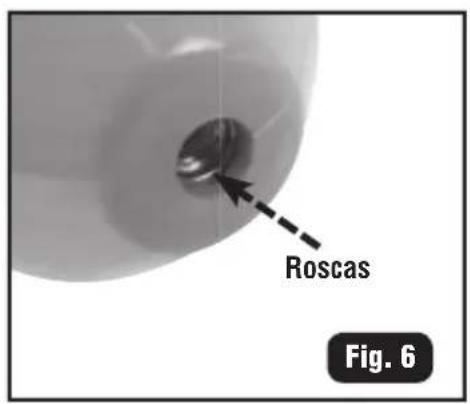
text_image
Roscas Fig. 6LIMPIEZA
natural_image
Mechanical component diagram showing a rotating shaft and curved blades with directional arrows (no text or symbols)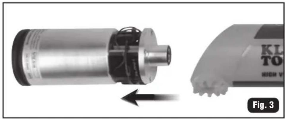
natural_image
Mechanical component with a rotating motor and a close-up view of its base (no visible text or symbols)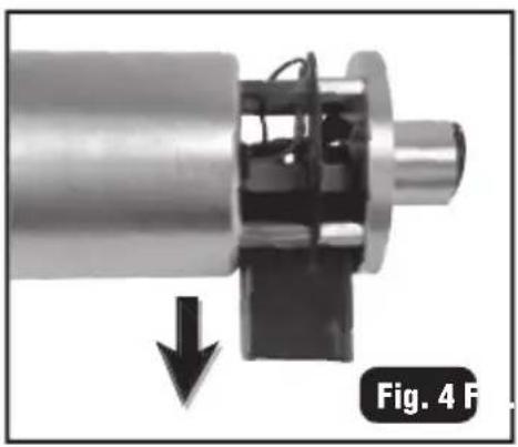
natural_image
Mechanical assembly diagram showing a shaft and housing with a downward arrow indicating force or motion (no text or symbols)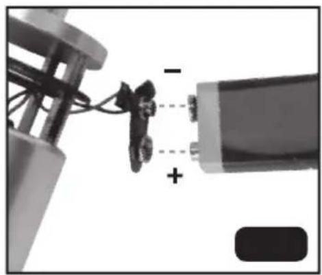
natural_image
Close-up of a mechanical assembly with wires and a battery, showing no visible text or symbols