
UMK 435 UE - Grass trimmer Honda - Free user manual and instructions
Find the device manual for free UMK 435 UE Honda in PDF.

| Product type | Brushcutter |
| Brand | Honda |
| Model | UMK 435 UE (UMK435E1) |
| Engine type | 4-stroke, single cylinder, overhead cam (OHC) |
| Displacement | 35.8 cm³ |
| Net power | 1.0 kW at 7,000 rpm |
| Maximum speed | 10,000 rpm |
| Fuel tank capacity | 0.63 L |
| Oil tank capacity | 0.10 L |
| Recommended engine oil | SAE 10W30 |
| Spark plug | NGK CMR5H |
| Nylon line diameter | 2.7 mm |
| Line length | 3 m |
| Approved cutting tools | Nylon line head, 3/4-tooth blade (max ∅ 255 mm) |
| Tool rotation speed | 7,000 rpm (with blade: 9,200 rpm) |
| Dry weight (without tool) | 7.53 kg |
| Dimensions (L x W x H) | 1,870 x 671 x 521 mm |
| Sound pressure level | 96 dB(A) (at operator position) |
| Guaranteed sound power level | 109 dB(A) |
| Equivalent vibration level | 7 m/s² (depending on configuration) |
| Transmission | Helical bevel gear drive |
| Carburetor | Diaphragm |
| Ignition | Transistorized magneto |
| Idle speed | 3,100 ± 200 rpm |
| Fuel | Unleaded gasoline |
Frequently Asked Questions - UMK 435 UE Honda
User questions about UMK 435 UE Honda
0 question about this device. Answer the ones you know or ask your own.
Ask a new question about this device
Download the instructions for your Grass trimmer in PDF format for free! Find your manual UMK 435 UE - Honda and take your electronic device back in hand. On this page are published all the documents necessary for the use of your device. UMK 435 UE by Honda.
USER MANUAL UMK 435 UE Honda
You have bought a Honda brushcutter and we thank you for the confidence you have shown in us.
The aim of this manual is to help you become familiar with your new machine so that you can use it safely and keep it properly maintained.
To bring our customers the latest technological advances, new equipment and materials and the full benefit of our experience, we regularly improve the models in our product line. As a result, the information and characteristics given in this manual are subject to modification without notice and without any obligation to update the manual.
The illustrations in this manual show the most suitable model to represent the topic dealt with.
If you encounter any problem or have any question regarding your machine, please contact your dealer or an authorized Honda retail agent.
Keep this manual close at hand for ready reference and, if you sell your machine, please make sure you supply this manual with it.
We recommend that your read the terms of guarantee so that you fully understand your rights and responsibilities.
The guarantee is a separate document provided by your dealer.
No part of this publication is to be reproduced without prior written consent.
SAFETY INSTRUCTIONS
For your own safety and operating comfort, it is highly recommended that you read this manual in full.
Pay attention to these symbols and their meaning:
WARNING :
Indicates a high risk of severe personal injury or death if instructions are not followed.
CAUTION:
- Indicates a possibility of personnel injury or equipment damage if instructions are not followed.
NOTE : Source of usefull information.
HOW TO IDENTIFY YOUR MACHINE
 |  |  |  | |
| UEET | ● | ● | ● | |
| U9ET | ● | ● | ● | |
| LEET | ● | ● | ● |
The model of your machine is indicated on its "identification label", by a series of letters and figures (see page 3).

2009 - Honda France Manufacturing S.A.S. - Pôle 45 - Rue des Châtaigniers 45140 ORMES - FRANCE - All rights reserved

OWNER'S MANUAL
Original instructions
UMK425E1-UMK435E1
Brushcutters

natural_image
Technical line drawings of two mechanical components with no visible text or symbolsSAFETY INSTRUCTIONS
All the parts of your machine are potentially hazardous if it is used incorrectly or if it is not properly maintained. Special attention should be paid to sections preceded by the following words.
! WARNING :
Warns against a risk of serious bodily injury or fatal accident if instructions are not complied with.
CAUTION:
- Warns against a risk of bodily injury or equipment damage if instructions are not complied with.
NOTE: Indicates a source of useful information.

This symbol warns you to be especially careful when performing specific operations. See the safety instructions on the following pages with reference to the point or points indicated in the box.
TRAINING
A1. Carefully read the instructions in this manual. Before using your brushcutter, familiarize yourself with how to use it correctly and with its controls. Make sure you know how to stop the engine quickly.
A2. Use the brushcutter for its intended purpose, i.e.:
- Cutting grass with the nylon line attachment along flower beds, shrubberies, walls, fences or lawns and to finish borders after mowing with a lawnmower.
- For cutting tall weeds and brush the 3-tooth blade.
- Using it for any other purpose could be dangerous or result in damage to the machine.
A3. Do not allow children or anyone unfamiliar with the instructions to use the brushcutter. Local legislation may stipulate operator age restrictions.
A4. Do not use the brushcutter in the following circumstances:
- When there are people, especially children, or pets nearby. Comply with the safety perimeter of at least 15 metres between the machine and anyone who may be in the vicinity. The brushcutter is to be operated by one person only.
- If you have taken any medicine or substance which may affect your reactions and judgement.
- If a nylon line cutting head is used, make sure that the guard extension and the line cutter blade are correctly in place in order to ensure correct line length.
- If safety devices such as the cutting attachment guard are missing or if the guard is damaged.
A5. Do not make alterations to your brushcutter. By doing so, you could compromise your safety and expose yourself to serious accident or injury.
A6. Remember that the owner or operator is responsible for any accidents or risks to third parties and their property.
PREPARATION
B1. Do not use this equipment when barefoot or wearing sandals or when wearing loose-fitting clothing that may become snagged on plants. Long trousers, boots or protective footwear with anti-skid soles, goggles or a protective visor, gloves (preferably leather) and ear defenders must be worn when operating the machine. A hard hat should be worn in areas where falling objects may be encountered (such as branches or stones).
B2. Make a thorough inspection of the area to be cleared and remove any objects which could be thrown up by the machine (stones, pieces of wood, wire, bones, etc.).
B3. WARNING: DANGER!
Petrol is extremely flammable.
Store fuel in specially designed containers.
- Refuel the machine outdoors only, with the engine switched off. Do not smoke during refuelling or while handling fuel.
- Never remove the fuel filler cap or fill up the fuel tank when the engine is running or while it is still hot.
- Do not start the engine in the presence of spilled fuel. Move the brushcutter away from the area and avoid creating any source of ignition until the fuel has evaporated and vapours have dispersed.
- Make sure that the caps are securely fitted on the fuel tank and on the fuel can.
B4. Replace faulty exhaust mufflers.
B5. Each time the machine is used, before starting, perform a general inspection and check, in particular, all attachments, cutting assemblies, deflectors and mounting bolts to make sure that they are not worn, damaged or loose. Always check that the gas throttle trigger and the Stop button operate correctly.
B6. Check that the handles and harness attachment point are correctly positioned and that the machine is properly balanced.
The correct positions and adjustments are specified in the section on "Preliminary preparation and checks" in this manual.
B7. Adjust the idle speed so that the cutting attachment stops turning when the throttle control is released.
B8. Install the blade cover on the blade type cutter during removal and installation operations.
- Turn the engine switch to the Stop position and remove the spark plug cap.
- Wear gloves during this operation.
OPERATION
C1. Do not run the engine in a confined space where toxic carbon monoxide fumes may accumulate.
C2. Work by daylight only.
C3. As far as possible, avoid using the machine on wet ground.
C4. When operating the machine, ensure compliance with the safety clearance of the nylon line cutting head with respect to the harness attachment point.
C5. Walk when you use the machine, never run, and stay in a stable position. Beware of obstacles such as stones and tree stumps which could trip you.
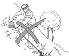
C6. Tread carefully on slopes. When working on slopes, always proceed crosswise: never straight up and down.
C7. Do not use the machine on slopes that are too steep. It is the operator's responsibility to assess the potential hazards of the terrain and to take every necessary precaution for his or her own safety. This is especially important when working on slopes or rough, slippery or loose ground.
C8. Never modify the engine settings in such a way that it runs at excessive speeds.
C9. Before starting the engine, make sure there is no-one within 15 metres of the machine, that the cutting attachment is not touching the ground and that the machine is in a stable position.
C10. Take care when starting the engine. Comply with the safety instructions and stay clear of the cutting attachment.
C11. The engine must be stopped and the spark plug cap removed in the following cases:
- Before performing any servicing action on the cutting system.
- Before cleaning, checking, adjusting or repairing the brushcutter.
- The only adjustments to be carried out with the engine running are carburettor and idle speed adjustments.
- During this operation, make sure the cutting attachment does not strike any object and that the machine is in a stable position.
- If the cutting attachment strikes an object, inspect the cutting system and the transmission shaft to make sure they have not been damaged. Make any necessary repairs before resuming work with the machine.
- If the brushcutter starts vibrating abnormally, look for the cause of the vibrations immediately and take the necessary corrective action.
C12. Stop the engine in the following cases:
- Whenever the brushcutter is left unattended.
- Before refilling the fuel tank.
- When moving the machine from one area to another.
C13. Risk of "kickout" (blade thrust) with all rigid cutting blades.
C14. Using any attachments other than those recommended by Honda may cause damage to your brushcutter, and such damage will not be covered by your guarantee.
MAINTENANCE AND STORAGE
D1. Keep all nuts and bolts securely tightened to ensure safe operation. Regular maintenance is required to ensure safety and optimal performance.
D2. Do not use the machine with damaged or worn parts. Parts must be replaced, not repaired. Use genuine Honda parts. The cutting attachments must always be marked with the manufacturer's brand, the reference and the maximum operating speed. Parts of inferior quality may damage the machine and compromise operator safety.
D3. Wear heavy gloves when removing and installing the cutting device.
D4. Never store the brushcutter with fuel in the fuel tank in a room where fuel vapour could be ignited by a flame, a spark or a source of intense heat.
D5. Store in a clean dry room, out of the reach of children.
D6. Let the engine cool down before putting away the machine in any room.
D7. To reduce fire hazards, remove leaves, grass cuttings and excess oil from the brushcutter, particularly from the cooling fins, the exhaust system and the fuel storage area.
D8. When the machine is stored or carried, the cutting blade must always be covered by its transport guard to avoid any accidental injury.
D9. If the fuel tank has to be drained, this operation must be performed outdoors when the engine is cold.
D10. To protect the environment, do not dispose of old engine oil or fuel by pouring it down the drain, in the gutter or on the ground.
Your local service station can have oil and fuel safely recycled.
SAFETY STICKERS
Your brushcutter must be used with care.
For this reason, adhesive labels in the form of pictograms have been placed on the machine to remind you of the main operating precautions. Their meanings are specified below. These labels are considered to be an integral part of the machine. If any of them comes off or becomes difficult to read, please contact your dealer to replace it. We also recommend that you should carefully read all the safety instructions (see page 2).
Rotating speed
General instructions
![[1] [2] [3]](/content/2026/04/668929/images/3269ce3fe046f10adf1d80809a717490acf5faeafb717dedc38cdbf0d5ed2fb8.jpg)
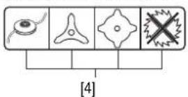
Authorized cutting attachments
![[1] [6] [7]](/content/2026/04/668929/images/243171b9b9cdf87dce8a4442690e2389979fd676d9e39da307c6839fb353c590.jpg)
[1] WARNING: Read the owner's manual before using the machine.
[2] WARNING: Projection hazard. Ensure that all people and animals stay at a minimum distance of 15 m when you operate the machine.
[3] Always wear goggles, a hard hat and any other necessary protective accessories to protect your eyes and body from objects (such as gravel, glass or pieces of metal) thrown up by the cutting attachment.
[4] The brushcutter is to be used with a nylon or a metal disc line cutting attachment only. Do not use a circular saw blade with the standard protector.
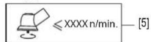
[5] Cutting attachment rotation speed.
[6] The engine emits toxic carbon monoxide. Do not run in an enclosed area.
[7] Petrol is highly flammable. Stop the engine before refueling
IDENTIFICATION OF MACHINE
[A] Identification plate
![Honda France Manufacturing S.A.S. Rue des Châtaigniers - Pôle 45 45140 Ormes - France LWA dB [8] [9] [10] [11] [12] [13] [14] [15]](/content/2026/04/668929/images/0eff214593eac4168b58a3f0275a36e43c5622499289f789d51542de7fd7c693.jpg)
[8] Sound power level garanted according to the directives 2000/14/EC, 2005/88/EC
[9] Conformity mark, according to the directives 98/37/EC, 2000/14/EC, 2004/108/EC, 2005/88/EC, 2006/42/EC
[10] Model - Type
[11] Model - Name
[12] Year of manufacture
[13] Serial number
[14] Conformity mark Russian
[15] Name and address of manufacturer
GENERAL DESCRIPTION
![[17] [18] [A] [16] [20] [19] [22] [25] [30] [32] [23] [24] [26] [27] [29] [31]](/content/2026/04/668929/images/ea38fb5aeac76c4ab2aafb7853be9e0a32cb407e5ab25d1dc733f9a85548cba2.jpg)
![[27] [28] [34] [26] [33] [25] [30] [21] [24] [17] [A] [18] [16] [22] [19] [20]](/content/2026/04/668929/images/e5a10ed4220da0ec4ebf7274e273f2dd1aab16a35bbdc5a9b82551cb8dffe59d.jpg)
IDENTIFICATION OF COMPONENTS
[16] Engine [26] Transmission shaf
[17] Spark plug [27] Transmission head
[18] Recoil starter [28] Nylon line cutting head
[19] Air filter [29] 3-tooth blade
[20] Fuel tank [30] Harness attachment point
[21] Throttle cable [31] Double harness
[22] Clutch housing [32] Bike handle
[23] Control grip [33] Loop handle
[24] Throttle control trigger [34] Line cutter blade
[25] Start / Stop switch
![[40] [37] [41] [38] [36] [35] [39]](/content/2026/04/668929/images/577cd3313e5f6b9a0217dc3cae40b376352f50379f09831fc06337cd56b9d3c9.jpg)
CONTENTS OF BAG
[35] Attachment protector
[36] Screw and spacer
[37] Goggles
[38] 3-tooth blade and its protection
[39] Stabilizer, spacer and nut
[40] Multipurpose wrench
[41] Hexagonal wrench
FITTING
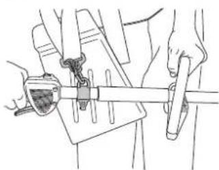
GRIPS AND HANDLES
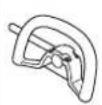
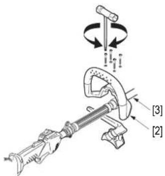
The bike type handle [1] (U type) or the loop handle [2] (L types) must be installed on the transmission tube [3].
![[1] [3]](/content/2026/04/668929/images/974d3f254c8637ff389f19586a41b9390e617313f1d0a7597b3bcd0ff4f925ed.jpg)
CAUTION:
- U types: Position the handle between the two arrows [4]. Fitting is to be performed using the tools in the kit supplied with the appliance.
[5] Spark plug wrench / Torx wrench

ATTACHMENT PROTECTORS
Your brush cutter is supplied with a guard.
Install the guard on the machine with the four screws [8] and the spacer [7] supplied with the Torx wrench.
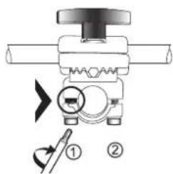
UTILIZATION WITH NYLON LINE CUTTING HEAD
Fit the two sections [10] and [9] and clamp them into place as shown in the diagram. Screw the 3 screws and the washers by using the torx wrench.
UTILIZATION WITH BLADE
Do not fit the lower section [10].

A1
A4
B3
C11
![[4]](/content/2026/04/668929/images/e733ae25b635f73ce6997aa245b3a508108f6e114d00f3174182b3424269518f.jpg)
[6] Hexagonal wrench

![[7] [8]](/content/2026/04/668929/images/a3b6aabedd28ab02f24ee7c790faa844f7e199dd756c2335b40a69e33ad56ae3.jpg)
![[9] [10] [9] [10]](/content/2026/04/668929/images/6ad8d65ebaf024fcffc6c5dffcc251578037433eb25e60af9b25a3dc80eb678a.jpg)
WARNING :
Never use the grass/weed trimmer without its debris shield. Stones or other foreign objects thrown outward by the wheeling cutting attachment (nylon-line, cutting head or cutting blade) or contact with the wheeling cutting attachment could cause personal injury or property damage.

SAFETY
ASSEMBLING THE CUTTING SYSTEM
CAUTION:
- Pay special attention when fitting the spacer [13]. The concave side must face the transmission [15].
NYLON LINE CUTTING HEAD
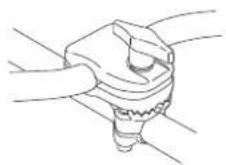
With the spacer [13] already fitted on the transmission shaft, screw on the nylon line cuttinghead. It is tightened by turning counterclockwise.

B8
C11 D3
![[14] [15] [13]](/content/2026/04/668929/images/4a155d7bdf547fe80a1a403e7f0e7dfe0c414a31e685c29262629149a34a55be.jpg)
Use the hexagonal wrench [14] to immobilize the transmission so that the nylon line cutting head is properly tightened.
3 - TOOTH BLADE
Place the grass-cutting disc [16] between the spacers [13] and [17] so that the grooves on the spacers fit perfectly onto the shaft.
Install the stabilizer [18]. Block the rotation of the shaft with the hexagonal wrench [14]. Securely tighten the locknut [19] in the counterclockwise direction with the appropriate wrench.
FITTING AND ADJUSTING THE HARNESS
! WARNING :
For operator safety and comfort, it is important to adjust the harness straps so they can be worn comfortably and so that the machine is properly balanced in the working position.
Machines are supplied with a double harness [22].
Put on the harness and fasten it with the quick fastener [23].
Adjust the straps with the buckles [24] so that the machine hangs at hip height.
![[14] [13] [16] [17] [18] [19]](/content/2026/04/668929/images/ef09f59b710d565446db987dd0eec9c678f764dd0c557465c386b18ea3a89042.jpg)
![[22] [24] [24] [23]](/content/2026/04/668929/images/0bbf4d085da794523c8888edd16d1042b9b37c987867783e2956a8dadbe7b424.jpg)
PRELIMINARY PREPARATION AND CHECKS
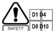
BALANCING THE MACHINE
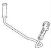
Attach the brush cutter as illustrated [1].
Once the machine is in place, it is essential to check that it is correctly balanced. This check must be performed with the cutting attachment fitted on the appliance and with the fuel tank half-full.
Adjust the length of the harness so that the cutting attachment is parallel to, and in contact with, the ground.
[1]
natural_image
Line drawing of hands using a tool to adjust or install a mechanical component (no text or symbols visible)When the machine is equipped with a grass-cutting disc, the disc must be fitted with the stabilizer (see page 4).
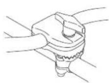
Correct balancing is obtained when the stabilizer just gently touches the ground [2].

natural_image
Illustration of a person using a long pole-mounted tool on grass, with no visible text or symbols
natural_image
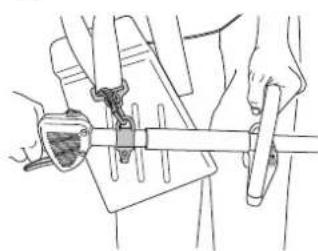
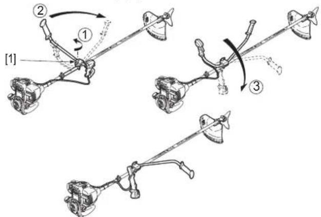
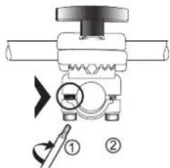
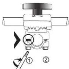
Illustration of a person using a manual power tool on grass, with no text or symbols present.It must be possible to raise the cutting attachment off the ground with only a slight effort on the handles. If adjustment is required, move the attachment point [4] forwards if the cutting attachment feels too heavy or rearwards if it feels too light. Loosen the bolts with the Torx wrench [3] supplied to move the harness attachment point to the desired position.
![[3] [4] [5]](/content/2026/04/668929/images/3d848e7e16f11553ccc934c69c2e4999490fea666edfe9f87c59c5edc967b83d.jpg)
![[5] [3] [3] [4]](/content/2026/04/668929/images/43f1f3071ef2565ad1e551560633feaf6320eacd4adcce154970e517fbb6a7b6.jpg)
CAUTION: (U type)
- Be careful not to pull the throttle cable too tight when moving the handle [5]. Check that the throttle trigger operates smoothly.
Adjust the position of the loop handle or the bike handle [5] by loosening the four bolts to obtain a comfortable operating position. When you have found the ideal position, check the balance again and adjust if necessary.
Then securely tighten the bolts to lock the handle in position.
For reference, the standard adjustments are as follows for the specified types of brushcutter:
![[6] [7]](/content/2026/04/668929/images/d54346ce5992ed985a9f97f3f6af28c45683cfe3043d9f00dd0bed14debad4dc.jpg)
| UMK425E1 UMK435E1 | ||
| L type | ||
| [6] 530 mm 545 mm | ||
| [7] 760 mm 775 mm | ||
![Technical diagram showing mechanical assembly with labeled parts [8] and [9], including a bolt and shaft assembly.](/content/2026/04/668929/images/d8efc37039064c3b18564e0c33da0ede961a5a169a1b01b1cc6c41c956280cc8.jpg)
| UMK425E1 UMK435E1 | ||
| U type | ||
| [8] 490 mm 500 mm | ||
| [9] 740 mm 750 mm | ||
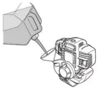
FILLING THE FUEL TANK

WARNING :
The pressure inside fuel tanks may increase when the ambient temperature rises. The cap should be removed with care to avoid any splashing of fuel. Fuel should be stored in a cool place, for short periods of time, and must never be left in direct sunlight.
natural_image
Illustration of a hand pouring liquid into a mechanical device (no text or symbols visible)| UMK425E1 UMK435E1 | ||
| Tank capacity | 0.58 (580 cc) | 0.63 (630 cc) |
| Recommended fuel Premium unleaded | ||
CAUTION:
- Clean the fuel tank cap and its edges to prevent foreign bodies from entering the tank.
- Fill the fuel tank with a suitable funnel or a jerrycan with a suitable spout.
- For easy filling, place the machine in the operating position.
- Make sure that the machine remains in a stable position throughout this operation so that it does not fall over.
WARNING :
Petrol is extremely flammable and, in some circumstances, it is explosive.
Fill the fuel tank in a well ventilated area with the engine switched off.
Do not smoke and avoid any flames or sparks in the area where filling is performed and where the fuel is stored.
Do not overfill the fuel tank. (The fuel level must be below the filler neck).
After filling the tank, make sure that the tank cap is correctly fitted.
Take care not to spill fuel during the tank filling operation.
Petrol splashes or vapours could catch fire.
Make sure that any spilled petrol has evaporated and that vapours have dispersed before starting the engine.
Avoid direct contact of petrol with the skin and do not breathe the vapours.
KEEP FUEL OUT OF REACH OF CHILDREN.
FUEL CONTAINING ALCOHOL
If you intend to use fuel with alcohol, ensure that its octane number is at least as high as that recommended by Honda (86). There are two types of fuel/alcohol mixtures: one contains ethanol and the other methanol.
Do not use mixtures containing more than 10% ethanol, or fuel containing methanol (methyl or wood alcohol), which do not contain cosolvents, or corrosion inhibitors for methanol.
In the case of a mixture containing methanol with addition of cosolvents and corrosion inhibitors, limit the proportion to 5% of methanol.
NOTE: The guarantee does not cover damage caused to the fuel system or engine performance problems resulting from the use of fuel containing alcohol. Honda does not give its approval to the use of fuels containing methyl alcohol since their suitability is not yet proven.
FILLING THE OIL TANK
! WARNING
The engine may be seriously damaged if it is run with insufficient oil.
Check the oil level on a flat horizontal surface with the engine switched off. The engine's service life may be shortened if non-detergent oil or 2-stroke engine oil is used.

CHECKING THE OIL LEVEL
-
Place the engine in a horizontal position on a flat surface.
-
Remove the oil filler cap and check the oil level: oil must be level with the top of the oil tank neck [1].
-
If the level is too low, top up with the recommended oil to the top of the oil filler neck. Use Honda 4-stroke oil or an equivalent engine oil with high detergent properties, of prime quality and certified as complying with American automobile manufacturer standards for SG and SF classification.
! WARNING
The machine must always be resting on the ground when starting up. Make sure that it is stable and that the cutting attachment is not touching other objects or the ground.

BEFORE STARTING UP
Check that the guards are properly fitted and tightened and that you have the necessary protective equipment such as goggles, gloves, boots and ear-defenders.
natural_image
Illustration of a person using a tool to cut a tree trunk, with no visible text or symbolsChek that the cutting attachment and the grips or handle are correctly tightened. Move the machine away from the location where the fuel tank was filled.
Stand on flat, stable ground. Check that the spark plug cap is in place.

natural_image
Illustration of a person using a metal detector to measure a child's weight in a field (no text or symbols)STARTING AND STOPPING THE ENGINE

COLD START
The machine is considered to be "cold" if the engine has not been running for more than 5 minutes in the 10 minutes before starting up.
NOTE: If the ambient temperature is warm enough (summer), the engine may start without applying the choke.
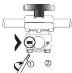
START THE ENGINE AS FOLLOWS:
![[2] [2]](/content/2026/04/668929/images/2271c2ad795779b15a94e700f92cd59f8e7b3e7e60ccb264b117c8c5441edf0c.jpg)
- Place the Start/Stop button [2] in the Start position "I".
- Place the choke lever [3] in the high position (closed).
- Press the primer pump button [4] located below the carburettor several times to prime the engine.
![[3] [4]](/content/2026/04/668929/images/4eb03dde3076eb7a8130581e7d2b54a895c9b67efa29cf38cdcbe332a860c896.jpg)
-
Gently pull the recoil starter [5] until you feel resistance.
-
Then pull vigorously until the engine starts.
-
When the engine has started, return the choke lever [3] to the low position.
![[5]](/content/2026/04/668929/images/c44edc5eb52f319599cb0869bc3bb26600d7823799344b4872b57c5a114ffc9c.jpg)
CAUTION:
- Do not pull the recoil starter cord all the way out.
- Do not release the recoil starter suddenly so that it strikes the engine. Return it gently to avoid damaging the starter mechanism.
NOTE: Always pull the recoil starter vigorously. If you pull too gently, sparks may not be produced on the spark plug and the engine will not start. Do not place your foot or knee on the transmission tube to hold the machine, as this could bend the tube, rendering the machine inoperable.
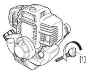
HOT START
The machine is considered to be "hot" if the engine has been running for more than 5 minutes in the 10 minutes before starting up.
The hot start procedure is the same as the cold start procedure except that the choke [1] is not needed. (The lever must be left in the low position).
![[1]](/content/2026/04/668929/images/dafa0e27fe89a99b1fa3b8e9e2ecae75fcd555c39bcf7facb1cd6027359690e2.jpg)
NOTE: Should you have difficultie store-start a hot engine, follows this procedure:
- Turn the engine to the OFF position (O).
- Make sure that the choke lever is in OPEN position.
- Keep the throttle control lever (throttle trigger) fully squeezed.
- Pull the starter grip 3 to 5 times, and release the throttle control lever (throttle trigger).
- Start the engine referring to the procédures described above.
CAUTION:
- Be sure to turn the engine switch to the OFF position (O).
- If this operation is executed with the engine switch at the ON position, the blade may rotate when the engine starts and a personal injury may result.
STOPPING THE ENGINE
![[2] [2]](/content/2026/04/668929/images/01a86d12ce6c41833805766947ebc16f4725cbee0d52e7f9abc13b56ebd0f463.jpg)
- To stop the engine, press the Start/Stop button to engage the Stop position (O) [2].
- This step can also be taken to stop the machine in case of emergency.

WARNING:
Note that the cutting attachment continues turning by inertia after the engine has been stopped.
OPERATION

Read the safety instructions
OPERATING POSITION
Once the machine has been started, attach it to the harness as already described in the section on preparation.

WARNING:
When handling the machine, take care to avoid striking any objects with the cutting attachment and keep the cutting attachment away from your body. Do not use the machine unless it is attached to the harness.
Hold the brush cutter firmly by both grips as shown. Always keep firm footing on both feet when working. Take appropriate breaks and vary your working position.
CAUTION:
- When using the machine, always allow the engine to idle between operations. If the machine is allowed to run at maximum speed with no load (no resistance on the cutting attachment) for long periods, the engine may be seriously damaged.

natural_image
Two identical line drawings of a person using a handheld metal detector, shown from different angles (no text or symbols)WITH NYLON LINE TYPE CUTTING HEAD

A4 C11
This attachment is designed to complete the job done with a lawnmower. It is especially handy and efficient for cutting grass along walls or fences, around trees or posts and on narrow or where a lawnmower cannot be used.

WARNING
Make sure the line cutting blade is properly mounted on the cutting attachment guard.
LINE LENGTH ADJUSTMENT
At maximum rotating speed, gently press the nylon line cutting head on the ground. The line is automatically extended. Repeat this operation until the optimal length is obtained.
When the engine is started and the cutting attachment starts rotating, the excess line will automatically be cut by the line cutter located on the guard.
CUTTING
The nylon line cuts grass cleanly without damaging tree bark and avoiding the violent impacts that would occur between a rigid cutting attachment and hard surfaces.
It is, however, recommended not to work too long in such areas in order to avoid damaging fragile, immature plant, in particular, and to avoid premature line wear.
Proceed in stages, when trimming, tilting the cutting attachment slightly.
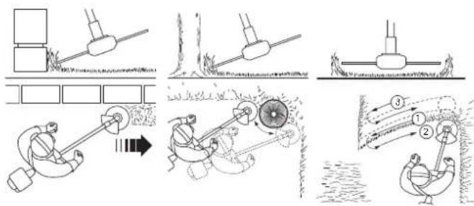
For larger areas, hold the cutting attachment horizontal and sway it sideways from right to left and from left to right, alternately.
WITH 3-TOOTH AND 4-TOOTH BLADE

CAUTION:
- Do not use a blade larger than 255 mm in diameter.

CUTTING
The 3-tooth and 4-tooth grass-cutting blade is especially suitable for clearing dense and tangled weeds, bushes such as brambles or wild shrubs with a stem diameter of less than 2 cm.
To trim bushes, lower the cutting attachment from above while holding it horizontal so as to cut the branches in small pieces.
WARNING :
It is dangerous to use grass-cutting blades on very hard wood and/or plants with a large stem diameter. Kicking of the cutting attachment is difficult to control, and can seriously endanger the operator and cause serious damage to the equipment.
MAINTENANCE
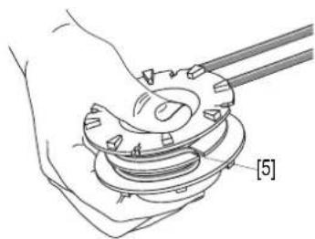
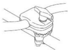
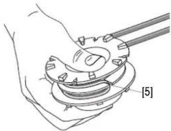
REPLACING THE LINE
- Press the lugs [2] located on either side of the head to open it.

-
Extract the reel and remove the rest of the nylon line.
-
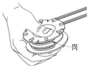
Prepare 3 metres of 2.7 mm diameter line and fold it in half, lengthwise.
-
Place the middle of the line in the notch [5] in the reel and coil the wire by turning in the specified direction.
-
Secure the ends in the two opposite notches [3] (leaving an excess of 10 cm of line).
-
Reinstall the reel in its place and feed the lines through the two side holes [4].
-
Reinstall the cover.
![[2] [3] [4]](/content/2026/04/668929/images/52b5fdb494dc4906ac02719364dd234ac63a3d00493d298d51a73d58dae6c7d0.jpg)
natural_image
Hand holding a mechanical component with two rods, labeled [5] (no text or symbols on the diagram itself)CAUTION:
• Always use a line of the diameter recommended in the technical specifications.
- Poor results would be obtained if the line diameter is too large as this will result in an excessive load on the engine, so reducing its performance.
WARNING :
Never replace the nylon line with a line of a different material, such as steel wire.
To avoid severe personal injury, disconnect the spark plug cap to prevent accidental starting.
Wear heavy gloves to protect your hands when replacing the nylon head.
SHARPENING
3-TOOTH AND 4-TOOTH BLADES

Sharpening is essential to obtain good results. A slightly blunt cutting attachment can be sharpened with a file.
A grinding wheel should be used if the wear is more severe.
CAUTION:
- In all cases, the cutting attachment must be kept correctly balanced. If you do not have the required tools or if you think your cutting attachment may not be properly balanced, contact your authorized Honda dealer.
Remove the cutting attachment for sharpening and check that it is not cracked, out of true or bent.
If it is, replace it with a new one.
Both sides of 3-tooth and 4-tooth blades can be used.
When one side is worn, the cutting attachment should be turned over to use the cutting edges on the other side.
Only the bevelled edges of the teeth are to be sharpened.
It is important to keep their profile regular and to avoid incipient fractures.
All the teeth must be sharpened in the same way.
NOTE: If the machine vibrates abnormally after sharpening, this indicates that the blade is unbalanced. In this case, contact your authorized dealer Honda to have it checked.
CAUTION:
- Replace the blade when the wear limit shown in the illustrations below has been reached.
[A] Unsatisfactory
[1] Incipient fracture
[2] Limit exceeded and tooth profile irregular
[3] Angles incorrect and unequal
[4] Unsatisfactory cutting profile
![[A] 😊 [2] [1] [3] [4]](/content/2026/04/668929/images/5c7d338a3ddf0f2e03bca784a671077efe25045eca92067d0de237fd962c777e.jpg)
[B] Satisfactory
[5] Sharpening limit
![30 mm [5] [30° 30° 30° 30° [B]](/content/2026/04/668929/images/fef7b11d217aec3c0c1a1dcf0a054388855f081997660d51bb88308c5d189733.jpg)
ADJUSTING THE CARBURETOR
PROCEDURE
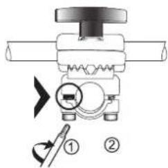
Start the engine and let it warm up to normal operating temperature. Then turn the idle screw [7] to the right or left to obtain the correct setting.
![[7]](/content/2026/04/668929/images/d17a81d569cd6d840af61883298ac0973b9119323480abce7d98b5950bb8fa37.jpg)
UMK425E1 UMK435E1
Idle speed 3 100 ± 200 rpm.
NOTE: When the engine is idling, the cutting attachment must not rotate.
CHECKING THE SPARK PLUG

- To reach the spark plug [8], the top cover must be removed from the engine [9]. Use the hexagonal wrench supplied to undo the bolt [10].
![[8] [9] [10]](/content/2026/04/668929/images/665f481b6fcf77907a68d6fa0c8e403ae2d7ed62509c87c2d30a6c1e8bb0c254.jpg)
NOTE: Hot parts and moving parts (flywheel) are exposed when the engine top cover is removed. Never use your brush cutter with the engine cover removed.
- Remove the cap and unscrew the spark plug using the wrench supplied.
- Clean the electrodes with a wire brush [11] to remove carbon deposits.
- If the electrodes show signs of wear, replace the spark plug with a new one with the same characteristics.
- Check the spark plug gap with feeler gauges [12]. When adjustment is required, carefully bend the side electrode.
- Reinstall the spark plug and screw it finger-tight onto its seat.
- For new spark plugs, tighten by an additional 1/2 turn with the spark plug wrench. When the same spark plus is installed, 1/8 to 1/4 of a turn is enough.
![[11] 0,6-0,7 mm [12]](/content/2026/04/668929/images/e81da119a0c6c9605232abb5f8a405b854c618c75845cb54d8892efbca4a0db5.jpg)
CAUTION:
- If a spark plug is insufficiently tightened, it is liable to heat up and damage the engine. If the spark plug is overtightened or cross-threaded, irreparable damage could be caused to the engine block.
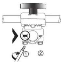
ENGINE OIL CHANGE

NOTE: Drain the oil while the engine is still warm to assure rapid and complete draining.
natural_image
Technical line drawing of a mechanical pump or motor assembly (no text or symbols)![[2] [3]](/content/2026/04/668929/images/051e8c6457e830657432a8069e893e07c4dbb19154265121a1113f75db03d8b9.jpg)
- Check the fuel tank cap [2] is tightened.
- Remove the oil filler cap [1] and drain the oil into the oil container by tipping the engine toward the oil [3] filler neck.
- Refill with the recommended and check the oil level [4] (see page 6).
![[1] [4] [4] [4]](/content/2026/04/668929/images/4d183da6965f2b5c32da9706077de9664c53adabf536eb3fb4c04666f4d2e216.jpg)
| UMK425E1 UMK435E1 | ||
| Engine oil SAE 10W30 | ||
| Oil tank capacity | 0,08 (80 cc) | 0,10 (100 cc) |
- Install the oil filler cap [1].
CAUTION:
- Wash your hands with soap and water after handling used oil.
NOTE: Please dispose of used motor oil in a manner that is compatible with the environnement. We suggest you take it in a sealed container to your local service station for reclamation. Do not throw it in the trash or pour it on the ground.
AIR CLEANER MAINTENANCE
The foam air filter element must be cleaned regularly to prevent impurities from entering the engine and causing premature wear. A dirty air filter will reduce engine power and increase fuel consumption.
CAUTION:
- Never run the engine without the air filter, as this could cause premature wear of the engine.
- Open the air filter cover [5] and remove the filter [6] from the filter housing [7].
![[5] [6] [7]](/content/2026/04/668929/images/7cd40637f3e599ae6de8632c8fa70cc5a6d0c42937d28d377c673acdf43c93b2.jpg)
- Clean the filter with warm soapy water or in a nonflammable solvent and then leave to dry.
- Dip the element in clean engine oil and squeeze out the excess oil.
- Reinstall the foam filter element and the filter cover.
LUBRICATING THE TRANSMISSION HEAD
![[8] [9]](/content/2026/04/668929/images/3a3e75c1b8aa6377c4cb7f948442ffeac734eeeee9a00c4696f3417a3f698836.jpg)
- Remove the bolt [9] from the transmission head.
- Insert the nozzle of the tube of special lithium grease (available from your Honda dealer) and fill with grease while turning the cutting attachment so that the grease is properly distributed. Continue until grease comes out of the bolt hole [8].
- Reinstall the bolt and tighten moderately.
MAINTENANCE SCHEDULE
| Maintenance to be carried out at the intervals indicated in months or in operating hours which ever occurs first. | Frequency | ||||
| Each time used | Every 3 months or 25 hours | Every 6 months or 50 hours | Every year or 100 hours | ||
| Engine cooling fins | Clean | ||||
| Condition of cutting attachment and guard | Check | ||||
| Zone around transmission head | Clean | ||||
| Transmission head | Grease | ||||
| Operation of throttle trigger | Check | ||||
| Operation of Stop button | Check | ||||
| Idle / Clutch Check | |||||
| Air filter element | Check | ||||
| Clean (1) | |||||
| Air filter housing | Clean | (1) | |||
| Zone around spark plug | Clean | ||||
| Spark plug | Check | ||||
| Clean | |||||
| Zone around carburettor | Clean | ||||
| Cables and connections | Check | ||||
| Fuel system Check Every 2 years (replace if necessary) (2) | |||||
| Fuel filter Check | (2) | ||||
| Spring and clutch pads | Check (2) | ||||
| Idle speed | Check | (2) | |||
| Adjust | (2) | ||||
| Engine oil | Check | ||||
| Replace | Replace after 10 service hours and then every 6 months or 50 service hours | ||||
| Fuel tank Clean | |||||
| Valve clearance | Adjust | (2) | |||
| Nuts and bolts | Check / Tighten | ||||
(1) Clean more often in dusty environments.
(2) Maintenance of these points must be carried out by a Honda dealer.
TROUBLESHOOTING
Problem Probable cause Page
Engine does not start. 1. No fuel. 5
| Intervention | 2. Start/Stop button is in Stop position. | 6 |
| 3. Spark plug cap incorrectly attached or disconnected. | 9 | |
| 4. Faulty spark plug or incorrect gap. | 9 | |
| 5. Engine flooded. Remove spark plug, dry it with a cloth and reinstall it. | 9 | |
| 6. Fuel filter is dirty. Clean it. | - | |
| Starting difficult or loss of power. | 1. Dirty air filter. | 10 |
| 2. Impurities in fuel tank. | - | |
| 3. Water in fuel tank and in fuel. | - | |
| 4. Fuel tank cap vent and /or carburettor clogged. | - | |
| 5. Engine is hot; choke is closed. Open choke. | 7 | |
| Uneven running. | 1. Faulty spark plug or incorrect gap. | 9 |
| 2. Dirty air filter. | 10 | |
| Engine overheats. | 1. Spark plug gap incorrect. | 9 |
| 2. Dirty air filter. | 10 | |
| 3. Engine cooling fins clogged. | - | |
| 4. Oil level too low. | 6 | |
| 5. Starter pulley fouled by grass cuttings, etc. | ||
| Brush cutter vibrates excessively. | 1. Blade incorrectly balanced or cutting attachment incorrectly fitted. | 3 |
| 2. Engine bolts loose. | - |
TRANSPORT AND STORAGE
TRANSPORT
WARNING :
When transporting or carrying your brush cutter, the engine must always be stopped and the transport guard must be installed on the cutting attachment.
When carrying your brush cutter, hold it by the transmission tube in a balanced position. If it is to be transported in a vehicle, make sure that it is properly secured so it cannot move. It must be positioned so that there is no risk of fuel leakage.

natural_image
Line drawing of a person walking with a long tool, no text or symbols presentSTORAGE
If the machine is not to be used for more than two months, the following storage precautions should be taken:
- Drain the fuel tank and run the engine to empty the carburettor.
- Remove the spark plug and pour a few drops of oil (same quality as that used in the engine) into the cylinder.
- Gently pull the recoil starter to distribute the oil in the cylinder and on the piston. Then reinstall the spark plug.
- Clean the whole machine, paying special attention to plant residues accumulated around the cutting attachment, in the engine cooling fins and under the cowlings.
- Using a paint brush, apply a thin film of standard oil over the metal cutting attachments to prevent corrosion.
- Store the machine in its packaging, in a cool dry place.
- If the machine is to be stored in a vertical position, place it with the engine at the bottom so that it will not topple over.
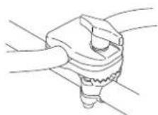
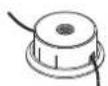
FOLDING THE HANDLE (U TYPE ONLY)
For easier storage, the handle on your brushcutter can be swivelled round. Proceed as described below.
CAUTION:
- Turn the handle the clockwise only.
- Never swivel the handle through more than a quarter of a turn.
- Do not unscrew the knob [1] by more than 6 turns.
flowchart
graph TD
    A["Component 1"] --> B["Component 2"]
    B --> C["Component 3"]
    C --> D["Component 4"]
USING THE AFTER A STORAGE PERIOD
- Remove the spark plug, check that it is clean and that the electrode gap is correct. Pull the starter several times.
- We recommend that the spark plug be screwed down as far as possible by hand until finger tight; then use a plug spanner to tighten it by an extra 1/8 or 1/4 turn.
- Check the level and condition of the engine oil.
- Fill the fuel tank and start the engine.
NOTE: If the cylinder has been coated with oil, the engine will smoke on start-up. This is normal.
FUEL STORAGE
NOTE:
- Ensure that you use containers or drums specifically designed for hydrocarbons [2]. This will prevent polluting the fuel through the dissolution of the container walls, which will lead to poor functioning of the engine.
- The warranty does not cover a blocked carburetor or valves jammed by old or polluted fuel.
- The quality of unleaded petrol alters very quickly (2 to 3 weeks in some cases). Do not use fuel more than 1 month old. Store the absolute minimum required for your monthly consumption.

[2]
ACCESSORIES
CURRENT PARTS, CONSUMABLES
Various accessories are supplied with the machine or are available as options, depending on the model.
| UMK425E1 UMK435E1 | |||
| LEET UEET LEET U9ET | |||
| Mowing and clearing: | |||
 | 72560-VL6-P31 | ||
| Standard | |||
| Thorny hedges and brush: | |||
 | 72511-VL6-P31 (∅ 255) | ||
| Standard | |||
| Large areas of grass: | |||
 | 72511-VF9-E32 (∅ 230)72512-VL6-P31 (∅ 255) | ||
| Optional | |||
| Current parts | |||
 | 17211-Z0H-000 | 17211-Z0Z-000 | |
| Air filter | |||
 | 31915-Z0H-003 | ||
| Spark plug | |||
 | 28462-ZM3-003 | ||
| Recoil starter | |||
| Consumables | |||
 | 08221-888-010MP | ||
| Engine oil | |||
WARNING :
For your safety, it is strictly prohibited to install any other attachment than the ones listed above and especially designed for your brushcutter's model and type.

TECHNICAL SPECIFICATIONS
| MODELS | UMK425E1 | |
| UEET LEET | ||
| GENERAL CHARACTERISTICS | ||
| Description code HAJF HAHF | ||
| Function Cutting of brush | ||
| Dimensions L x W x h mm | 1 859 x 671 x 517(1 888 x 671 x 504)* | 1 859 x 384 x 252(1 888 x 384 x 247)* |
| Empty weight (without cutting attachment) kg 6.28 5.98 | ||
| ENGINE | ||
| Model GX25T | ||
| Description code GCALT | ||
| Type 4 stroke, overhead-camshaft, single cylinder | ||
| Displacement cc | 25 | |
| Bore / Stroke mm | 35 x 26 | |
| Net power** (ISO 8893) kW/rpm | 0.72 / 7 000 | |
| Net Torque max.of engine** (SAE J1349) N.m | 1.0 / 5 000 | |
| Maximum speed rpm | 10 000 | |
| Idle speed rpm | 3 100 | |
| Engine oil | SAE 10W30 | |
| Oil tank capacity ℓ (cc) | 0.08 (80) | |
| Fuel | Unleaded | |
| Fuel tank capacity ℓ (cc) | 0.58 (580) | |
| Ignition | Transistorized magneto ignition | |
| Spark plug brand and type | NGK CM5H | |
| Carburettor | Membrane | |
| Transmission | Helical-toothed bevel gear | |
| Gear ratio | 14 / 19 | |
| Cutting attachment rotation speed rpm | 7 000 / (9 200*) | |
| Length of nylon line ∅ 2,7 (standard) m | 3 | |
| Consumption g/kWh | 340 | |
* Values in brackets: machine fitted with 3-tooth disc, 4-tooth disc.
** The power rating of the engine indicated in this document is the net power output tested on a production engine for the engine model GX25T and measured in accordance with ISO8893 at 7 000 rpm (Net Power) SAE J1349 and 5 000 rpm (Net Torque max.). Mass production engines may vary from this value. Actual power output for the engine installed in the final machine will vary depending on numerous factors, including the operating speed of the engine in application, environmental conditions, maintenance, and other variables.
| UMK425E1 | |||||
| LEET | UEET | ||||
 |  |  |  |   | |
| Equivalent sound pressure level at operator station (as per EN ISO22868: 2008) dB(A) | 95 | 94 | 95.5 | 94 | |
| Measuring uncertainty dB(A) | 1.5 | 1 | 1 | 1 | |
| Measured sound power level (as per standard EN ISO22868: 2008) dB(A) | 104 | 103.5 | 104.5 | 104 | |
| Measuring uncertainty dB(A) | 1.5 | 1 | 1.5 | 1 | |
| Guaranteed sound power level (as per directives 2000/14/EC, 2005/88/EC) dB(A) | 109 | ||||
| Equivalent vibration level (as per standard EN ISO22867: 2008, EN 12096: 1997) m/s ^2 | 10 | 10 | 4 | 5 | |
| Measuring uncertainty m/s ^2 | 3 | 5 | 2 | ||
| MODELS | UMK435E1 | |
| U9ET LEET | ||
| GENERAL CHARACTERISTICS | ||
| Description code HALF HAKF | ||
| Function Cutting of brush | ||
| Dimensions L x W x h mm | 1 870 x 671 x 521(1 899 x 671 x 507)* | 1 870 x 384 x 258(1 899 x 384 x 257)* |
| Empty weight (without cutting attachment) kg 7.53 7.22 | ||
| ENGINE | ||
| Model GX35T | ||
| Description code GCAMT | ||
| Type 4 stroke, overhead-camshaft, single cylinder | ||
| Displacement cc | 35.8 | |
| Bore / Stroke mm | 39 x 30 | |
| Net power** (ISO 8893) kW/rpm | 1.0 / 7 000 | |
| Net torque max. of engine** (SAE J1349) N.m | 1.6 / 5 500 | |
| Maximum speed rpm 10 000 | ||
| Idle speed rpm | 3 100 | |
| Engine oil | SAE 10W30 | |
| Oil tank capacity ℓ (cc) | 0.10 (100) | |
| Fuel | Unleaded | |
| Fuel tank capacity ℓ (cc) | 0.63 (630) | |
| Ignition | Transistorized magneto ignition | |
| Spark plug brand and type | NGK CMR5H | |
| Carburettor | Membrane | |
| Transmission | Helical-toothed bevel gear | |
| Gear ratio | 15 / 20 | |
| Cutting attachment rotation speed rpm | 7 000 / (9 200*) | |
| Length of nylon line ∅ 2,7 (standard) m | 3 | |
| Fuel consumption g/kWh | 360 | |
* Values in brackets: machine fitted with 3-tooth disc, 4-tooth disc.
** The power rating of the engine indicated in this document is the net power output tested on a production engine for the engine model GX35T and measured in accordance with ISO 8893 at 7 000 rpm (Net Power) and SAE J1349 at 5 500 rpm (Net Torque max.). Mass production engines may vary from this value. Actual power output for the engine installed in the final machine will vary depending on numerous factors, including the operating speed of the engine in application, environmental conditions, maintenance, and other variables.
| UMK435E1 | |||||
| LEET | U9ET | ||||
 |  | [HXY] |  |   | |
| Equivalent sound pressure level at operator station (as per EN ISO22868: 2008) dB(A) | 96 | 95.5 | 96 | 94 | |
| Measuring uncertainty dB(A) | 1 | ||||
| Measured sound power level (as per standard EN ISO22868: 2008) dB(A) | 105 | 103 | 105 | 103 | |
| Measuring uncertainty dB(A) | 1 | ||||
| Guaranteed sound power level (as per directives 2000/14/EC, 2005/88/EC) dB(A) | 109 | ||||
| Equivalent vibration level (as per standard EN ISO22867: 2008, EN 12096: 1997) m/s ^2 | 7 | 8 | 5 | 5.5 | |
| Measuring uncertainty m/s ^2 | 3 | 4 | 2 | 2.5 | |
INTRODUCTION
Madame, Monsieur,
| UEET ● | ● | ● | ||
| U9ET ● | ● | ● | ||
| LEET ● | ● |
natural_image
Technical line drawings of two mechanical components with levers and sensors, labeled CE (no text or symbols on the diagrams themselves)TABLE DES MATIÈRES
Introduction 1
Specifications techniques 13
CONTENU DU SAC
PRÉCAUTION:
[1]
natural_image
Line drawing of hands using a tool to adjust or install a mechanical component (no text or symbols present)natural_image
Illustration of a person using a handheld tool to walk outdoors (no text or symbols)
natural_image
Illustration of a person using a manual lawn power tool, with a magnified view of the device (no text or symbols present)![[5] [3] [3] [4]](/content/2026/04/668929/images/85ddd1e3e20303028f445a61f8b7ca09db7337ccc512e4e9f044085322d50e36.jpg)
PRÉCAUTION: (Type U)
| UMK425E1 UMK435E1 | ||
| Type U | ||
| [8] 490 mm 500 mm | ||
| [9] 740 mm 750 mm | ||
REMLISSAGE DU RÉSERVOIR DE CARBURANT

B3 C12
! ATTENTION :
natural_image
Technical illustration of a hand pouring liquid into a motor (no text or symbols present)natural_image
Technical line drawing of a mechanical device with no visible text or symbolsCONTRÔLE DU NIVEAU D'HUILE
natural_image
Technical line drawing of a mechanical assembly with no visible text or symbolsAVANT LA MISE EN MARCHE
natural_image
Illustration of a person cutting through a tree with a tool, no text or symbols presentnatural_image
Illustration of two people working in a field: one using a tool on a machine, the other holding a tool near a dog (no text or symbols present)natural_image
Technical line drawing of a mechanical device with no visible text or symbolsnatural_image
Two line drawings of a person using a manual tool to clean or extend a device, no text or symbols present.AVEC LA TÊTE À FIL DE NYLON
flowchart
graph TD
    A["Tool Position"] --> B["Flow Direction"]
    B --> C["Flow Direction to Ground"]
    C --> D["Flow Direction to Surface"]
    D --> E["Flow Direction to Surface to Ground"]
    E --> F["Flow Direction to Surface to Ground"]
    F --> G["Flow Direction to Surface to Ground"]
    G --> H["Flow Direction to Surface to Ground"]
    H --> I["Flow Direction to Surface to Ground"]
    I --> J["Flow Direction to Surface to Ground"]
    J --> K["Flow Direction to Surface to Ground"]
    K --> L["Flow Direction to Surface to Ground"]
    L --> M["Flow Direction to Surface to Ground"]
    M --> N["Flow Direction to Surface to Ground"]
    N --> O["Flow Direction to Surface to Ground"]
AVEC UNE LAME 3/4 DENTS

PRÉCAUTION:
COUPE
natural_image
Hand holding a mechanical component with a tool, labeled [5] (no text or symbols on the diagram itself)RÉGLAGE DU CARBURATEUR
MÉTHODE
natural_image
Technical line drawing of a mechanical pump or motor assembly with no visible text or symbols![[2] [3]](/content/2026/04/668929/images/1106a6e208931966787539967f84c2000bd59145f8d5db6cd17fbc6ab4190844.jpg)
natural_image
Line drawing of a person walking with a long tool, no text or symbols presentREMISAGE
| UEET | ● | ● | ● | |
| U9ET | ● | ● | ● | |
| LEET | ● | ● | ● |
natural_image
Technical line drawings of two mechanical tools with levers and a clamp, labeled CE (no text or symbols on the diagrams themselves)INHALTSVERZEICHNIS
Einführung 1
AUSPACKEN
VORSICHT:
[5] Zündkerzenschlüssel / Torx-Schlüssel
NYLONFADEN-MÄHKOPF
natural_image
Line drawing of hands using a tool to adjust or install a mechanical component (no text or symbols visible)natural_image
Illustration of a person using a manual leaping tool on grass, with no text or symbols present.
natural_image
Illustration of a person using a manual lawn power tool on grass, with no text or symbols present.![[5] [3] [3] [4]](/content/2026/04/668929/images/2b0fc3212fbd8de5e47dfe52fb1b9b96da80b437df4b674714b14d5fe74a3061.jpg)

VORSICHT: (Typ U)
| UMK425E1 UMK435E1 | ||
| Typ U | ||
| [8] 490 mm 500 mm | ||
| [9] 740 mm 750 mm | ||
BEFÜLLEN DES KRAFTSTOFFTANKS

B3 C12
! WARNING :
natural_image
Diagram of a hand pouring liquid into a motor assembly (no text or symbols visible)natural_image
Illustration of a person using a belt drive a cart, with motion lines indicating speed (no text or symbols)natural_image
Illustration of a person using a metal detector to measure a field, with another person standing nearby (no text or symbols present)natural_image
Mechanical assembly diagram showing a component with no visible text or symbolsnatural_image
Technical line drawing of a mechanical device with no visible text or symbolsnatural_image
Two line drawings of a person using a manual tool to clean or extend a metal clip (no text or symbols present)GEBRAUCH MIT NYLONFADEN-MÄHKOPF

A4 C11
MÄHEN

natural_image
Hand holding a mechanical component with a tool, labeled [5] (no text or symbols on the diagram itself)VORSICHT:
VERGASEREINSTELLUNG
METHODE
natural_image
Technical line drawing of a mechanical pump or motor assembly with no visible text or symbols![[2] [3]](/content/2026/04/668929/images/f69ef120ec48c3cbeb85ba3d37e28c90c43d1199791bec79deea0c669f0e3d0e.jpg)
natural_image
Line drawing of a person walking with a long tool, no text or symbols presentnatural_image
Technical line drawings of two mechanical devices with lever arms and a labeled 'CE' (no text or symbols on the devices themselves)INDICE
Introduzione 1
CONTENUTO DEL SACCHETTO
PRECAUZIONI:
![[23]](/content/2026/04/668929/images/b93ea2986e98ef521076f7cb41a48fb1ed6853211974e02ba5069710786f8ffb.jpg)
natural_image
Line drawing of hands using a tool to adjust or install a mechanical component (no text or symbols present)natural_image
Illustration of a person using a walking lever on grass, with no visible text or symbols
natural_image
Illustration of a person using a manual lawn brush (no text or symbols present)![[5] [3] [3] [4]](/content/2026/04/668929/images/fca1b368fef2b31f4c5b03cdbc067920d46e4008f028fc83b4df9b4df9e0107b.jpg)
PRECAUZIONI: (Tipo U)
| UMK425E1 UMK435E1 | ||
| Tipo L | ||
| [6] | 530 mm 545 mm | |
| [7] | 760 mm 775 mm | |
![Technical diagram showing mechanical assembly with labeled parts [8] and [9], including a tool and component assembly.](/content/2026/04/668929/images/5988734621f7ef68a8fb3c310d1bb23f8abefba29a10a333406cd84004652a1b.jpg)
| UMK425E1 UMK435E1 | ||
| Tipo U | ||
| [8] | 490 mm 500 mm | |
| [9] | 740 mm 750 mm | |
natural_image
Illustration of a hand pouring liquid into a motor assembly (no text or symbols)| UMK425E1 UMK435E1 | ||
| Capacita del serbatoio carburante | 0,58 (580 cm ^3 ) | 0 , 6 ^3 ) |
| Carburante consigliato Super senza piombo | ||
PRECAUZIONI:
natural_image
Illustration of a person using a mountain gear to cut a slope, with no visible text or symbolsnatural_image
Illustration of a person using a tool to measure a machine in a field, with another child standing nearby (no text or symbols present)natural_image
Technical line drawing of a mechanical device with labeled parts (no text or symbols present)natural_image
Two line drawings of a person using a manual sweep device, shown in two different angles (no text or symbols present)TESTA CON FILO DI NYLON
TAGLIO
natural_image
Hand holding a mechanical component with a tool, labeled [5] (no text or symbols on the diagram itself)REGISTRAZIONE DEL CARBURATORE
PROCEDURA
natural_image
Technical line drawing of a mechanical engine assembly (no text or symbols)![[2] [3]](/content/2026/04/668929/images/11c40cf9b6bcd7a00a3b00cd2a9376d4ad245cc1255483a7b2d128a1f3a924e4.jpg)
natural_image
Line drawing of a person walking with a long tool, no text or symbols presentDEPOSITO
 |  |  | ||
| UEET | ● | ● | ● | |
| U9ET | ● | ● | ● | |
| LEET | ● | ● | ● | |
natural_image
Technical line drawings of two mechanical tools with levers and a belt, labeled CE (no text or symbols on the devices themselves)INHOUDSOPGAVE
Introductie 1
INHOUD VAN DE ZAK
[35] Beschermkap van de machine
[36] Schroeven en dwarsverbinding
[37] Veiligheidsbril
[38] Mes met 3 tanden en afscherming
[39] Stabilisator, dwarsverbinding en moer
[40] Multifunctionele sleutel
[41] Inbussleutel
MONTAGE

HANDGREPEN
VOORZICHTIG:
natural_image
Line drawing of hands using a tool to adjust or install a mechanical component (no text or symbols visible)natural_image
Line drawing of a person using a metal detector outdoors, with no text or symbols present.
natural_image
Illustration of a person using a long-handled tool on grass, with a small inset showing a device labeled [2] (no text or symbols on the main subject)![[5] [3] [3] [4]](/content/2026/04/668929/images/6a8d4c96aa98425c1a58beefd539641024e7b31ca3b712535d9d00c01e8a21a5.jpg)

| UMK425E1 UMK435E1 | ||
| Typ U | ||
| [8] 490 mm 500 mm | ||
| [9] 740 mm 750 mm | ||
BENZINETANK VULLEN
! WAARSCHUWING :
natural_image
Diagram of a mechanical device with a tool inserted into it, showing internal components (no text or symbols present)| UMK425E1 UMK435E1 | ||
| Tankinhoud | 0,58 (580 cm ^3 ) | 0 , 6 ^3) 3 |
| Aanbevolen brandstof Loodvrije superbenzine | ||
VOORZICHTIG:
natural_image
Technical line drawing of a mechanical assembly with no visible text or symbolsOLIEPEIL CONTROLEREN
natural_image
Technical line drawing of a mechanical assembly with no visible text or symbols
| B1 | B2 | B5 | A4 | |
| C7 | C9 | C10 | C1 |
VOOR U DE MACHINE START
natural_image
Illustration of a person cutting through a tree with a tool, no text or symbols presentnatural_image
Illustration of a person using a manual tool to measure a machine in a field, with a child standing nearby (no text or symbols present)MOTOR STARTEN

KOUDE MOTOR STARTEN
natural_image
Technical line drawing of a mechanical device with no visible text or symbolsnatural_image
Two line drawings of a person using a manual sweep device, shown in different angles (no text or symbols present)NYLONTRIMMERKOP GEBRUIKEN
SNIJDEN

natural_image
Illustration of a hand holding a mechanical component with two rods, labeled [5] (no text or symbols on the diagram itself)CARBURATEUR NASTELLEN
WERKWIJZE
natural_image
Technical line drawing of a mechanical pump or motor assembly (no text or symbols)![[2] [3]](/content/2026/04/668929/images/d008cd09246d34bff815191aa8d67a6c7e9804b456cb744f83ad3c278c93bf16.jpg)
natural_image
Line drawing of a person walking with a tool, no text or symbols presentnatural_image
Simple line drawing of a fuel can with no text or symbolsACCESSOIRES
COURANTE ONDERDELEN, VERBRUIKSPRODUCTEN
 |  |  |  | |
| UEET | ● | ● | ● | |
| U9ET | ● | ● | ● | |
| LEET | ● | ● | ● |
natural_image
Technical line drawings of two mechanical tools with levers and a clamp, labeled CE (no text or symbols on the devices themselves)INDICE
Introducción .... 1
PRECAUCIÓN:
natural_image
Line drawing of a mechanical assembly with hands operating a tool (no text or symbols)natural_image
Line drawing of a person using a manual tool to walk on grass, with no text or symbols present.
natural_image
Illustration of a person using a manual lawn power tool, with a magnified view of the device (no text or symbols present)![[5] [3] [3] [4]](/content/2026/04/668929/images/072b806c2ac5746176d73c8844a8c1d66fa69cb2a6b911f5c74fb55d7f99f8f3.jpg)
| UMK425E1 UMK435E† | |
| Tipo U | |
| [8] 490 mm 500 mm | |
| [9] 740 mm 750 mm | |
LLENADO DEL DEPOSITO DE GASOLINA

B3 C12
ADVERTENCIA :
natural_image
Diagram showing a hand pouring liquid into a motor assembly (no text or labels)| UMK425E1 UMK435E1 | ||
| Capacidad del depósito de gasolina | 0,58 (580 cm ^3 ) | 0,63 (630 cm ^3 ) |
| Gasolina recomendada Super sin plomo | ||
PRECAUCIÓN:
natural_image
Technical line drawing of a mechanical device with a lever and cup (no text or symbols)natural_image
Technical line drawing of a mechanical assembly with no visible text or symbols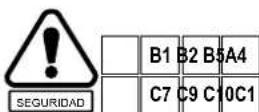
ANTES DE PONER EN MARCHA
natural_image
Illustration of a person using a belt drive down a large object, with no visible text or symbols.natural_image
Illustration of a person using a tool to measure a machine in a field, with another person standing nearby (no text or symbols present)ARRANQUE Y PARADA DEL MOTOR

ARRANQUE EN FRIOD
natural_image
Technical line drawing of a mechanical device with labeled component [1], no readable text or symbols presentnatural_image
Two line drawings of a person using a manual sewer mask, shown from different angles (no text or symbols present)CON EL CABEZAL DE HILO DE NYLON
CORTE
natural_image
Technical line drawing of a mechanical pump assembly with a rotary knob (no text or symbols)![[2] [3]](/content/2026/04/668929/images/7a6d6c362558848774069cd2521cb94fdd2ea9de6224ba75bb2878dcb8f11fb7.jpg)
natural_image
Line drawing of a person walking with a long tool, no text or symbols presentGUARDAR
natural_image
Simple line drawing of a fuel can with a fuel pump icon and cross-shaped slots (no text or symbols)Honda Motor Europe (North)
Hondastraße 1
2351 Wiener Neudorf
Tel. : +43 (0)2236 690 0
Fax : +43 (0)2236 690 480
http://www.honda.at
BALTIC STATES
(Estonia / Latvia / Lithuania)
Honda Motor Europe Ltd.
Estonian Branch
Tulika 15/17
0613 Tallinn
Tel.: 372 6801 300
Fax:372 6801 301
honda.baltic@honda-eu.com
BELGIUM
Honda Motor Europe (North)
Doornveld 180-184
1731 Zellik
Tel.:32 26 20 10 00
Fax:32 26 20 10 01
http://www.honda.be
bh pe@honda-eu.com
BULGARIA
Kirov Ltd.
49 Tsaritsa Yoana blvd
1324 Sofia
Tel. : +359 2 93 30 892
Fax: +359 2 93 30 814
http://www.kirov.net
honda@kirov.net
CROATIA
Hongoldonia d.o.o.
Jelkovecka Cesta 5
10360 Sesvete – Zagreb
M50 Business Park, Ballymount
Dublin 12
Tel. : +353 1 4381900
Fax: +353 1 4607851
http://www.hondaireland.ie
service@hondaireland.ie
ITALY
The Associated Motors
Company Ltd.
New Street in San Gwakkin Road
Honda Motor Europe (North)
Afd. Power Equipment-Capronilaan 1
1119 NN Schiphol-Rijk
Tel. : +31 20 7070000
Fax: +31 20 7070001
http://www.honda.nl
NORWAY
Berema AS
P.O. Box 454
1401 Ski
Tel. : +47 64 86 05 00
Fax: +47 64 86 05 49
http://www.berema.no
berema@berema.no
POLAND
Aries Power Equipment Sp. z o.o.
ul. Wroclawska 25
01-493 Warszawa
Tel. : +48 (22) 861 4301
Fax : +48 (22) 861 4302
http://www.ariespower.pl - www.mojahonda.pl
info@ariespower.pl
PORTUGAL
Honda Portugal, S.A.
- MKAD 47 km., Leninsky district.
Moscow region, 142784 Russia
Tel. : +7 (495) 745 20 80
Fax : +7 (495) 745 20 81
http://www.honda.co.ru
postoffice@honda.co.ru
SERBIA & MONTENEGRO
Bazis Grupa d.o.o.
Grcica Milenka 39
11000 Belgrade
Tel. : +381 11 3820 295
Fax : +381 11 3820 296
http://www.hondasrbija.co.rs
SLOVAK REPUBLIC
Honda Slovakia, spol. s r.o.
Prievozská 6 - 821 09 Bratislava
Tel.: +421 2 32131112
Fax : +421 2 32131111
http://www.honda.sk
SLOVENIA
AS Domzale Moto Center D.O.O.
Blatnica 3A
1236 Trzin
Tel.:+38615622242
Fax : +386 1 562 37 05
http://www.as-domzale-motoc.si
SPAIN & LAS PALMAS
PROVINCE
(Canary Islands)
Greens Power Products, S.L.
Avda. Ramon Ciurans, 2
08530 La Garriga - Barcelona
Tel. : +34 3 860 50 25
Fax: +34 3 871 81 80
http://www.hondaencasa.com
SWEDEN
Honda Nordic AB
Honda (UK) Power Equipment
470 London Road
Slough - Berkshire, SL3 8QY
Tel. : +44 (0)845 200 8000
http://www.honda.co.uk
EC-Declaration of Conformity
1) The undersigned, Mr Takayoshi Fukai, representing the manufacturer, herewith declares that the machinery described below complies with all the relevant provisions of the Machinery Directive 2006/42/EC, 98/37/EC. The machinery also complies with the provisions of the:
- Outdoor noise Directive: 2000/14/EC, 2005/88/EC
- EMC Directive: 2004/108/EC
2) Description of the machinery:
a) Generic denomination: Brush cutter
b) Function: Cutting of brush
c) Type:
d) Serial number:
UMK425E1 (LEET - UEET), UMK435E1 (LEET - U9ET)
| UMK425E1 | UEET | HAJF | 1010000 ~ 1025584 |
| UMK425E1 | LEET | HAHF | 1010000 ~ 1028240 |
| UMK435E1 | U9ET | HALF | 2000001 ~ 2013712 |
| UMK435E1 | LEET | HAKF | 1010000 ~ 1026064 |
3) Outdoor noise Directive
a) Measured sound power: 108 dB(A) (UMK425E1 - UMK435E1)
b) Guaranteed sound power: 109 dB(A) (UMK425E1 - UMK435E1)
c) Noise parameter:
Engine net power: 0.72 kW/7 000 min-1 (UMK425E1) 1.00 kW/7 000 min-1 (UMK435E1)
d) Conformity assessment procedure: Annex V
e) Notified body: N/A
Honda France Manufacturing S.A.S.
5) Authorized Representative able to compile the technical documentation:
N/A
6) Reference to harmonized standards
EN ISO 11806 : 2008
EN ISO 14982 : 1998
7) Other national standards or specifications
N/A
Done at: Date: President: Signature:
ORMES 01 12 2009 Takayoshi Fukai


- SAFETY INSTRUCTIONS
- WARNING :
- CAUTION:
- HOW TO IDENTIFY YOUR MACHINE
- OWNER'S MANUAL
- UMK425E1-UMK435E1
- Brushcutters
- ! WARNING :
- TRAINING
- PREPARATION
- B3. WARNING: DANGER!
- OPERATION
- MAINTENANCE AND STORAGE
- SAFETY STICKERS
- IDENTIFICATION OF MACHINE
- GENERAL DESCRIPTION
- IDENTIFICATION OF COMPONENTS
- CONTENTS OF BAG
- FITTING
- GRIPS AND HANDLES
- ATTACHMENT PROTECTORS
- UTILIZATION WITH NYLON LINE CUTTING HEAD
- UTILIZATION WITH BLADE
- ASSEMBLING THE CUTTING SYSTEM
- NYLON LINE CUTTING HEAD
- - TOOTH BLADE
- FITTING AND ADJUSTING THE HARNESS
- PRELIMINARY PREPARATION AND CHECKS
- BALANCING THE MACHINE
- CAUTION: (U type)
- FILLING THE FUEL TANK
- FUEL CONTAINING ALCOHOL
- FILLING THE OIL TANK
- ! WARNING
- CHECKING THE OIL LEVEL
- BEFORE STARTING UP
- STARTING AND STOPPING THE ENGINE
- COLD START
- START THE ENGINE AS FOLLOWS:
- HOT START
- WARNING:
- OPERATING POSITION
- WITH NYLON LINE TYPE CUTTING HEAD
- WARNING
- LINE LENGTH ADJUSTMENT
- CUTTING
- WITH 3-TOOTH AND 4-TOOTH BLADE
- MAINTENANCE
- REPLACING THE LINE
- SHARPENING
- [A] Unsatisfactory
- [B] Satisfactory
- ADJUSTING THE CARBURETOR
- PROCEDURE
- CHECKING THE SPARK PLUG
- ENGINE OIL CHANGE
- AIR CLEANER MAINTENANCE
- LUBRICATING THE TRANSMISSION HEAD
- TROUBLESHOOTING
- TRANSPORT AND STORAGE
- TRANSPORT
- STORAGE
- FOLDING THE HANDLE (U TYPE ONLY)
- USING THE AFTER A STORAGE PERIOD
- FUEL STORAGE
- NOTE:
- ACCESSORIES
- CURRENT PARTS, CONSUMABLES
- INTRODUCTION
- TABLE DES MATIÈRES
- CONTENU DU SAC
- PRÉCAUTION:
- PRÉCAUTION: (Type U)
- REMLISSAGE DU RÉSERVOIR DE CARBURANT
- ! ATTENTION :
- CONTRÔLE DU NIVEAU D'HUILE
- AVANT LA MISE EN MARCHE
- AVEC LA TÊTE À FIL DE NYLON
- AVEC UNE LAME 3/4 DENTS
- COUPE
- RÉGLAGE DU CARBURATEUR
- MÉTHODE
- REMISAGE
- INHALTSVERZEICHNIS
- AUSPACKEN
- VORSICHT:
- NYLONFADEN-MÄHKOPF
- VORSICHT: (Typ U)
- BEFÜLLEN DES KRAFTSTOFFTANKS
- GEBRAUCH MIT NYLONFADEN-MÄHKOPF
- MÄHEN
- VERGASEREINSTELLUNG
- METHODE
- INDICE
- CONTENUTO DEL SACCHETTO
- PRECAUZIONI:
- PRECAUZIONI: (Tipo U)
- TESTA CON FILO DI NYLON
- TAGLIO
- REGISTRAZIONE DEL CARBURATORE
- PROCEDURA
- DEPOSITO
- INHOUDSOPGAVE
- INHOUD VAN DE ZAK
- MONTAGE
- HANDGREPEN
- VOORZICHTIG:
- BENZINETANK VULLEN
- ! WAARSCHUWING :
- OLIEPEIL CONTROLEREN
- VOOR U DE MACHINE START
- MOTOR STARTEN
- KOUDE MOTOR STARTEN
- NYLONTRIMMERKOP GEBRUIKEN
- SNIJDEN
- CARBURATEUR NASTELLEN
- WERKWIJZE
- ACCESSOIRES
- COURANTE ONDERDELEN, VERBRUIKSPRODUCTEN
- PRECAUCIÓN:
- LLENADO DEL DEPOSITO DE GASOLINA
- ADVERTENCIA :
- ANTES DE PONER EN MARCHA
- ARRANQUE Y PARADA DEL MOTOR
- ARRANQUE EN FRIOD
- CON EL CABEZAL DE HILO DE NYLON
- CORTE
- GUARDAR
- BALTIC STATES
- BELGIUM
- BULGARIA
- CROATIA
- ITALY
- NORWAY
- POLAND
- PORTUGAL
- SERBIA & MONTENEGRO
- SLOVAK REPUBLIC
- SLOVENIA
- SPAIN & LAS PALMAS
- PROVINCE
- SWEDEN
- EC-Declaration of Conformity
- Honda France Manufacturing S.A.S.
- N/A
Brand : Honda
Model : UMK 435 UE
Category : Grass trimmer