
FÖRDELAKTIG 405.158.65 - Cooker IKEA - Free user manual and instructions
Find the device manual for free FÖRDELAKTIG 405.158.65 IKEA in PDF.

User questions about FÖRDELAKTIG 405.158.65 IKEA
0 question about this device. Answer the ones you know or ask your own.
Ask a new question about this device
Download the instructions for your Cooker in PDF format for free! Find your manual FÖRDELAKTIG 405.158.65 - IKEA and take your electronic device back in hand. On this page are published all the documents necessary for the use of your device. FÖRDELAKTIG 405.158.65 by IKEA.
USER MANUAL FÖRDELAKTIG 405.158.65 IKEA
Please refer to the last page of this manual for the full list of IKEA appointed Authorized Service Centre and relative national phone number.
| Safety information 4 | User menu customisation 23 | |
| General information 8 | Cookware guidance | 24 |
| Electrical connection 10 | Power management 25 | |
| Cleaning and maintenance 13 | Troubleshooting | 26 |
| Product description 15 | Extractor technical data | 27 |
| Indicators 15 | Extractor energy efficiency | 28 |
| Control panel 16 | Hob energy efficiency | 28 |
| Power limitation 18 | Rating plate | 29 |
| Hob functions 19 | Environmental aspects | 29 |
| Cooking table 21 | IKEA guarantee | 30 |
| Extractor functions 22 |
Safety information
For your safety and the correct operation of the device, please read this manual carefully before installation and use. Always keep these instructions with the appliance, even when it is sold or passed on to third parties. It is important that the users are well versed in the operating and safety features of the appliance. The induction system of these hobs complies with the provisions of EMC standards and the EMF directive and should not interfere with other electronic devices. Individuals with pacemakers or other electronic implants should consult their doctor and the manufacturer of the implant to assess whether these devices are sufficiently resistant to interferences.
The electrical connection must be performed by a specialised technician. Before making the electrical connection, please read the section entitled ELECTRICAL CONNECTION.
For appliances with a power supply cable, the terminals or section of wire between the cable anchor point and the terminals must be laid out so that they allow the live wire to be extracted before the earth wire if it comes loose.
ENGLISH 5
- The manufacturer cannot be held responsible for any damage resulting from incorrect or inadequate installation.
- Check that the mains power supply corresponds to the one indicated on the rating plate affixed to the inside of the product.
- The cut-out devices must be installed in the fixed system according to wiring system regulations.
- For Class I appliances, check that the domestic power supply has a suitable earthing connection.
- Connect the suction hood to the flue using a suitable pipe. Refer to the purchasable accessories indicated in the installation manual (for circular pipes: minimum diameter 120 mm). The length of the discharge piping must be as short as possible.
- Connect the product to the mains using an omnipolar switch.
- The air venting regulations must be complied with.
- Never connect the suction appliance to ducts carrying combustion fumes (heaters, fireplaces, etc.).
- If the suction hood is used alongside non-electrical appliances (e.g. appliances with gas burners), it is necessary to guarantee a sufficient level of ventilation in the room, to prevent any exhaust backflow. When the cooking appliance is used together with other appliances using non-electrical power sources, the negative pressure in the room must not exceed 4 Pa, to prevent the fumes being sucked back into the room by the cooking appliance.
- The air must not be discharged into a pipe that is also used as a flue for appliances powered by gas or other fuels.
- If the power cable is damaged, it must be replaced by the manufacturer, an authorised service centre or a qualified technician, to avoid any risk of danger.
- Connect the appliance plug to a socket that complies with current regulations and is in an accessible area.
ENGLISH 6
- As regards the technical and safety measures to be taken for exhausting of fumes, it is important that the regulations set by local authorities be followed carefully.
⚠ WARNING: Remove the protective films before installing the appliance.
- Only use the screws and other hardware elements supplied with the appliance.
⚠ WARNING: Failure to install the screws or fixing devices as described in these instructions may lead to a risk of electric shocks.
- Never look at the light directly through optical devices (binoculars, magnifying glasses, etc.).
- Cleaning and maintenance must not be carried out by children, unless they are supervised by an adult.
- Children must be supervised to ensure that they do not play with the appliance.
- This appliance must not be used by persons (including children) with limited physical, sensory or mental abilities, or by inexperienced or untrained persons, unless closely supervised and instructed in the safe use of the appliance by a person responsible for their safety.
- This appliance may be used by children over the age of eight and by persons with limited physical, sensory or mental abilities or with insufficient experience and knowledge, provided they are closely supervised and instructed on the safe use of the appliance and on the dangers that it involves. Do not allow children to play with the appliance.
⚠ WARNING: The appliance and its accessible parts become extremely hot during use.
Take great care not to touch the heating elements.
ENGLISH 7
Keep children under 8 years of age well away from the appliance, unless they are under constant supervision.
- Clean and/or replace the filters after the period indicated (danger of fire). See the paragraph on Cleaning and maintenance.
- Always guarantee adequate ventilation of the room when the appliance is used in conjunction with other appliances powered by gas or other fuels (this does not apply to appliances that only recirculate the air within the room).
⚠ WARNING: If the surface shows any signs of cracking, turn the appliance off to prevent any risk of electric shock. The appliance and its accessible parts become extremely hot during use.
- Do not turn the device on if the surface is cracked or any damage is visible in the thickness of the material.
- Do not touch the appliance if your hands or body are wet.
- Do not use steam appliances to clean the product.
- Do not rest metal objects such as knives, forks, spoons and pan lids on the surface of the hob, as they might overheat.
- Use the relevant control to turn the hob off after use; do not rely on the pan indicators.
WARNING: Unsupervised cooking on a hob using oil and grease may be dangerous and could cause a fire. NEVER attempt to put flames out with water. Turn the appliance off and suffocate the flames by covering them with a pan lid or a fire blanket, for example.
⚠ WARNING: The cooking process must be supervised. A short cooking process must be constantly monitored.
- The appliance is not designed to be started using an external timer or a separate remote-controlled system.
⚠ WARNING: Danger of fire: do not place objects on the cooking surfaces.
- The appliance must be installed to allow it to be cut off from the electrical power supply with a contact opening (3 mm) that ensures complete disconnection under overvoltage category III conditions.
- The appliance must never be exposed to the elements (rain, sun).
- Ventilation of the appliance must comply with the manufacturer's instructions.
- Keep the packaging away from children and animals.
- Kitchen hoods and other cooking fume extractors can affect the safe operation of appliances which burn gas or other fuels (including those in other rooms) due to the backflow of combustion gases. These gases can cause carbon monoxide poisoning. After installing a kitchen extractor hood or any other cooking fume extractor, make sure that the gas appliances are tested by a certified technician to guarantee that there is no backflow of combustion gases.
General information
General recommendations
- Never use abrasive sponges, wire wool, hydrochloric acid or other products that might scratch or mark the surface.
- For safety reasons, do not use steam jet or high-pressure cleaners to clean the appliance.
- Do not consume any food that falls accidentally or is deposited on the surface and on the functional or aesthetic elements of the hob.
Use
- The extractor hood has been designed solely to eliminate cooking fumes during domestic use.
- Never use the appliance for purposes other
than those for which it has been designed.
- Deep fryers must be continuously monitored during use: overheated oil could catch fire.
- Do not operate the appliance using an external timer or separate remote-controlled system.
- The appliance must never be installed behind a decorative door, to prevent it from overheating.
- Never stand on the appliance, as this may damage it.
- Do not rest hot pots and pans on the frame, as this may damage the silicone seals.
- Do not cut or prepare foodstuffs on the surface and do not drop hard objects onto
ENGLISH 9
it. Do not drag pans or plates over the surface.
Cabinet requirements
Installation
- The appliance is intended for recessed installation in the kitchen worktop above a cabinet with a width of 600 mm or more.
- If the appliance is installed on flammable materials, it is necessary to strictly comply with the guidelines and regulations regarding low voltage installations and fire protection.
- For fitted units, the components (plastic materials and veneered wood) must be assembled with heat-resistant adhesives (min. 85 °C): Unsuitable materials and adhesives can result in warping and detachment.
- The kitchen cabinet must allow sufficient room for the electrical connections of the appliance. Suspended kitchen cabinets above the appliance must be installed at a distance that provides enough room for comfortable working process.
- The use of hard wood decorative borders around the worktop behind the appliance is allowed, in this case the minimum distance remains as indicated on the installation illustrations.
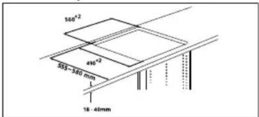
- Positioning and dimensions of the cut-out for built-in appliance is shown in the illustration below. The measurements shown are only valid if the following condition is met: worktop overhang to cabinet front is 35 mm.
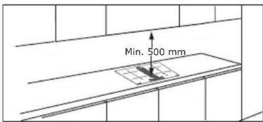
- Minimum distance between built-in appliance and any cabinet above is 500mm.
• To prevent leakage of liquid between the edge of the hob and the worktop, place the adhesive seal provided along the entire outer edge of the hob before assembly. Please refer to Assembly Instruction. Please refer to the assembly instructions.
Electrical connection
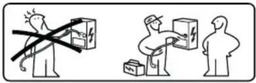
- All electrical connections must be carried out by an authorised installer.
- Follow the connection diagram (on the under side of the product).
- This appliance has a Y-type connection and requires a mains cable H05VV-F. Cable needs mandatory sleeves. According to IEC regulations use for one-phase connection: mains cable 3 × 4 ~mm^2 , for two-phase connection: mains cable 4 × 2.5 ~mm^2 and for NL connection mains cable 5 × 2.5 ~mm^2 . External cable diameter: min 8 mm - max 12 mm. Please respect specific national regulations in the first priority.
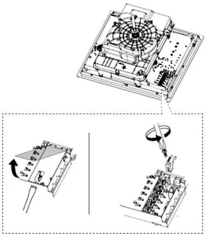
- The connection terminals can be accessed by removing the junction box cover.
- Check that the domestic power supply characteristics (voltage, maximum power and current) are compatible with those of the appliance.
- Connect the appliance as shown in the diagram (in compliance with reference standards in force nationally for mains voltage).
- Do not weld any of the cables!
Electrical connection

WARNING: All electrical connections must be carried out by an authorised installer.
- Before making the connections, check that the rated voltage of the appliance indicated on the rating plate corresponds to the mains power supply. The rating plate is affixed to the underside of the hob.
- Observe the wiring diagram (located underneath the hob).
- Only use original components supplied by the spare parts service.
• The appliance is not equipped with a net-
work cable. Purchase the correct one from a specialist dealer.
- If the cables are damaged, replace with original spare parts cables. Contact the call center of your IKEA store.

Warning! Do not weld any of the cables!
natural_image
Technical line drawing of a computer motherboard with exploded and assembled views (no text or symbols)ENGLISH 11
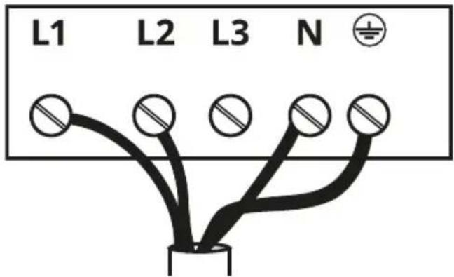
Connection diagram product side
Insert the shunts between the screws as illustrated
220V - 240V 1N \~
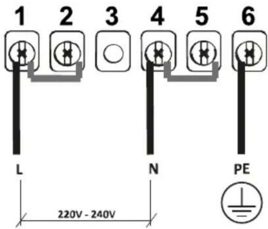
| L | Black or brown |
| N | Blue |
| Yellow / Green |
NL 220V - 240V 2N \~
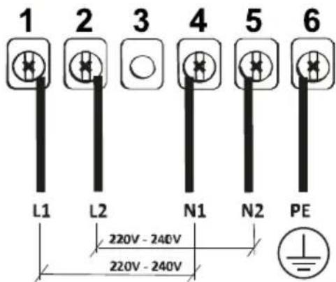
| L1 | Brown |
| L2 | Black |
| N1 | Blue |
| N2 | Blue |
| Yellow / Green |
380V - 415V 2N \~
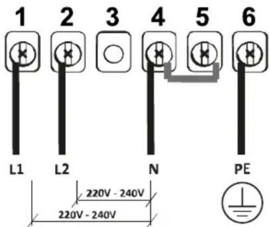
| L1 | Brown |
| L2 | Black |
| N | Blue |
| Yellow / Green |
Connection diagram home side
220V-240V 1N\~
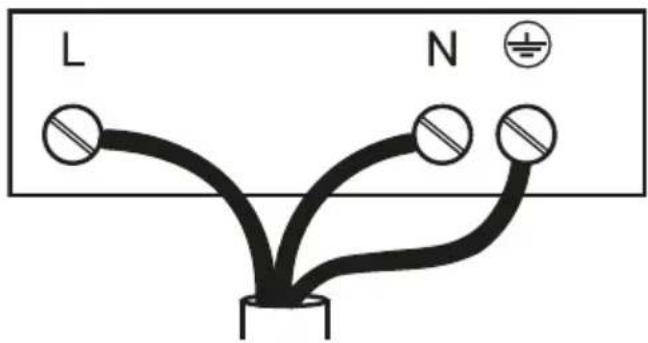
| L | Black or brown |
| N | Blue |
| Yellow / Green |
220V - 240V 2N \~

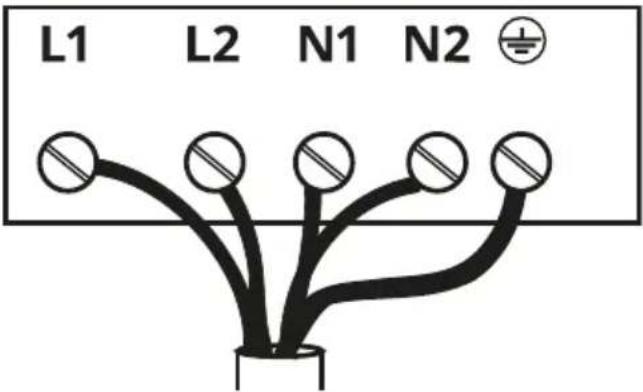
| L1 | Brown |
| L2 | Black |
| N1 | Blue |
| N2 | Blue |
| Yellow / Green |
380V - 415V 2N\~
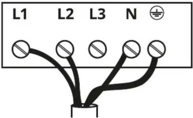
| L1 | Brown |
| L2 | Black |
| N | Blue |
| [6500] | Yellow / Green |
Cleaning and maintenance
- Switch the appliance off or disconnect it from the electricity supply before any maintenance work.
Activated charcoal filter
- The activated charcoal filter (check as-sembly instructions) can be regenerated. The activated charcoal anti-odour filter can be washed and regenerated every 3-4 months (or more frequently if the hood is used intensively), up to a maximum of 8 regeneration cycles. To order a new filter, please contact the after-sales service (see the table at the end of the manual).

Regeneration procedure
- Wash in the dishwasher at a MAX temperature of 70^ or hand wash in hot water without using abrasive sponges (do not use detergents!).
- Dry in the oven at a MAX temperature of 70^ for 2 hours (it is advisable to carefully read the user manual and the assembly instructions of the oven you own).
Cast-iron grid
- Do not wash in the dishwasher. Clean the grid with warm water and mild soap, without using abrasive sponges (do not use aggressive or abrasive detergents!).
natural_image
Isometric technical diagram of a mechanical assembly with no visible text or symbolsGrease filter
- Clean or replace the filters continuously according to below time intervals, to maintain good performance of the hood and to prevent a potential fire hazard, caused by ex-
cessive grease build-up.
- The grease filters must be cleaned every 2 months of operation, or more frequently for particularly heavy usage, and can be washed in a dishwasher.
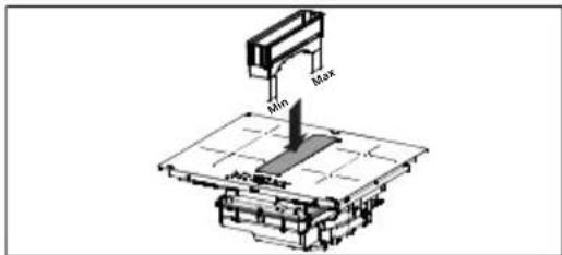
The upper overflow tray is part of the grease filter and must be inspected after every cooking cycle or every time you notice that liquid has spilled onto the hob. Wash with hot water and remove any food residue to prevent odours and deposits from forming.
Drip tray
Under normal circumstances, check and empty the drip tray every two weeks.
Remove the drawer before checking the drip tray, especially if there are large amounts of spilt liquid. Press the valve upwards and unscrew it to empty the container. The valve is replaceable and can be purchased as a spare part.
natural_image
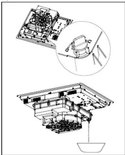
Architectural line drawings of a traditional Japanese building interior, showing structural components and structural details (no text or symbols)Cleaningthe'appliance
- Clean the appliance after every use to pre-
ENGLISH 14
vent any residual food from getting burned on it. It is much harder work to remove encrusted and burnt-on dirt.
- For day-to-day dirt, use a soft cloth or sponge and a suitable detergent. Follow the manufacturer's recommendations regarding detergents to be used. The use of protective detergents is recommended.
- Remove encrusted dirt, for example milk that has boiled over, using a scraper pad suitable for vitreous ceramic, while the hob is still hot. Follow the manufacturer's recommendations regarding scraper pads to be used.
- Remove food containing sugar, for example jam that has spilt during cooking, using a scraper pad suitable for vitreous ceramic, while the hob is still hot. If you do not, the residue may damage the vitreous ceramic surface.
- Remove any melted plastic using a scraper pad suitable for vitreous ceramic, while the cooker hob is still hot. If you do not, the residue may damage the vitreous ceramic surface.
- Remove limescale using a small amount of limescale remover solution, for example vinegar or lemon juice, once the cooker hob has cooled down. Then, clean again with a damp cloth.
Product description
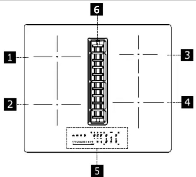
| 1 | Single cooking zone (220x197 mm) 2100 W, with 3000 W Booster function |
| 2 | Single cooking zone (220x197 mm) 2100 W, with 3000 W Booster function |
| 3 | Single cooking zone (145 mm) 1400 W, with 1850 W Booster function |
| 4 | Single cooking zone (200 mm) 2300 W, with 3000 W Booster function |
| 5 | Control panel |
| 6 | Extractor |
| 1 + 2 | Bridge cooking area |
Indicators
Pan detection
Each of the cooking zones is equipped with a system to detect the presence of a pan. The pan detection system recognises pans with a magnetisable base suitable for use with induction hobs. If the pan is removed during cooking or if an unsuitable pan is used, the display next to the bar graph with flash with the symbol.
If there are no pans placed on the cooking zone during the 10-second pan presence detection period:
- The cooking zone switches off automatically after 10 seconds.
- The display for each cooking zone will indicate
Residual heat indicator
If a cooking zone has been turned off but is still hot, the panel will still display the letter H to indicate the risk of burns.
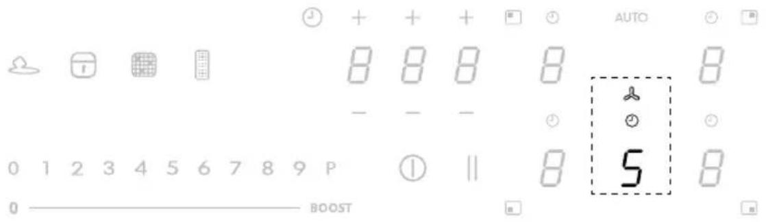
Control panel
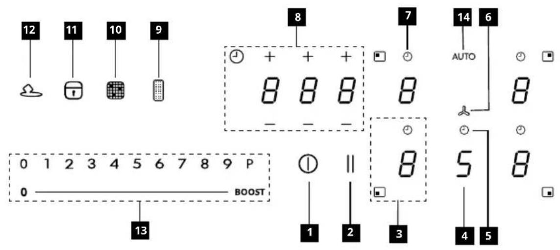
| 1 | On/Off |
| 2 | Pause key |
| 3 | Cooking zone power level indicator |
| 4 | Extractor power level indicator |
| 5 | Extractor timer control |
| 6 | Extractor controls zone symbol |
| 7 | Cooking zone timer control |
| 8 | Timer management zone |
| 9 | Grease filter saturation indicator |
| 10 | Activated carbon filter saturation indicator |
| 11 | Lock key |
| 12 | Melting |
| 13 | Scroll keypad |
| 14 | Auto key |
ENGLISH 17
The cooking zones can be activated by pressing the reference digit 8. The digit becomes brighter to confirm the operation.
When a pan is placed on one of the 4 cooking areas, the hob automatically detects its presence and lights up the corresponding digit to activate it.
If there are no pans or other objects on the hob, the digits are not visible.
The functions which can be selected are always visible on the control panel, but with a dimmed light. Select the functions by touching the corresponding symbol.
Turning the appliance on
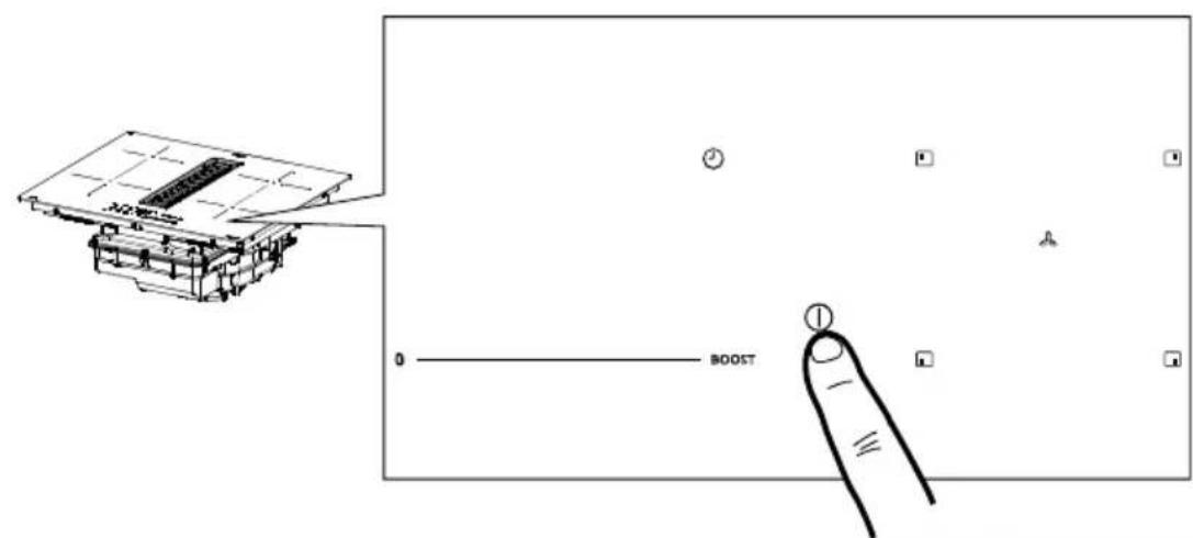
Press and hold the On/Off button for 2 seconds to turn the hob on and activate its functions.
At this point the hob is on but all the cooking zones and the hood are at zero power. The Hob will switch off automatically after 20 seconds if it is not being used.
Attention: For safety reasons, the hob can always be turned off using the On/Off button.
Attention: The functions that can be selected will always be the ones that are illuminated/visible on the control panel, and these will always be the only ones that can be activated.
The controls for the cooking zones, extractor and timer can be activated by pressing on the reference Digit.
The Digit lights up more intensely to confirm the operation.
Warnings for the' installer: Check the hob power setting and change it if necessary. See the "Power limitation" section. By default, the hob is set for an absorption power of 7.4 Kw.
Power limitation
When connecting to the household power supply for the first time, the installer must set the power of the cooking zones based on the actual capacity of the household power supply.
If this is not necessary, the hob can be turned on directly using ⚠ otherwise, follow the operations below to access the menu.
Before carrying out the procedure, it is advisable to read the entire paragraph.
Connect the hob to the domestic mains power.
- All the digits light up for a few seconds, then switch off and only keeps flashing.
- Press and hold : the digits in the cooking area indicate
- While holding down, start pressing the zone digits, proceeding anti-clockwise.

flowchart
graph TD
    A["1"] --> B["2"]
    B --> C["3"]
    C --> D["4"]
    D --> E["5"]
    E --> F["6"]
    F --> G["7"]
    G --> H["8"]
The rear left digit indicates and a number indicating the type of menu. The front left digit indicates a number which depends on the parameters indicated in the selection.
Select the digit with and press "8" in the power bar.
Select the front left digit and select the correct setting.
See the following table for the specifications:
| Value on the power bar | KW | Notes |
| 0 7.4 | Standard initial setting | |
| 1 | 6 | |
| 2 | 5 | |
| 3 | 4 | |
| 4 3.5 | ||
| 5 | 3 | |
| 6 2.5 |
Once the correct value has been entered, confirm by touching and holding Ⓘ
Hob functions
   0 1 2 3 4 5 6 7 8 9 P 0 1 2 3 4 5 6 7 8 9 P 0 1 2 3 4 5 6 7 8 9 P 0 1 2 3 4 5 6 7 8 9 P 0 1 2 3 4 5 6 7 8 9 P 0 1 2 3 4 5 6 8 9 P 0 1 2 3 4 5 6 7 8 9 P 0 1 2 3 4 5 6 8 9 P 0 1 2 3 4 5 6 7 8 9 P 0 1 2 3 4 5 6 8 9 P 0 1 2 3 4 5 6. 0 1 2 3 4 5 6 7 8 9 P 0 1 2 3 4 5 6 7 8 9 P 0 1 2 3 4 5 6 7 8 9 P 0 1 2 3 4 5 6 7 8 9 P 0 1 2 3 4 5 6 7 8 9 P 0 1 2 3 4 5 6 8 9 P 0 1 2 3 4 5 6 7 8 9 P 0 1 2 3 4 5 6 8 9 P 0 1 2 3 4 5 6 7 8 9 P 0 1 2 3 4 5 6 8 9 P 0 1 2 3 4 5 6. | ||
| Child lock | This function prevents accidental use of the appliance. This cannot be used during a cooking operation. | |
| To enable: remove all cookware from the appliance, turn the appliance off. Turn the appliance on and within 3 seconds press and hold any of the 5 digits for 3 seconds. Release and slowly swipe along the power bar from 0 to BOOST. An "L" will appear on all 5 digit displays. | ||
| To disable: turn the appliance on and then press and hold any of the 5 digits for 3 seconds. Release and slowly swipe along the power bar from BOOST to 0. The 5 digit displays will light up indicating a power level. | ||
| Lock | It is possible to lock the hob functions during use, e.g. to clean the hob. The function is enabled even if the hob is switched off and on again.If the electricity supply is cut, the function is disabled. | |
| To enable: press and hold for 1 second. | ||
| To disable: press | ||
| Boost function | Every cooking area can be set to an additional power level for a maximum of 5 minutes. | |
| To enable: select one of the 4 cooking areas and select "P" on the power bar. The corresponding digit indicates. | ||
| To disable: select one of the other possible values on the power bar. | ||
| Cooking zone timer | The timer allows a specific cooking area to be switched off when the set time expires.The cooking areas can be programmed individually because each one has its own timer. | |
| To enable: With the cooking area in operation, press to access the timer management controls for that zone.The 3 digits indicate "0 0 0". Press "+" or "-" to set the timer countdown. | ||
| Hours - Tenths - MinutesTo confirm the set time, do not touch anything for 10 seconds.When the countdown has finished, the digits are reset and an audible signal is emitted. The function can be interrupted by pressing any key.If the timer is enabled for more than one cooking area, the 3 digits will always show whichever timer is about to finish first. | ||
| To deactivate: with the cooking area in operation, press to access the timer management controls for that zone.Set the three digits to "0 0 0" using "+" or "-" or press the On/Off key. | ||
| Timer (generic) | Timer with alarm for generic use. | |
| To enable: switch on the hob making sure there are no pans or active cooking areas.The 3 digits to control the timer show “- - -”.Press the digit to access the timer menu and display “0 0 0”.Press “+” or “-” to set the timer countdown. Hours - Tenths - MinutesTo confirm the set time, do not touch anything for 10 seconds.When the countdown has finished, the digits are reset and an audible signal is emitted. The function can be interrupted by pressing any key.Repeat the steps described to change the countdown value. | ||
| To disable: switch on the hob making sure there are no pans or active cooking areas.Press the digit to access the timer menu and use “+” and “-” to set the display to “0 0 0” “-” or press the On/Off key. | ||
| Melting | To enable: select the zone where the function should apply and press | |
| To disable: select the zone where the function is currently applied to and either select any other power level or press | ||
| Heating function | This function is used to heat a pan to the maximum power before continuing to cook at a selected level. The time interval for which the cooking zone is held at maximum power depends on the final cooking level that has been set. See the table: | |
| Power level Timer (seconds) | ||
| 1 | 48 | |
| 2 144 | ||
| 3 230 | ||
| 4 312 | ||
| 5 408 | ||
| 6 120 | ||
| 7 168 | ||
| 8 216 | ||
| 9 Not available | ||
| P Not available | ||
| To enable, with a pan on the hob and the cooking zone selected, press and hold the selected value (from 1 to 8) on the power bar for 3 seconds. The display of the corresponding cooking zone indicates “A”.The cooking level can be increased, but the function is disabled if it is decreased.It can also be disabled by touching and holding down the key of the cooking zone in question for 3 seconds. | ||
| Pause function | This function allows you to pause/restart any active function on the hob, by reducing the power available in the cooking zone and resetting all the functions. If the Pause function is not disabled with 10 minutes, the hob automatically switches off. | |
| To enable: With a pan on the hob and the cooking zone selected, press and hold the Pause function key for at least 1 second. All the displays indicated. | ||
| To disable: press and hold for 1 second until it starts flashing. Press any other key within 10 seconds. The function is disabled and the hob continues with the previous settings. | ||
| Recall function | This function is used to recall the function settings of the hob if it is switched off by mistake or the electricity is unexpectedly cut off. | |
| When the hob is switched off, if it is switched on again with 6 seconds by touching, the key flashes for 6 seconds. Press the key to recall the functions set previously. A beep is emitted to confirm the operation. | ||
| Combo mode (“bridge” function) | This function allows 2 cooking areas to be combined to use and control them as if they were one and have a bigger cooking area at your disposal. This function allows you to use pans with a wider base. Only the cooking zones on the left can be selected for use with this function. | |
| To enable/disable: press the digits of the left-hand or right-hand cooking zones at the same time to select the 2 areas be combined until the digit appears to show that the function has been enabled. The other digit is used to set the power level. | ||
| AUTO function “A” | The standard setting when the hob/suction hood is switched on is for the hood to start up in automatic mode with the LED “A” brightly lit. The Hood comes into operation if the power in the cooking areas is greater than “1”.It is deactivated by pressing the LED “A” which changes intensity from bright to dim in confirmation. It can also be deactivated by pressing a value, higher than “1”, on the power bar, which is confirmed by the fact that the LED “A” changes intensity from bright to dim.It is reactivated by pressing the LED “A” which changes to brightly lit. | |
Cooking table
| Power level | Cooking method To be used for | |
| 1 | Melting, heating gently Butter, chocolate, gelatine, sauces | |
| 2 | Melting, heating gently Butter, chocolate, gelatine, sauces | |
| 3 | Warming up Rice | |
| 4 | Prolonged cooking, thickening, stewing Vegetables, potatoes, sauces, fruit, fish | |
| 5 | Prolonged cooking, thickening, stewing Vegetables, potatoes, sauces, fruit, fish | |
| 6 | Prolonged cooking, braising Pasta, soups, braised meat | |
| 7 | Light frying | Rösti (potato fry-ups), omelettes, breaded and fried foods, sausages |
| 8 | Frying, deep fat frying Meat, chips | |
| 9 | Quick frying at high temperature Steak | |
| P | Quick heating Boiling water |
Extractor functions
 | |
| The controls for the cooking zones, extractor and timer can be activated by pressing on the reference Digit. | |
| “9” | Press “9” on the power bar to set INTENSIVE 1 speed. This setting is timed to operate for 10 minutes. Once this time has passed, the system will automatically return to the speed set previously. It is deactivated by selecting different speed. |
| “P” | Press “9” on the power bar twice to set INTENSIVE 2 speed. This setting is timed to operate for 5 minutes. Once this time has passed, the system will automatically return to the speed set previously. It is deactivated by selecting a different speed. |
| Function Delay | This function is only available if Automatic mode is deactivated. Automatic mode is deactivated by pressing “A Press the suction hood Digit and set a speed on the power bar.Press the Timer management Digit, which was displaying “CL” but will change to the countdown. This is pre-set to 15 minutes. |
| [84-85] | Timer symbolAfter selecting the suction hood Digit, press the Timer Management Digit to set the countdown. |
| [64-73] | Grease filter maintenance symbolThe grease filter cleaning signal is displayed by LED and it is always enabled. |
| [66-82] | Charcoal filter maintenance symbolThe hood is set by default to ducting mode. With no loads on, press the Hood controls digit to enable the suction hood. Then press and set a value on any one of the cooking areas. Press the Digit on the Hood controls digit again for 5 seconds to:Activate the charcoal filter:The charcoal (odour) filter symbol lights up for 1 second.Deactivate the charcoal filter:The charcoal (odour) filter symbol flashes twice.After activation, the icon will light up to indicate that maintenance must be carried out on the charcoal (anti- odour) filter.Reset and reactivation of the charcoal filterAfter having carried out maintenance on the filter:press and hold the key for 5 seconds. - The LED of the grease filter will turn off and the countdown will restart press and hold the key for 5 seconds. - The LED of the anti-odour filter will turn off and the countdown will restart. |
User menu customisation
Before carrying out the procedure, it is advisable to read the entire paragraph.
- Press. ①
- Press and hold again for 3 seconds.
- The key starts flashing.
- Press and hold : the digits in the cooking area indicate .
- Hold and start pressing the digit of the cooking areas in clockwise order starting from the left front one.
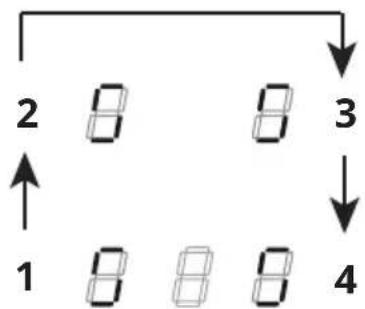
flowchart
graph TD
    A["1"] --> B["2"]
    B --> C["3"]
    C --> D["4"]
    style A fill:#f9f,stroke:#333
    style B fill:#ccf,stroke:#333
    style C fill:#cfc,stroke:#333
    style D fill:#fcc,stroke:#333
The rear left digit alternately indicates and a number from 2 to 7 indicating the menu code.
The front left digit indicates a number which depends on the parameters indicated in the selection.
- Press the left rear digit.
- Select a number on the power bar to access the menu code.
- Press the left front digit.
- Select a number on the power bar to select a value.
See the following table for the specifications:
| Menu code | Description Value | |
| U2 | Key sound volume control menu. | 0 - Sound disabled1 - Min.3 - Max. |
| U3 | Countdown beeper volume control menu. | 0 - Sound disabled1 - Min.3 - Max. |
| U4 | Display brightness level control menu. | 0 - Max.9 - Min. |
| U5 | Countdown display control menu. | 0 - Countdown display disabled1 - Countdown display enabled |
| U6 | Pan detection menu. | 0 - Disabled1 - Enabled |
| U7 | Countdown end management menu. | 0 - Continuous flashing and shut-down1 - Ten flashes and shut-down2 - One flash and shut-down |
| - Once the correct value has been entered, confirm by touching and holding for 2 seconds.- To exit the menu without saving, press .If no operation is carried out the user menu will close after 1 minute. | ||
Cookware guidance
Which pans to use
Only use pots and pans with the bottom made from ferromagnetic material which are suitable for use with inductions hobs:
- cast iron
- enamelled steel
- carbon steel
• stainless steel (including partial) - aluminium with ferromagnetic coating or ferromagnetic plate
To determine if a pot or pan is suitable, check
for the symbol (usually stamped on the bottom). You can also hold a magnet to the bottom. If it clings to the underside, the pan can be used on an induction hob.
To ensure optimum efficiency, always use pots and pans with a flat bottom that distributes the heat evenly. If the bottom is not perfectly flat, this will affect power and heat conduction.
How to use
Minimum diameter of pot/pan base for the different cooking areas.
To ensure that the hob functions properly, the pan must cover one or more of the reference points indicated on the surface of the hob, and must be of a suitable minimum diameter.
Always use the hob that best corresponds to the diameter of the bottom of the pan.
| Cooking areas | Pan base diameter | |
| ∅ min.(recommended) | ∅ max (recommended) | |
| Combined left 1 | 90 mm 230 mm | |
| Single left 110 | mm 190 mm | |
| Single front right | 110 mm 200 | mm |
| Single rear right | 110 mm 145 mm | |
Empty pots/pans or with thin base
Do not use empty or thin-based pots/pans on the hob as it will be unable to detect the temperature or turn off automatically if the temperature is too high, thus damaging the pan or the hob surface.
If this occurs, do not touch anything and wait for all components to cool down.
If an error message appears, refer to "Troubleshooting".
Normal working noises in the hob
Induction technology is based on the creation of electromagnetic fields. These electromagnetic fields generate heat directly on the bottom of the pan. Pots and pans may produce a variety of noises or vibrations, according to their construction.
These types of noise can be described as follows:
Light buzz (like the noise made by a transformer)
This noise is produced when cooking with a high level of heat, and it is determined by the amount of energy transferred by the hob to the pans. The noise will stop or decrease when the heat level is reduced.
Light whistle
This noise is produced when the pot or pan is empty, and stops as soon as it is filled with water or food.
Crackle
This noise occurs with pans made from layers of numerous different materials, and is caused by vibration of the surfaces where the different materials meet. The noise comes from the pans, and may vary according to the quantity of food and preparation method being used.
ENGLISH 25
Loud whistle
This noise occurs with pans made up of layers of different materials, and also when these are used at maximum level and on two cooking areas. The noise will stop or decrease when the heat level is reduced.
Fan noises
For the electronic system to operate correctly, the temperature of the cooker hob must be regulated. To do this, the hob is equipped with a cooling fan that is activated to reduce and regulate the temperature in the
electronic system. The fan may continue to operate after the appliance has been turned off, if the temperature of the cooker hob is still detected to be too high.
Rhythmic sounds like a clock ticking
This noise only occurs when at least three cooking areas are operating, and it disappears or decreases when some of them are turned off.
The noises described are a normal feature of induction technology and are not to be considered as defects.
Power management
This product has an electronically controlled power management function.
This function controls the delivery of the maximum power of 3700 W between the combined cooking areas (left and right side), optimising the power distribution and avoiding system overload situations.
The function distributes the maximum power available between the cooking areas used in combi mode. See the illustration. The function reduces the power of the other cooking area working in combi mode, if necessary (the highest priority is assigned to the last command).
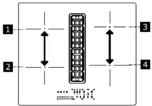
Example:
If boost level (P) is selected for hob 1, hob 2 cannot exceed level 9 at the same time and will be automatically limited.
Troubleshooting
| Error code | Description Possible causes of the error Solution | |||
| “Acoustic signal upon ignition. No error code displayed” | The hood command does not work | LIN cable damaged or badly connected to the hood electronic board | Check the connection. If the error persists, contact the After-Sales Service. | |
| ER03 | Hob switches off after 10 sec. | Continuous key activation detected.Water or pan placed on the control panel. | Remove water or pan from the ceramic glass surface and control panel. | |
| ER21 | Hob switches off. | The internal temperature of electronic parts is too high. | Let the hob cool down.Please check if the hob has sufficient ventilation.If the error persists, please contact the After-Sales Service. | |
| E2 | Corresponding cooking area switches off. | Empty or unsuitable pan.Pan or ceramic glass surface temperature too high.Electronic component temperature too high. | Let the hob cool down.Use a suitable pan.Do not heat empty pans. | |
| E3 | Corresponding cooking area switches off. | Unsuitable pan.The pan is losing its magnetic properties and may damage the induction hob. | Use a suitable pan.The error is automatically cancelled after 8 seconds and the cooking area can be used again.If any other errors occur, the pan must be changed.If the error persists, please contact the After-Sales Service. | |
| E6 | Hob does not switch on. | Power supply voltage and/or frequency is out of range. | Check mains voltage and/or frequency.If necessary, contact the After-Sales Service. | |
| E8 | Cooking areas are turned off. | Fan fault.Fan blocked by dust or fibres. | Clean and remove foreign bodies from the fan.If the error persists, please contact the After-Sales Service. | |
| E4 / E5 / E7 / E9 / ER20 / ER22 / ER31 / ER36 / ER42 / ER47 / EA / EH | Disconnect the hob from the power supply.Wait a few seconds, then reconnect the hob to the power supply.If the problem persists, call the After Sales Service and specify the error code that appears on the display. | |||
| Fan not working Cable fan unplugged Plug the cable | ||||
| Hood not working Hood power cable disconnected | Reconnect the hood power cable found towards the front right underneath the hob. | |||
If there is a fault try to solve the problem by following the troubleshooting guidelines. If the problem cannot be solved contact the After-Sales Service. You can find a full list of IKEA appointed contacts at the end of this user manual.
If you operate the appliance incorrectly, or the installation was not carried out by an authorised installer, the visit from the After-
Sales Service technician or dealer will not be free of charge, even during the warranty period.
Maintenance and repair
- Make sure that maintenance on electrical components is only carried out by the manufacturer or by the service technicians.
- Make sure that damaged cables are only replaced by the manufacturer or by the service technicians.
ENGLISH 27
When contacting the service department, please provide the following information:
- Type of fault
• Device model (Art./Cod.) - Serial number (S.N.)
This information can be found on the identification plate. The identification plate is affixed to the bottom of the device.
Technical data
Product identification
Type: 4300
Model: FÖRDELAKTIG 405.158.65
Please see the identification plate affixed to the bottom of the product.
The manufacturer makes continual improvements to products. For this reason, the text and illustrations in these instructions for use may change without warning.
Further information on the technical data is available on the website: www.Ikea.com
Extractor technical data
| Type of product | RECESSED | ||
| Width | mm 600 | ||
| Dimensions Depth | mm 520 | ||
| Min/max height | mm 906 | ||
| Max air flow* - Output | m3/h 500 | ||
| Max noise level* - Output | dBA 66 | ||
| Max air flow* - Recirculation | m3/h 370 | ||
| Max noise level* - Recirculation | dBA 71 | ||
| Extractor rated power | W 220 | ||
| Hob rated power | W 7400 | ||
| Total maximum power | W 7620 | ||
* Maximum speed (excluding Boost).
| Power supply voltage/frequency | 220-240 V, 50 Hz;220 V, 60 Hz 2N~ 380-415 V, 50 Hz;2N~ 380 V, 60 Hz |
| Weight of appliance | 14.3 Kg |
CE This appliance has been designed, manufactured and sold in compliance with EEC Directives.
The technical data are indicated on the rating plate affixed inside the appliance.
Extractor energy efficiency
| Product information according to EU regulation No. 66/2014 | Unit Value | |
| Model id | FÖRDELAKTIG405.158.65 | |
| Annual energy consumption | kWh/a 40.9 | |
| Time increase factor | 0.8 | |
| Fluid dynamics efficiency | 33.1 | |
| Energy efficiency index | 44.3 | |
| Air flow measured at the optimum efficiency point | m3/h 348 | |
| Air pressure measured at the optimum efficiency point | Pa 517 | |
| Maximum air flow | m3/h 630 | |
| Electrical power supply measured at the optimum efficiency point | W 133 | |
| Currency consumption measured in standby | W N/A | |
| Currency consumption measured when off | W 0.49 | |
| Maximum sound level (without booster setting) | dBA 66 |
Hob energy efficiency
| Product information according to EU regulation No. 66/2014 | Value |
| Model id | FÖRDELAKTIG405.158.65 |
| Hob type | Built-In Hob |
| Number of cooking areas | 4 |
| Cooking technology | Induction |
| Diameter of left cooking area (dimensions) | 220 x 185 mm |
| Diameter of right front cooking area (dimensions) | 200 mm |
| Diameter of right rear cooking area (dimensions) | 145 mm |
| Energy consumption for left cooking area (electric cooking) | 192 Wh/kg |
| Energy consumption for front right cooking area (electric cooking) | 185 Wh/kg |
| Energy consumption for rear right cooking area (electric cooking) | 181 Wh/kg |
| Energy consumption for hob (electric cooking) | 186 Wh/kg |
Reference standards:
| EN/IEC 61591 EN/IEC 60704-1 | |
| EN/IEC 60704-2-13 EN/IEC 60704-3 | |
| EN 50564 EN 60350-2 | |
Energy saving
The appliance includes features which help to save energy during cooking every day.
Rating plate
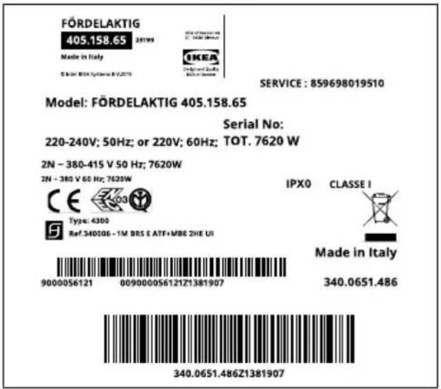
The image above shows the rating plate for the appliance.
The serial number is specific for each product.
Environmental aspects
Information on disposal
Your obligations as an end-user

This electrical or electronic equipment is worked with a crossed-out wheeled bin. The equipment may therefore only be collected and returned separately from unsorted municipal waste, i.e. it must not be disposed with household waste. The equipment can be returned, for example, to a municipal election point or, if applicable, to a tributor (see below for their take-back obligations in Germany). This also applies to components, subassemblies and consumables of the old equipment to be disposed of.
Before the old equipment may be disposed of all old batteries and old accumulators that are not enclosed by the old equipment must be separated from the old equipment. The same applies to lamps that can be removed from the old equipment without destroying them. The end-user is also responsible for deleting personal data from the old equipment.
Notes on recycling
Disposal of packaging materials
Help recycle all materials marked with this symbol. Do not dispose of such materials, especially packaging, in the household waste but via the relevant containers provided or the appropriate local collection systems.
Help to protect the environment and human health by recycling including waste of electrical and electronic appliances.
The following additional information applies in Germany
Take-back obligations of distributors
Anyone who sells electrical and electronic equipment on a sales floor area of at least 400m^2 or otherwise supplies it to end users on a commercial basis is obliged, when supplying a new equipment, to take back at the place of supply or in the immediate vicinity thereof free of charge an old equipment belonging to the end user of the same type of equipment which fulfils essentially the same functions as the new equipment. This also applies to distributors of
ENGLISH 30
groceries with a total sales area of at least 800 m ^2 who offer electrical and electronic equipment several times a calendar year or on a permanent basis and make it available on the market. In addition, such distributors must, at the request of the end-user, take back in the retail shop or in the immediate vicinity free of charge old equipment that does not exceed 25 cm in any external dimension (small electrical equipment) thereof; in this case, take-back may not be linked to the purchase of an electrical or electronic equipment but may be limited to three old equipment per type of equipment.
The place of delivery is also the private household if the new electrical or electronic equipment is de-livered; in this case the collection of the old equipment is free of charge for the end user.
The above obligations also apply to distribution using means of distance communication if the distributors maintain storage and dispatch areas for electrical and electronic equipment or total storage and dispatch areas for groceries that correspond to the sales areas mentioned above. However, the free collection of electrical and electronic equipment is then restricted to heat transmitters (e.g. refrigerators), screens, monitors and equipment containing screens with a surface area of more than 100 cm^2 and equipment where at least one of the external dimensions is more than 50 cm. For all other electrical and electronic equipment the distributor must ensure appropriate return facilities within a reasonable distance from the respective end-user; this also applies to small electrical equipment (see above) that the end-user wishes to return without purchasing a new equipment.
Energy saving
You can save energy during everyday cooking if you follow hints outlined below.
- When you heat water, only use the quantity you require.
- If it is possible, always put the lids on the cookware.
- Place the pan on the hob before you switch it on.
- Put smaller pans on the smaller cooking areas.
- Put the pans directly in the centre of the cooking area.
- Use residual heat to keep the food warm or melt it.
IKEA guarantee
How long is the IKEA warranty valid for?
This warranty is valid for five (5) years from the original purchase date of the appliance from IKEA. The original receipt is essential as a proof of purchase. Any repairs carried out under warranty do not extend the warranty period for the appliance.
Who provides support?
Customer support will be provided by the service provider appointed by IKEA through its organisation or network of authorised service partners.
What does the warranty cover?
The warranty covers any defects linked to the materials or manufacture of the household appliance and is valid from the purchase date of the household appliance at an IKEA store. The warranty is only valid on household appliances intended for household use. The exceptions are outlined under “What doesn’t the warranty cover”. In the period covered by the warranty, the repair costs (spare parts, labour and travel costs of the technical personnel) will be borne by the support service, provided that access to the appliance to perform the repair work does not entail
ENGLISH 31
unforeseen expenses. These conditions comply with the EU directive (No. 99/44/EC) and the applicable local legal provisions. The parts replaced will become the property of IKEA.
How will IKEA intervene to solve the problem?
The service provider, appointed by IKEA, will examine the product and decide, at its sole discretion, whether it is covered by the warranty. If so, the IKEA service provider or its authorised service partner, through its service centres, will, at its sole discretion, either repair the defective product or replace it with a product of the same or equal value.
What doesn't the warranty cover?
- Normal wear.
- Deliberate damage or due to negligence, damage caused by failure to follow the operating instructions, improper installation or connection to the incorrect voltage, damage caused by chemical or electrochemical reactions, rust, corrosion or water damage, including but not limited to damage caused by excessive limescale in the water pipes, and damage caused by weather and natural events.
- Parts subject to wear, e.g. batteries and light bulbs.
- Decorative and non-functional parts which do not affect normal use of the appliance, including scratches and changes in colour.
- Accidental damage caused by substances or foreign bodies and cleaning or releasing filters, drainage systems or detergent drawers.
- Damage to parts such as ceramic hobs, accessories, crockery and cutlery baskets, inlet and outlet pipes, gaskets, bulbs and their covers, screens, knobs, covers and parts of covers, unless it can be demonstrated that said damage was caused by manufacturing defects.
- Cases in which no defects are found during the technician call-out.
• Repairs not carried out by the IKEA-appointed service provider or by an authorised
service partner, or repairs where non-original parts have been used.
- Repairs caused by improper installation or installation that does not comply with the specifications.
- Use of the household appliance in non-household settings, e.g. for professional use.
- Damage due to transportation. If the customer transports the appliance to his/her home or to another address, IKEA cannot be held responsible for any damage which occurs during transportation. However, if transportation to the customer's address is carried out by IKEA, any damage due to transportation will be covered by this warranty.
- Cost of initial installation of the IKEA appliance. If an IKEA-appointed service provider or its authorised service partner repairs or replaces the equipment under the warranty, in any case the supplier or authorised service partner must also reinstall the repaired appliance or the replacement appliance, where necessary.
These limitations do not apply to work carried out properly by qualified personnel and using original parts to adapt the appliance to the safety standards of another EU country.
Applicability of national laws
The IKEA warranty gives the customer specific legal rights in addition to the statutory rights that vary from country to country. These conditions do not, however, in any way limit the consumer's rights outlined in the local legislation.
Area of validity
For household appliances purchased in an EU country and transferred to another EU country, the services will be provided under the warranty conditions which apply in the new country. The obligation to provide the service under the terms of the warranty only exists if the appliance is compliant and installed in accordance with the:
- technical specifications of the country in which the application of the warranty is re-
ENGLISH 32
quested;
- safety information outlined in the user manual.
After-sales service for IKEA appliances:
Do not hesitate to contact the IKEA after-sales service to:
- request support under the warranty;
-
ask for clarification on the installation of IKEA appliances in specific IKEA kitchen cabinets. The service will not provide support or clarifications about:
• the installation of complete IKEA kitchens;
• electrical connections (if the appliance is supplied without cables and plugs), hydraulic connections and connections to the gas supply that must be carried out by an authorised service technician. -
ask for clarification on the contents of the user manual and specifications of the IKEA appliance.
To ensure the best possible assistance, please read the assembly instructions and/or user manual carefully before contacting us.
How to contact us if you need our intervention
Consult the complete list of IKEA service providers and relevant local phone numbers on the last page of this manual.
Important! To ensure faster service, we recommend that you use the telephone numbers listed at the end of this manual. To request support, always refer to the specific appliance codes indicated in this manual. Before contacting us, make sure you know the IKEA product code (8 digits) of the appliance for which you are requesting support.
Important! KEEP THE RECEIPT!
It is your proof of purchase and it must be produced to allow you to make use of the warranty. The receipt also indicates the name and code (8-digit) of each IKEA appliance you have purchased.
Do you need any more help?
For any other questions not related to the after-sales service on the appliance, please contact the nearest IKEA store. Please read the documentation about the appliance carefully before contacting us.
Inhalt

natural_image
Technical line drawing of a mechanical device with exploded and assembled views (no text or symbols)DEUTSCH 41
natural_image
Technical diagram of a mechanical assembly with no visible text or symbolsFettfilter
natural_image
Architectural line drawing of a building interior with structural components and an inset close-up of a mechanical component (no text or symbols)Reinigungdes Geräts

natural_image
Technical line drawing of a mechanical assembly with three views: top shows internal components, middle shows a rotating component, and bottom shows a close-up of the housing (no text or symbols)FRANÇAIS 73
| L1 | Marron |
| L2 | Noir |
| N1 | Bleu |
| N2 | Bleu |
| Jaune / Vert |
380V - 415V 2N\~
| L1 | Marron |
| L2 | Noir |
| N | Bleu |
 | Jaune / Vert |
natural_image
Technical diagram of a mechanical assembly with no visible text or symbolsFiltre à graisse
natural_image
Architectural line drawing of a building interior with structural components and an inset close-up of a mechanical component (no text or symbols)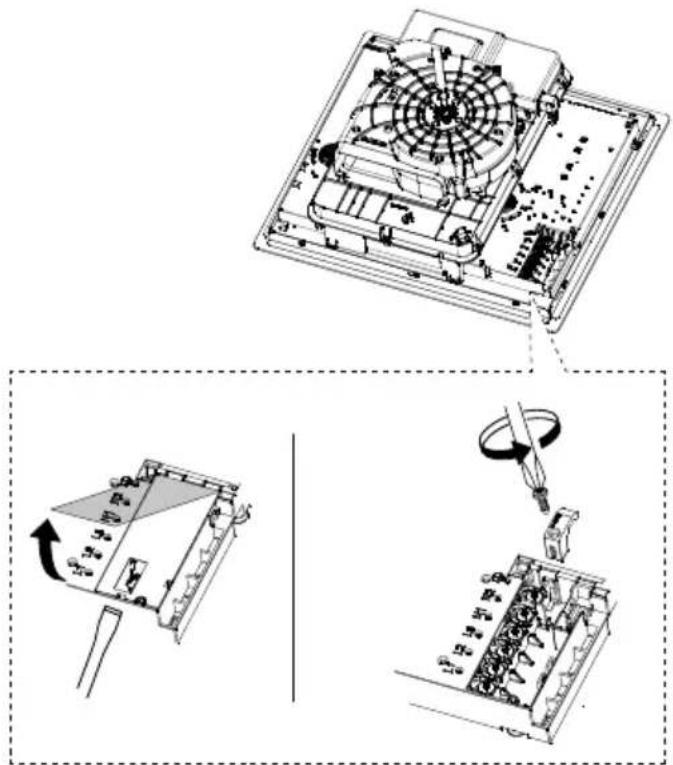
natural_image
Technical line drawing of a device's internal components and assembly, showing exploded and assembled views (no text or symbols)ITALIANO 103
| L1 | Marrone |
| L2 | Nero |
| N1 | Blu |
| N2 | Blu |
| Giallo / Verde |
380V - 415V 2N\~

| L1 | Marrone |
| L2 | Nero |
| N | Blu |
| Giallo / Verde |
natural_image
3D diagram of a mechanical assembly with a central component and an upward arrow, no visible text or symbolsFiltro antigrasso
natural_image
Architectural line drawing of a building interior with structural components and an inset close-up of a mechanical component (no text or symbols)
- Safety information
- ENGLISH 5
- ENGLISH 6
- ENGLISH 7
- General information
- General recommendations
- Use
- ENGLISH 9
- Cabinet requirements
- Installation
- Electrical connection
- ENGLISH 11
- Connection diagram product side
- Cleaning and maintenance
- Activated charcoal filter
- Regeneration procedure
- Cast-iron grid
- Grease filter
- Drip tray
- Cleaningthe'appliance
- ENGLISH 14
- Product description
- Indicators
- Pan detection
- Residual heat indicator
- ENGLISH 17
- Power limitation
- Extractor functions
- User menu customisation
- Cookware guidance
- Which pans to use
- How to use
- Empty pots/pans or with thin base
- Normal working noises in the hob
- Light buzz (like the noise made by a transformer)
- Light whistle
- Crackle
- ENGLISH 25
- Loud whistle
- Fan noises
- Rhythmic sounds like a clock ticking
- Power management
- Maintenance and repair
- ENGLISH 27
- Technical data
- Product identification
- Energy saving
- Rating plate
- Environmental aspects
- Information on disposal
- Your obligations as an end-user
- Notes on recycling
- Disposal of packaging materials
- Take-back obligations of distributors
- ENGLISH 30
- IKEA guarantee
- How long is the IKEA warranty valid for?
- Who provides support?
- What does the warranty cover?
- ENGLISH 31
- How will IKEA intervene to solve the problem?
- What doesn't the warranty cover?
- Applicability of national laws
- Area of validity
- ENGLISH 32
- After-sales service for IKEA appliances:
- Important! KEEP THE RECEIPT!
- Do you need any more help?
- DEUTSCH 41
- Fettfilter
- Reinigungdes Geräts
- FRANÇAIS 73
- Filtre à graisse
- ITALIANO 103
- Filtro antigrasso
Brand : IKEA
Model : FÖRDELAKTIG 405.158.65
Category : Cooker