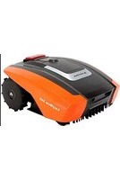
SA900B - Robot mower Yard Force - Free user manual and instructions
Find the device manual for free SA900B Yard Force in PDF.

| Product type | Robotic lawn mower |
| Brand | Yard Force |
| Model | SA900B |
| Maximum cutting area | 900 m² |
| Battery | Lithium-Ion 28 V, 2.9 Ah, 79.8 Wh |
| Power supply | Transformer FY3201500S1/S2/S3, input 100-240 V AC, 50/60 Hz, output 32 V DC, 1.5 A |
| Cutting time after charge | 60 minutes |
| Charging time | 60 minutes |
| Cutting width | 18 cm |
| Cutting height | 20 - 60 mm (5 positions) |
| No-load cutting speed | 3500 min⁻¹ |
| Robot weight | 8.5 kg |
| Charging station weight | 2 kg |
| Protection rating (robot) | IP24 |
| Protection rating (station) | IP67, IP44 plug |
| Sound power level | 64 dB(A) (K=3 dB) |
| Sound pressure level | 53 dB(A) (K=3 dB) |
| Boundary wire included | 160 m (max length 300 m) |
| Signal setting | S1 or S2 (avoids interference) |
| Functions | Auto return to station, daily programming (4 to 10 h), edge mowing, rain sensor, anti-theft alarm |
| Blades | 3 double-edged blades (ref. 846210) |
| Max slope | 40 % |
| Maintenance | Regular cleaning, turning/replacing blades, replaceable battery |
| Safety | STOP button, main switch, handle with safety switches, lightning protection |
| Transport | Rear handle, turn off before lifting |
Frequently Asked Questions - SA900B Yard Force
User questions about SA900B Yard Force
0 question about this device. Answer the ones you know or ask your own.
Ask a new question about this device
Download the instructions for your Robot mower in PDF format for free! Find your manual SA900B - Yard Force and take your electronic device back in hand. On this page are published all the documents necessary for the use of your device. SA900B by Yard Force.
USER MANUAL SA900B Yard Force
Original Instructions
FR ROBOT-TONDEUSE
Notice originale
DE MÄHROBOTER
natural_image
Black and white photo of a small robotic lawn mower (no visible text or symbols)
CE - UK CA
Read this manual carefully prior to assembling and operating the Robotic Mower. It is dangerous to operate this product without being familiar with these instructions. Keep this manual in a safe place and have it ready for future reference.
YARD FORCE
SA900B Original Instructions
CONTENT
Introduction 05
Intended purpose 05
General description 05
Technical Data 07
Safety precautions 08
Assembly instructions 2B
Operation 42
Cleaning/maintenance 48
Troubleshooting 53
Declaration of conformity 55
INTRODUCTION
Congratulations on the purchase of your new machine. During production, this device has been checked for quality and subject to a final inspection. The functionality of your equipment is therefore guaranteed. It cannot be ruled out that residual quantities of water or lubricants will remain on or in the equipment/hose lines in isolated cases. This is not a fault or defect and it represents no cause for concern.

The operating instructions constitute part of this product. They contain important information on safety, use and disposal.
Before using the product, familiarise yourself with all of the operating and safety instructions. Use the product only as described and for the applications specified. Keep this manual in a safe place and in the event that the product is passed on, hand over all documents to the third party.
The Robotic Mower is exclusively designed for mowing lawns. It is only intended for private use and is not suitable for commercial use.
INTENDED PURPOSE
Any other use that is not specifically approved in these instructions can result in damage to the Robotic Mower and could be a serious danger to the user.
This appliance MUST NOT be used by children and persons with reduced physical, sensory or mental capabilities or lack of experience and knowledge, unless they have been given supervision or instruction concerning use of the appliance by a person responsible for their safety.
Children should be supervised to ensure that they do not play with the appliance.
The owner or operator is responsible for accidents or harm to other people and their property. The manufacturer cannot be held liable for damage caused by incorrect operation of the Robotic Mower or if it is not used in line with its intended purpose.
GENERAL DESCRIPTION
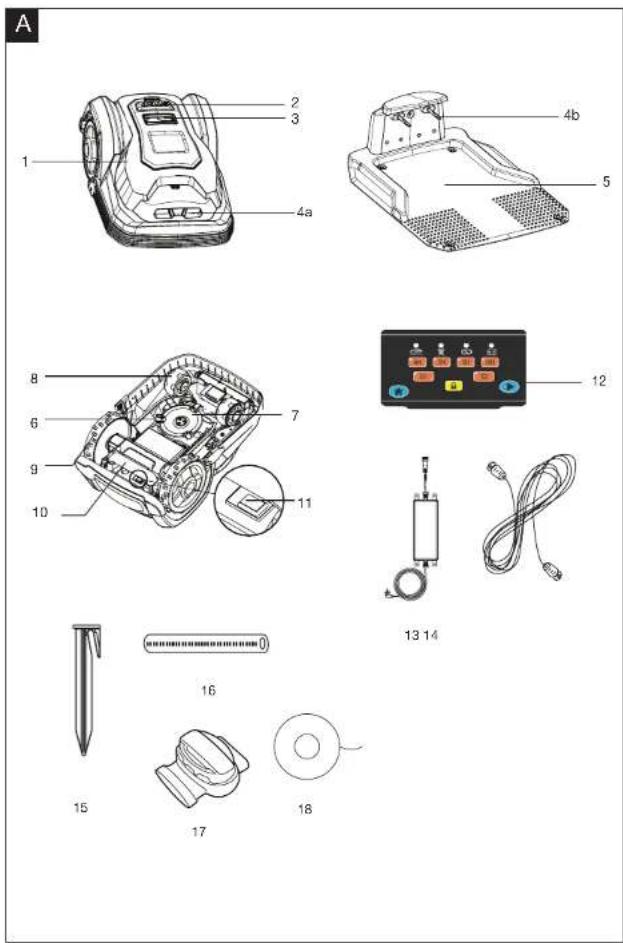
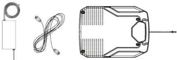
Scope of delivery
Carefully unpack the mower and check that all the subsequently listed parts are present:
- Robotic Mower
- Docking station
• Switching power supply - Extension cord
• Boundary wire
• Boundary wire connector B (blue) - Fixing pegs
- Spare blades
• Measurement ruler (on the color box) - Manual
GENERAL DESCRIPTION
Overview

The illustration of the principal functioning parts can be found on the front and back foldout pages.
1 Robotic Mower x 1
2 STOP button
3 Display and keypad
4a: Charging contacts (Robotic Mower)
4b: Charging contacts (docking station)
5 Docking station x
6 Blade (3 of each)
7 Blade disc
8 Front wheel
9 Rear wheel
10 Carry handle
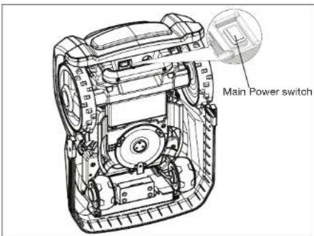
11 Main power switch
12 Control panel
13 Switching power supply x 1
14 Extension cord x 1
15 Fixing peg x 200
16 Measurement ruler (located on box) x 2
17 Boundary wire connector x 3
18 Boundary wire x 1 (160m)
Functional description
This Robotic Mower is an autonomous robot used to cut lawn grass. It will remain within an area designated by a boundary wire, start work following a programmed schedule, and return to its docking station as needed. The three sharp blades ensure clean cuts with minimal damage to the plant, leaving behind tiny snippets as natural fertilizer.
TECHNICAL DATA
| Model | SA900B | |
| Max cutting area 900 m | ^2 | |
| Battery | 862618 / 862622 / 1990608 18650-29ELithium-Ion battery, 28 V/2.9 Ah, 79.8Wh | |
| Switching power supply | FY3201500S1 / FY3201500S2/FY3201500S3Input 100-240V AC, 50/60 Hz Output 32 VDC, 1.5A | |
| Typical mow time on one charge 60 min | ||
| Rated voltage 28 V DC | ||
| Rated power | 50 W | |
| No load cutting speed | 3500 min^-1 | |
| Cutting width 18 cm | ||
| Blade model / part number 846210 | ||
| Cutting height adjustment 5 Settings | ||
| Cutting height, min-max 20 mm-60 mm | ||
| Wireless Frequency Rang/Power | 2.4-2.4835 GHz/<0 dBm | |
| Charging time 60 min | ||
| Degree of protection: | ||
| Robotic Mower IP 24 | ||
| Switching power supply IP 67, PLUG IP 44 | ||
| Robotic Mower weight | 8.5 Kg | |
| Docking station weight 2 Kg | ||
| Frequency Band | 0-148.5 kHz | |
| Magnetic Field Strength 72 dBμA/m | ||
| Gross weight | 16.5 kg | |
| Measured sound power level | ||
| Measured sound pressure L_pp | 53 dB, K=3 dB | |
| Measured power pressure L_ss | 64 dB, K=3 dB | |
* WARNING: For the purposes of recharging the battery, only use the detachable supply unit provided with this appliance.a
SAFETY PRECAUTIONS SAFETY PRECAUT
This section covers the basic safety instructions when working with this machine.
General notes on safety

This machine can cause serious injury if it is not used properly. Please read these operating instructions carefully and familiarise yourself with all the control elements before operating this machine.
Keep these operating instructions in a readily accessible place so that this information is always at your disposal.
Please note that despite all measures to integrate safety measures into the construction, the safety devices and supplemental safety measures, a residual risk remains when using this machine.
Symbols used in the manual

Warning symbols with information on damage and injury prevention.

Warning symbol with information on the danger of electric shock.
Symbols on the machine

Attention!
These instructions must be read.

Danger of injury due to flung-out material! Keep bystanders well away from the machine.
WARNING - Do not ride on the machine. CAUTION - Do not touch rotating blade.
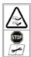
WARNING – Keep your hands and feet away from the rotating blades. Never place your hands or feet close to or under the body when Robotic Mower is in operation.

Return any discarded batteries to your local dealer, collector or recycle point.
It is not permitted to dispose of this product as normal household waste. Please recycle where facilities exist. Check with your local authority or retailer for recycling advice.

Class III equipment2

A product placed on the United Kingdom market meets the UKCA Marking requirements
GBG
SAFETY PRECAUTIONS SAFETY PRECAUT
Warning Symbols on the switching power supply

Warning!

Before use, refer to the corresponding paragraph in the manual.

Double insulation

Pole orientation

Waste electrical products should not be disposed of with household waste. Recycle where facilities exist. Check your local authority or retailer for recycling advice.

CE conformity mark

SMPS (Switch mode power supply unit) incorporating a short-circuit-proof safety isolating switching power supply

SMPS(Switch mode power supply unit)
Ta:45 °C Rated maximum ambient temperature 45 °C

The charger is for indoor use only.

A product placed on the United Kingdom market meets the UKCA Marking requirements
Warning Symbols on the battery pack

Li-lon
Batteries contain Li-lon and should not be disposed with general household waste. Contact your local authority for disposal advice.

Do not throw into water.

Do not throw on to fire.

Do not subject the battery to strong sunlight over long periods and do not leave it in high temperatures.(max.45 °C).

Waste electrical products should not be disposed of with household waste. Recycle where facilities exist. Check your local authority or retailer for recycling advice.
GBG
SAFETY PRECAUTIONS SAFETY PRECAUT
Additional safety instructions for Robotic Mowers
Do not store anything heavy on the top of the Robotic Mower or docking station both during storage or when in use.
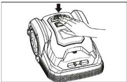
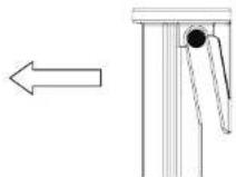
Never use the device if the main power switch (11) is damaged or does not work properly. Never modify the main power switch. Set the main power switch to OFF before storage or when the device is not in use. Use the original packaging when transporting the Robotic Mower, especially for long distances.
If you need to carry the Robotic Mower from or within the working area, first press the STOP button (2) to stop the device.
natural_image
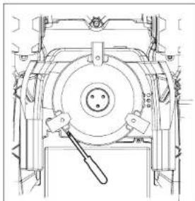
Line drawing of a hand operating a mounted robotic lawn mower (no text or symbols)Secondly, ensure that the main power switch (11) is switched OFF before you lift up the Robotic Mower.
Thirdly, close the top cover, and carry the Robotic Mower using the carry handle (10) at the rear under the mower, keeping the blade disc away from your body as shown.
natural_image
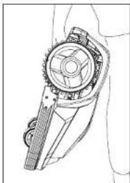
Technical line drawing of a mechanical gear assembly (no text or symbols)Note: The carry handle (10) includes two safety switches. Lifting the device by the carry handle will trigger the switches, deactivating the Robotic Mower.
SAFETY PRECAUTIONS SAFETY PRECAUT
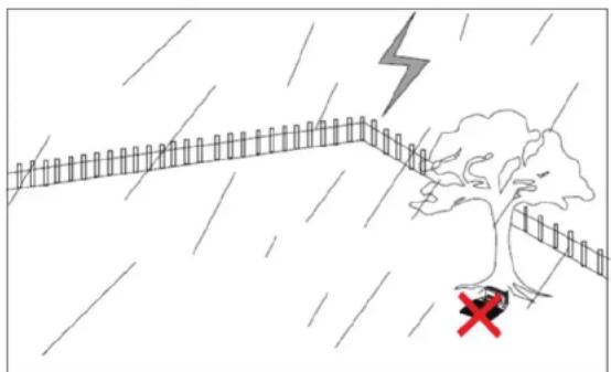
Lightning Protection
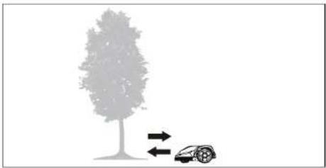
In order to prevent lightning damage to the machine, do not place the docking station under tall trees.
natural_image
Illustration of a tree crossing a wet concrete path with a lightning bolt and red cross symbol (no text or labels)Operating the machine:

WARNING! This machine can cause serious injury. Follow instructions below to reduce risk of accident and injury.
IMPORTANT READ CAREFULLY BEFORE USE KEEP FOR FUTURE REFERENCE
Preparation:
- Read the instructions carefully and make sure you understand them fully. Be familiar with the controls and the proper use of the machine.
- Never allow children, persons with reduced physical, sensory or mental capabilities or lack of experience and knowledge or people unfamiliar with these instructions use the machine.
- Local regulations may restrict the age of the operator. Children should be supervised to ensure that they do not play with the appliance.
- The operator or user is responsible for accidents or hazards occurring to other people or their property.
- Ensure the correct installation of the perimeter boundary system as instructed.
- Periodically inspect the area where the machine is to be used and remove all stones, sticks, wires, and other debris which could cause damage to the machine or be unsafe.
- Periodically inspect to see that the blades, blade bolts and cutter assembly are not worn or damaged. Replace worn or damaged blades and bolts in sets to preserve balance.
- On multi-spindle machines, take care as rotating one blade can cause other blades to rotate.
- Never leave the machine unattended while other people such as children and pets are in the area.
- Never use the machine to level out uneven patches.
- If the blades no longer cut correctly or if the motor is overloaded, check all the parts of your equipment and replace the worn parts. If a more extensive repair is required, contact the customer service centre.
SAFETY PRECAUTIONS SAFETY PRECAUT
Use:
- Never operate the machine with defective guards or without safety devices, for example deflectors and/or grass catchers, in place.
- Do not put hands or feet near or under rotating parts.
- Never pick up or carry the machine while the motor is running.
- Turn OFF / Power OFF the machine
– before clearing any blockages.
– before checking, cleaning or maintaining the machine. - Start the Robotic Mower according to the instructions. When the main power switch (11) is in the ON position, make sure you keep your hands and feet away from the rotating blades.
- Never lift the Robotic Mower or carry it around with the mains switch is in the ON position.
- Do not let people use the mower who do not know how it works or behaves.
- Do not put anything on top of the Robotic Mower or its docking station.
- Do not use the Robotic Mower with defective blade discs, body, defective blades, screws, nuts etc.
- Avoid operating the machine in wet grass. Doing so can cause additional wear and tear, and will increase the amount of cleaning required.
Work interruptions:
- After the machine has been turned off, the cutting cylinder will continue to rotate for a few seconds. Keep hands and feet well away.
- Only remove blockages when the machine is standing completely still.
- Switch off the power when the machine is transported, lifted or tilted.
- Never leave the machine unattended. Children should be supervised to ensure that they do not play with the appliance.

CAUTION!
The following below outlines measures to avoid damage and harm to both the Robotic Mower and the people using it.
Taking care of your machine:
- Switch off the power when the machine is to be carried across uneven surfaces, for example steps.
- Inspect the machine before each use. Never operate the machine if safety devices (e.g. impact protector, parts of the cutting facility or bolts) are missing, worn out or damaged. Check the power cable. To avoid imbalance, all tools and bolts should be changed as complete sets.
SAFETY PRECAUTIONS SAFETY PRECAUT
- Only use spare parts and accessories that have been supplied or recommended by the manufacturer. The use of alien parts results in the immediate loss of all guarantee claims.
- Ensure that all nuts, bolts and screws are firmly tightened and that the machine is in a safe working condition.
- Never try to repair the machine yourself, unless you have been trained accordingly. All work that has not been listed in these instructions must only be carried out by authorised servicing agencies.
- Treat the machine with the greatest care. Always keep the tool clean. Follow the maintenance instructions.
- Never overload the machine. Always work within the specified capacity range. Do not use low-power machines for heavy-duty work. Do not operate the machine for purposes for which it is not intended.
Electrical safety:

CAUTION!
The following states how to avoid accidents and injuries due to electric shock:
- Before each use, carry out a visual inspection of the power and extension cord for any signs of damage or ageing. Damaged mains power cables increase the risk of electric shock.
-
Connect the machine to a power socket with a residual-current circuit breaker that has a rated current of no more than 30 mA.
-
Always keep the extension cable well away from the cutting tools. If the power cable becomes damaged during work, instantly disconnect the power cable from the mains. DO NOT TOUCH THE POWER CABLE BEFORE IT HAS BEEN DISCONNECTED FROM THE MAINS! Risk of electric shock.
- The supply cord cannot be replaced. If the cord is damaged the appliance should be scrapped.
- Keep extension cable away from blades and other moving parts. They may damage the cable and result in contact with live parts.
- Check that the mains voltage is the same as indicated on the rating plate.
Maintenance and storage
- Keep all nuts, bolts and screws tight to be sure the machine is in a safe working condition.
- Replace worn or damaged parts for safety.
- Ensure that only the recommended replacement cutting blades are fitted.
- Ensure that batteries are charged using the charger supplied or recommended by the manufacturer. Incorrect use may result in electric shock, overheating or leakage of corrosive liquid from the battery.
- Servicing of the machine should be carried out according to manufacturer's instructions.
SAFETY PRECAUTIONS SAFETY PRECAUT
- In the event of leakage of electrolyte, flush with water/neutralising agent, seek medical help if it comes into contact with the eyes.
- Store the appliance with battery pack fully charged at room temperature (around 20°C).
- Every deep discharge cycle decreases the capacity of battery pack. To prolong battery life, it is recommended to charge the battery every 6 months over extended periods of time without use.
Transport
The original packaging should be used when transporting the Robotic Mower over long distances.
To safely move from or within the working areas:
- Press the STOP button to stop the mower.
- Move the main switch button to the OFF position if you intended to carry the mower.
- Carry the Robotic Mower using the handle below at the rear. Carry the mower with the blade disc away from the body.
Robotic Mower basic operating principles
- The Robotic Mower chooses its working direction randomly. It will mow your garden completely without leaving behind any uncut part within the area restricted by the chosen boundary.
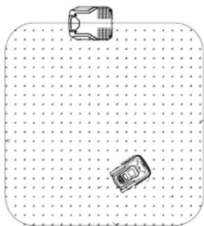
natural_image
Top-down view of a rectangular object with a small circular feature on top, placed on a dotted grid background (no text or symbols)- You define the work area by installing the supplied boundary wire. Once the Robotic Mower detects the boundary wire, it will stop, move backwards and continue mowing in a different direction. It is important to ensure that the boundary is complete. Any objects you wish to protect within the boundary, such as a garden pond, trees, garden furniture or flower beds can also be protected using the boundary wire. The boundary wire must form one complete loop. If the Robotic Mower encounters an obstacle, such as a person, tree, pet or other general garden obstacles, it will stop, move backwards and continue mowing in a different direction.
GBG
SAFETY PRECAUTIONS SAFETY PRECAUT
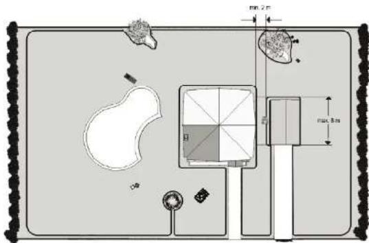
- If you need a narrow corridor to connect two patches of lawn within the boundary, the corridor should be at least 2 metres wide and max. 8 m long.
Note: If the Robotic Mower loses ground contact when hitting an obstacle, the blade disc will stop immediately to avoid any potential damage.
Locating the docking station
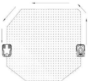
- When the battery is running low, the Robotic Mower will automatically return to the docking station. It will approach the closest boundary wire and follow it anticlockwise (without cutting) back to the docking station. When fully charged, the Robotic Mower will automatically resume the interrupted working cycle. The launch direction from the docking station - clockwise - is hard-wired into the design and is impossible to change.
natural_image
Diagram showing two vehicles moving in a grid-like pattern with directional arrows (no text or symbols)Recognising the boundary wire
- Note that before stopping and changing the direction, the Robotic Mower will overrun the boundary wire by 10 to 20 cm. Please keep this in mind when planning the boundary wire installation.
SAFETY PRECAUTIONS SAFETY PRECAUT
Starting and stopping while mowing
- If you want to stop the Robotic Mower at any time during cutting, press the STOP button (2). Pressing the STOP button will also open the top cover, providing access to the control interface. The Robotic Mower will not start working again until you have closed the top cover.
Robotic Mower mowing limitations
- During first use, the Robotic Mower is set to work 7 days a week. You can adjust the daily working time to match your garden.
- In case a neighbour is using the same Robotic Mower, you will need to keep a distance of 0.5m between you and your neighbour's boundary wires. Otherwise, the two devices might interfere with each-other. Additionally, ensure that your docking station is positioned at least 10m away from your neighbour's boundary wires. Finally, ensure that the adjacent boundary wires are using different signals. Please refer to section "Signal setting" in order to select signal S1 or S2 for your installation.

Below is a table showing the signal distances for each Robotic Mower. Please note your model and use this information as your guide when designing the boundary layout.
| Model Max field Max. distance to wire | ||
| SA900B 900 m | ^2 | 15 m |
SAFETY PRECAUTIONS SAFETY PRECAUT
Robotic Mower cutting information
- The Robotic Mower has a cutting height setting between 20 mm to 60 mm. If the grass height exceeds 60 mm, cut it to 60 mm or below before using the Robotic Mower. Otherwise the load on the unit will be too large and the cutting efficiency will suffer, we recommend using an ordinary lawnmower or trimmer. Once the installation is complete, adjust the cutting height to the desired setting. Always start in a high cutting position and work your way down to the cutting height you want. Before adjusting the cutting height, always press the STOP button (2) to interrupt the cutting. Then turn the large dial to adjust the cutting height.
Note: Only adjust the cutting height while the Robotic Mower is switched off.
natural_image
Technical line drawing of a mechanical device with open lid and internal components (no text or symbols)- Do not use the Robotic Mower during lightning or thunder storms. In case of damage to the electronic circuitry, unplug the docking station and - if possible - disconnect the boundary wire.
The Robotic Mower cutting efficiency relies on sharp blades, so please keep these in good condition.
ASSEMBLY INSTRUCTIONS ASSEMBLY INST
Installation Guide
This chapter explains how to install the Robotic Mower. Please read this completely before you start the installation.
Introduction
We recommend creating a draft of your lawn, including all obstacles and how these should be protected. This makes it easier to find a good position for the docking station and how to correctly place the boundary wire around your garden perimeter protecting bushes, flower beds etc. You will also need some tools, like a hammer and wire cutters, pliers or scissors.
Cutting limitations
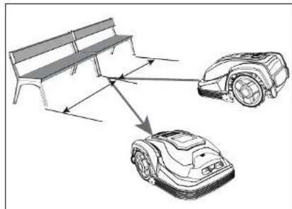
The Robotic Mower is equipped with collision sensors. These will detect any rigid and fixed obstacles higher than 100 mm, such as walls, fences and garden furniture. When triggered, the Robotic Mower will stop, reverse backwards and then continue mowing in a different direction. Still, protecting the obstacles using the boundary wire is the recommended long-term solution.
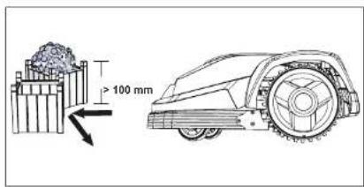
Trees
The Robotic Mower treats trees as common obstacles, but if the roots of the tree are exposed and lower than 100mm, this area should be excluded using boundary wire in order to protect the tree root, cutting blades or rear wheels from damage.
natural_image
Silhouette of a tree with directional arrows indicating movement or motion (no text or symbols)Stones
We recommend clearing the lawn of small (less than 100 mm high) rocks and stones and any stones with a round or sloped edge. The Robotic Mower might try and climb such rocks instead of recognising them as a barrier.
A Robotic Mower getting stuck on such a stone requires user intervention to restart mowing. Contact with stones can result in damage to the blades.
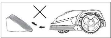
natural_image
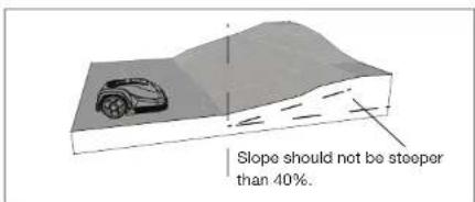
Diagram showing a robotic arm with a cross symbol and an arrow pointing to it, next to a separate irregular object (no text or labels present)Slopes
The Robotic Mower can navigate slopes up to a maximum of 40% incline or decline.
GBG
ASSEMBLY INSTRUCTIONS ASSEMBLY INST
The boundary wire should never run perpendicular to a gradient of more than 10^ . Likewise, please allow a corridor of at least 2m between a 10^ or steeper slope and the boundary wire. Otherwise, the faster downhill speed may cause the Robotic Mower to overshoot the boundary wire, especially on wet and slippery ground.

Paths, Driveways and Roads
If an elevated driveway crosses your lawn, it is advised to keep it outside of the boundary wire.
Please allow a safety distance of 40 cm between driveway and boundary wire.
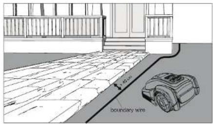
If the driveway and lawn are at the same level, feel free to use the boundary wire to create a corridor. This allows your Robotic Mower to cross the driveway and reach the opposite lawn.

Uneven lawn surfaces
Uneven lawn areas or may cause the blades to touch the ground. We recommend leveling the lawn before using your Robotic Mower or excluding uneven areas using the boundary wire.
natural_image
Line drawing of a robotic lawn mower with motion lines indicating speed (no text or symbols)ASSEMBLY INSTRUCTIONS ASSEMBLY INST
Flowerbeds
Use the boundary wire to exclude any flowerbeds from the cutting area. There are two options for the two lengths of boundary wire running between the flowerbed and the outer boundary:
1) Keep the distance between the parallel wires above 10 cm. This way, the Robotic Mower will recognise the boundary wire as an ordinary obstacle. When cutting, it will "bounce" off it as usual. When following the boundary wire back to the docking station, it will take the detour around the flower bed.
2) Alternatively, keep the distance between the two parallel wires below 5 mm. Do not cross the wires - see below. This way, the Robotic Mower will not recognise the wires and travel across them unhindered. This option requires placing an obstacle on the boundary wire around the flowerbed. Place the obstacle, for example a large rock or pole, near position A indicated on the below illustration. The obstacle must be surrounded by a flat area of about 1 m x 1 m, without any slopes. This obstacle will allow the machine to exit the circle.
Ponds and Pools
While the Robotic Mower is protected against rain and spray water, being submerged is likely to cause severe damage to the electronic parts.
Therefore, it is imperative to exclude any pools from the cutting area. For added safety, we recommend placing a fence around the pool.
General Dos and Don'ts
Do not run the boundary wire directly above an ordinary power cable. The power cable's electric field may distort the boundary signal.
Never cross two boundary wires! This will distort the radio signal and cause erratic behavior of the Robotic Mower.
If you have created a boundary corridor inside your working area, the corridor should be at least 2 m wide and a max length of 8 m.
If a corridor is too narrow or too long, the Robotic Mower might not be able to navigate it from one end to the other.
ASSEMBLY INSTRUCTIONS ASSEMBLY INST
Keep in mind that flowers, bushes and surrounding shrubbery will change in size over a season. Please allow sufficient space between boundary wire and other plants to avoid interference year-around.
natural_image
Diagram of a circular structure with radial arrows indicating flow or movement, surrounded by star-like patterns and directional arrows (no text or symbols)Marking out the Robotic Mower's working area
Now that you understand the basic principals of how the Robotic Mower works, the next step is to mark out the working area with boundary wire by referring to your garden plan. This is a very important part of the installation, so please take care.
Starting from the docking station, the boundary wire must be set in one continuous loop without any breaks or crossings. Connecting the end to the docking stations second connector will complete the circuit.
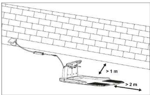
Where appropriate, use the included ruler to check the 40 cm required distance. First, locate the best position for your docking station. Be aware that it needs a permanent connection to the mains, so take into account the location of the nearest power outlet. The included supply cord has a length of 9 m.
The docking station (5) must be placed on a flat surface, at ground level.
natural_image
Technical line drawings of four electronic components: a cylindrical sensor, coiled cable, a rectangular device with grid pattern, and a separate outline (no text or symbols)To ensure the Robotic Mower can return to the docking station smoothly, leave 2m of straight wire to the front of the docking station and 1m to the side facing the cutting area. Use a shaded location for the docking station, as a lower temperature while charging is beneficial to the battery.
Important: Place the docking station on an even, flat surface away from ponds, pools or stairs.
We recommend suitable protection from the elements, for example a robot port or garage.

Pay attention to protect cable!
ASSEMBLY INSTRUCTIONS ASSEMBLY INST
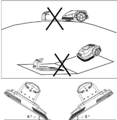
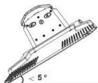
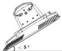
Do not place the docking station too close to a slope, such as at the top of a hill or the bottom of a furrow. Avoid left and right inclination in excess of 5 degrees.
If your lawn has a soft or uneven surface, we recommend fortifying the area around the docking station with a grass protection mesh. Otherwise, the repeated stress of the rear wheels can damage the turf.
Once the position of the docking station is confirmed and mains electrical connection is laid out, do not connect to to the mains power, finish all boundary layout work before connecting the docking station to the power supply.
Pegging out the boundary wire
We strongly recommend mowing the lawn to 60 mm or less before laying out the boundary wire. Burying the boundary wire is entirely optional. Still, the closer to the ground you lay out the boundary wire, the lower the chance of tripping over it or damaging it when mowing the lawn.
In a very short time, the wire will be covered by grass. As the voltage is only 32 V, there is no risk of electric shock.
Unpack the boundary wire (18) and locate the free end. Mark the desired path of the boundary wire with the fixing pegs (15).
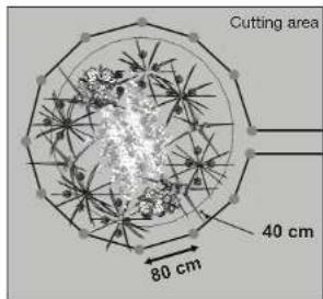
Use the included ruler (16) to ensure the required 40 cm distance between wire and obstacles.
The recommended distance between two pegs is about 80 cm in straight lines, and less in tight curves. Note that the pegs hook and wire silt always faces the outside of the boundary. When first planting the pegs, do not drive them fully into the ground. Use a light hammer to drive them in a little bit. Also locate the fixing pegs and lay each one on the lawn at approximately the correct distance from lawn edges (40cm) and obstacles.
There is a gauge supplied for this.
The pegs should be knocked into lawn with wire location to boundary outside like shown.
Once all pegs are in position, lay out the boundary wire. Start from the docking station. Run the wire through the peg's hook and wire slit one-by-one. Do not tighten the boundary wire too much to prevent wire damage. Carefully prevent any kinks, knots, etc. When cutting the wire, we recommend leaving at least 1 m spare wire to allow for adjustments.

Note: The pegs are not suitable for fixing the boundary wire on hard surfaces, e.g. when running the boundary wire across a driveway. Instead, use appropriate screws and plugs. Be sure to use insulation washers to protect the wire insulation.
GBG
ASSEMBLY INSTRUCTIONS ASSEMBLY INST
Only use the included waterproof boundary wire connectors (17) to join together two pieces of boundary wire.
See below for some further sketches giving more distance guidelines.
Avoid right angles when running the boundary wire around a corner. Instead, separate into two 45° angles.
In case the included boundary wire is too short for your garden, more is available from our service team.
The wire's total length must not exceed 300 m.
Prepare the boundary wire for the docking station
Use a wire stripper to remove 10-15 mm insulation from each end. Twist the threads tight.
natural_image
Technical line drawing of a mechanical component with a tool inserted (no text or symbols)
natural_image
Illustration of two hands tying a string with a ruler above (no text or symbols)Connect the docking station to the boundary wire
Place the docking station on the end of the boundary wire so that the wire runs lengthwise below the middle of the docking station. Connect that end to the left (black) connector marked "F" (front). Connect the other end to the right (red) connector marked "B" (back).
IMPORTANT INFORMATION
Double check that the charger connections are as shown below. Even if there is a blue light, if the connectors are wrongly connected the machine will not work.
ASSEMBLY INSTRUCTIONS ASSEMBLY INST
After connecting the "F" and 'B' connectors to the docking station, the docking station can be fixed down with the boundary pegs.
Before fixing the docking station, please check again that the above mentioned conditions are met:
- Even surface within range of power supply
- 2 m straight boundary in front,
- Inclination less than 5 %
- Surplus boundary wire tucked under the docking station for protection, outside the boundary.
Once the docking station is fixed, connect the charger extension cable (14) to charging base. Now, connect the power supply to the mains outlet. After a brief self-test, one blue LED on the docking station should light up. If all LEDs stay dark, double-check the mains outlet and the power supply. If anything other than a single blue LED lights up, please refer to the chapter on trouble-shooting.
Turn on and test the installation
Once the blue LED confirms all is OK, test the Robotic Mower's function. Check the LED regularly to ensure fixing the boundary wire has not affected the connection. Then place the Robotic Mower in the working area, a few metres beside the docking station. Set the main power switch (11) to "ON". The Robotic Mower will power-up and start a self-test, but will not start working at this time.
natural_image
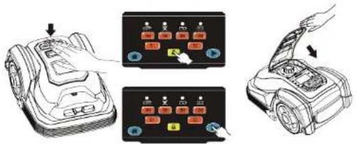
Simple line drawing of two car bodies, one above and one below, with no text or symbols.Press down on the large STOP button (2) to open the top cover and access the controls. Activate the button marked " [ ]" (situated on the left part of the display) and press down the top cover to close it.
Once closed, the Robotic Mower will automatically return to the docking station by locating and following the boundary wire in anti-clockwise direction. If the Robotic Mower fails to dock correctly, move the docking station to a more suitable position.
Once the device has docked, the symbol will start flashing. This indicates that the battery is charging correctly.
After initial installation, the Robotic Mower will remain in the docking station until the battery is fully charged.
Successful docking and charging indicates that you have found a suitable position for the docking station. It is now time to fix it in position by fully driving the pegs into the ground. Take care not to damage or kink the surplus wire stored under the docking station.
GBG
OPERATION
Control Panel
Once the Robotic Mower is fully charged, it is ready for programming.
While the default factory settings will suit the majority of users, it is worth familiarising yourself with the options available.
To start programming, press down on the large STOP button (2) to open the top cover and access the controls.
The control panel has five functional areas.
Zone 1: Status indicator LEDs
Zone 2: Working time setting
Zone 3: Signal setting
Zone 4: Locking button
Zone 5: Home & start button
Lock and Unlock
Unlock
A blinking LED above the lock button [icon] indicates that the control panel is locked. To unlock the control panel, enter the PIN code.
There is no factory-default PIN. Instead, press the lock button [Hour times.
If the LED goes out, the PIN entry was successful and the control panel was unlocked.
OPERATION
Lock
Control panel will be locked when the Robotic Mower is restarted using the mains power switch.
Also, you can simply press the lock button [🔒] to manually lock the control panel.
Change PIN code
The analog keyboard
The panel is equipped with a 5 key numerical keyboard.
Use '4H' for 0, "6H" for 1, "8H" for 2, "10H" for 3, "S1" for 4, and "S2" for 5.
Changing the PIN Code
1) Switch OFF the mains power switch (11)
2) Press and hold the lock button
3) Hold down the lock button [While switching ON the main power switch (11). After about 6 seconds, all LEDs on the control panel will start flashing fast.
4) Release the lock button [🔒].
5) Within 6 seconds, enter your new PIN-Code.
The Robotic Mower will confirm the changed PIN with a single beep.
6) All LEDs will go out and the Robotic Mower will reboot. Once the LED of the lock button [icon] flashes, the reboot is complete. You can now unlock your Robotic Mower with your new PIN.
Note: If you do not remember your PIN code, please set a new PIN as described above.
It is not possible to reset the device to the default PIN code of "4x [

GBG
OPERATION
Status indicator LEDs
Lift signal

A red LED above this symbol shows that the lift sensor has triggered.
Note: Vibrations or collisions can also trigger the lift sensor.
If this sensor is triggered for less than one second, the Robotic Mower will resume its work schedule immediately.
If the lift sensor is triggered for more than 1 second but less than 8 seconds, the Robotic Mower will stop operating for a short amount of time, then restart. If the Robotic Mower's lift signal is triggered for more than 8 seconds, this will trigger the anti-theft system. The device will lock itself and an alarm will sound.
Boundary wire signal
The boundary wire emits an electromagnetic signal. The Robotic Mower uses this signal to determine if it is within the cutting area.

The red LED above this symbol flashes when the device does not receive the "within dary" signal. In this case, the Robotic Mower will stop mowing immediately.
Low battery symbol
This LED will turn on when the battery charge is low. In this case, the Robotic Mower will immediately return to the docking station.
Charging
This LED will flash while the battery is charging. A continuous LED indicates a fully charged battery.
While charging, the boundary signal receiver is powered off to save energy. This can cause the "boundary wire signal" LED to turn on.
OPERATION
Working time setting

The above buttons let you choose the mower's daily working hours.
Please refer to the below table for the recommended working time per day, depending on the working area.
The current working time is indicated by the illuminated button.
A flashing button means that the device has already worked the respective hours that day.
Note: The average working time with a fully loaded battery is less than the minimal working time setting of 4 h. When the Robotic Mower returns to the docking station, the clock does not stop. The charging time counts as working time.
| Recommended time per day(hour) | |
| 300m^2 | 3 hours |
| 900m^2 | 9 hours |
After the working time is selected, the corresponding LED will be lit up LED flash means out of working time.
Signal setting

To avoid interference with a second Robotic Mower, there are two different boundary signals available.
Be sure to choose the same signal (S1 or S2) for the docking station and the Robotic Mower.
Use the control at the back of the docking station to switch between signal S1 and S2.
OPERATION
Press S1 or S2 on the control panel to match the Robotic Mower's signal to the docking station's. The button of the currently active signal is illuminated.

Home & start button
Press the START button and close the top cover and the Robotic Mower will begin cutting. When the programmed work time is passed, the device will return to the docking station.
Important note:
The Robotic Mower will start working again the following day at the same time as when the start button was pressed initially. Example: You start the Robotic Mower on Monday at 15:30 with a working time of 4 h. The device will work on Monday until 19:30 and then return to base. On Tuesday 15:30, the Robotic Mower will automatically start again working for the same 4 h. This will continue every day until interrupted by the user.
HOME
Pressing the HOME button and closing the lid will send the Robotic Mower back to the docking station for a complete recharge. Note this will not stop the current programming. If the working time has not run out when charging is complete, the device will start cutting again. It will also start working again on the following day.
STOP
To interrupt the automatic working schedule, press the STOP button to open the top cover, and close it again without pressing any control button. The Robotic Mower will beep five times to confirm the interruption. It will not resume working without further user commands.
OPERATION
Edge cutting
As the first cutting action of each day, the Robotic Mower will trim the lawn edge. Therefore, while cutting, it follows the boundary wire in clockwise direction.
This function only engages when the Robotic Mower launches from the charging station.
Charging Information
The Robotic Mower will go back to docking station by itself in the following situations:
-
When you press the button and close the keypad top cover.
-
When out of working time set.
-
When less than 30 % battery charge is remaining.
Note: If the Robotic Mower fails to dock to the docking station, it will return to the cutting area and try again.
Note: If the ambient temperature around docking station is higher than 40 °C , the device will stop charging to protect the battery. Once the temperature drops sufficiently, charging will resume automatically.
Rain Sensor
natural_image
Diagram showing a lawn mower with rain cloud and gear, next to a treadmill (no text or symbols)CLEANING/MAINTENANCE

Work that has not been described in these instructions must be carried out by a servicing agency authorised by the manufacturer. Only use original parts.
Maintenance
Check and clean your Robotic Mower regularly and replace worn parts if necessary.
Preferably use a dry brush, a damp cloth or a sharpened wooden piece.
Never use flushing water.
Following these maintenance instructions can extend your Robotic Mower's service life.
Battery Life
The Robotic Mower has a maintenance free Li-ion battery, with an estimated life of more than 2 years (depending on treatment and usage).
Winter Storage
During winter, keep your mower, docking station and power supply in a dry place.
We recommend a shed, garage or preferably store it indoors.
Prepare your device for winter storage as follows:
- Fully recharge the battery.
- Set the main power switch to "OFF"
- Thoroughly clean your Robotic Mower.
- Unplug the power supply from the mains outlet.
- Disconnect the power supply from the docking station.
- Disconnect the boundary wire from the docking station. Lift up the docking station, and clean it. The boundary wire can remain outside. However, it is imperative to protect the wire against corrosion. We recommend a water-free grease or suitable sealing tape. If available, repack the product in the original packaging.
Alternatively, our service centre offers a winter service for your device. This will include a check-up of all parts and - if available - a software upgrade.
natural_image
3D technical illustration of a car inside a box (no text or symbols)CLEANING/MAINTENANCE
Preparing for spring
After winter storage, please clean the charging contacts on both the Robotic Mower and the docking station.
Use a fine abrasion paper or a brass brush; this will help to achieve the best charging efficiency and avoid any charging interference.
Cleaning and Maintenance
It's important to keep your Robotic Mower clean.
The mower will deal with slopes easier when the wheels are clean. Sharp cutting blades need less power and will result in cleaner cuts.
Remember to turn off the main power switch (11) before starting any maintenance. Use protective gloves when handling the blades! Never use a high pressure washer, garden hose or running water when cleaning the device.
Cleaning the mower body
As your Robotic Mower is battery powered you need take care when cleaning. Remove rough dirt with a soft brush. Use a manual water spray with mild household detergent for intensive cleaning. Wipe off any residue after cleaning with a moist rag.
natural_image
Line drawing of a robotic vacuum cleaner with spray bottle and fan (no text or symbols)GBG
CLEANING/MAINTENANCE CLEANING/MAIN
Cleaning the underside
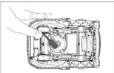
Ensure the main power switch (11) is in OFF position. Wear protective gloves. Turn the Robotic Mower onto its side to expose its underside. Clean the blade disc and frame using a soft brush or damp cloth. Rotate the blade disc to make sure that it moves freely, and check that the blades can turn on their pivots and no grass is obstructing them.
natural_image
Technical line drawing of a mechanical assembly with hand operating a tool (no text or symbols)Clean the contact pins and the charging strips
Using wire wool, metal cleaner or very fine grade emery paper, clean the contact pins and the charging strips on your mower and docking station. Remove any debris, leaves, or grass clippings around the contact pins and charging strips to ensure efficient charging.
Reversing or replacing the blades

WARNING!
Ensure the Robotic Mower is completely shut off before cleaning, adjusting or replacing the blades. Always wear protective gloves.

WARNING!
To ensure maximum cutting efficiency and safety, always use recommended replacement blades and blade mounting parts when replacing.
natural_image
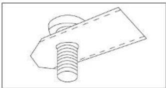
Technical line drawing of a bolt and plate assembly (no text or symbols)Your Robotic Mower has three blades, fixed to the blades disk.
Unless damaged by hard obstacles, these blades can last for up to five months of everyday use.
Weekly inspection of the blades and the fixing screws is required. Note that the blades are double-edged. Once the first side is blunt, loosen the fixing screw. Turn the blade upside-down and fix it again with the fixing screw. After tightening the fixing screw, verify that the blade can rotate freely around the screw.
A set of spare blades is included with the Robotic Mower. More are available from customer support. The blade's spare part number is 846210.
Only use original spare parts. For best performance and avoiding imbalance, always turn or replace all three blades at the same time.
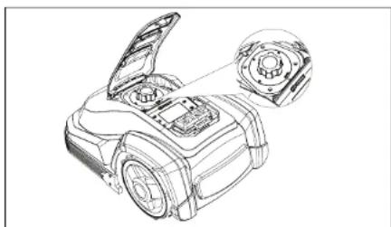
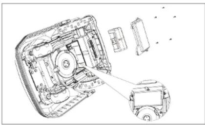
Replacing the battery
natural_image
Technical line drawing of a mechanical component with a central circular housing and a handle (no text or symbols)While the actual battery life will depend on usage and environmental factors, the typical service life is several years. Spare batteries are available from customer support. To replace the battery, please follow the instructions below.
1) Ensure the main power switch (11) is turned OFF. Clean the underside as instructed.
2) Set the Robotic Mower to the lowest cutting height.
3) Turn the mower upside-down. Remove the 5 screws fixing the battery compartment's lid. Note one screw is partially covered by the blade protector and is only accessible through a service hole.
4) Pull out the battery and disconnect it from the Robotic Mower.
5) Carefully clean the lid and the edge of the battery compartment. Debris may allow excessive water to enter the battery compartment, causing major damage to the device.
6) Connect and insert the replacement battery, close the compartment and fix the lid with 5 screws. Do not turn on the Robotic Mower before placing it back on its wheels - beware of sharp blades!
CLEANING/MAINTENANCE
natural_image
Technical line drawing of a mechanical assembly with exploded view and close-up detail (no text or symbols)Short-time storage
- Store the machine in a dry place well out of reach of children.
- Do not wrap nylon sacks around the machine, as this could result in the formation of moisture.
TROUBLESHOOTING
Troubleshooting for the docking station
| LED Description | ||
| 1 | Blue light on Normal | |
| 2 | Blue flash, Red off Docking station internal error, boundary wire OK | |
| 3 | Red flash, Blue off | Docking station OK; boundary wire connection is poor or the Robotic Mower is charging. |
| 4 | Red and Blue flash | Docking station internal error; boundary wire connection is poor or broken |
Troubleshooting for the Robotic Mower
| Nr. | Message Symptom Action | ||
| 1 | NONE | Robotic Mower cannot dock with docking station | 1. Check if boundary wire under and in front of the charger is in a straight line.2. Check that the docking station's position is suitable as explained in this manual. |
| 2 | NONE | Robotic Mower runs in circles while mowing or while following boundary wire back to docking station. | 1. Verify that no power cable runs parallel and in close proximity the boundary wire. If necessary, reposition the boundary wire.2. Check if a front wheel is stuck.3. If a neighbor has a similar Robotic Mower, the signals may interfere. Try setting your docking station and Robotic Mower to the alternative boundary signal.4. Driving motor may be damaged, please contact customer support |
| 3 | NONE | The Robotic Mower is very noisy. | 1. Inspect the blade fixing screws; tighten if necessary.2. Inspect the blades for damage; replace if necessary.3. Grass too high. Increase cutting height. Alternatively, mow the lawn with an ordinary lawnmower firstly, choosing a cutting height just above the desired cutting height.4. Cutting motor failure, please call after sales service |
| 4 | NONE | Mower remains at or returns to docking station when pressing START and closing the lid. | 1. Check if the mower already completed the programmed working time for that day.2. Check if the battery is very low |
| 5 |  | Lift-sensor triggered | 1. Too-high and dense grass (taller than 60 mm) may cause the Robotic Mower to lift. Mow the lawn with an ordinary lawnmower.2. Check the mower is free from obstructions. |
TROUBLESHOOTING
| Nr. | Message Symptom Action | ||
| 6 | LED flash | The Robotic Mower does not receive the boundary wire signal.(Robotic Mower placed inside boundary area.) | 1. Verify that the docking station indicator light is blue. If not, refer to installation instructions and docking station troubleshooting.2. Verify that both docking station and Robotic Mower are set to the same signal, S1 or S2.3. Check if the boundary wire is connected in the correct direction.4. Disconnect the boundary wire from the docking station, and reconnect it the opposite way. |
| 7 | LED flash | Battery voltage is too low to perform normal mowing. | 1. Normally if voltage is low, the mower should automatically return to the docking station.2. If not, please carry your mower manually to docking station when it has stopped on the lawn. |
| 8 | LED flash | Charging Wait for battery | to recharge. |
| 9 | Reset factory defaults | 1. Switch OFF the device.2. Place Robotic Mower on flat, even surface.3. While pressing and holding the START button, switch ON the device.4. The Robotic Mower will boot up. All LEDs flash.5. Release START button. Factory reset is complete.Note: The Robotic Mower must stand on a flat surface, because the inclination sensors are also zeroed. | |
DECLARATION OF CONFORMITY
Declaration of Conformity We
MEROTEC GmbH
Otto-Brenner-Str. 8
47877 Willich, Germany
Declare that the product:
Description: 28V Robotic Mower
Model No. SA900B
Function: Cutting grass
Conforms to the following directives and standards
Machinery Directive 2006/42/EC
EN 60335-1:2012+A11+A13+A1+A14+A2, EN 50636-2-107:2015+A1
+A2. EN 62233:2008
Radio Equipment Directive 2014/53/EU
NB0123. TÜV SUD Product Service GmbH Ridlerstraße 65.80339
Munich.Germany Certificate No:TPS-RED001232 i04
EN 55014-1:2017:
EN 55014-2:2015:
EN 301 489-1 V2.2.3:
EN 301 489-3 V2 1 1
EN 300 328 V2.2.2
EN 301 489-17 V3.2.4
Draft EN 303 447 V1.2.0
EN 62311:2008;
RoHS Directive 2011/65/EU
WEEE Directive (2012/19/EU)
Authorized Signatory
Poland Hou Lien
Signature:
Place: Willich
Name: Roland Menken
General Manager
Date: 2021-05-18
MEROTEC GmbH
Otto-Brenner-Str. 8
47877 Willich, Germany
CE
DECLARATION OF CONFORMITY
To the provisions of Council Directives
We
SUMEC UK Co., Ltd.
Unit A&B, Escrick Business Park
Escrick, York YO 19 6FD
Declare that the product:
Description: 28V Robotic Mower
Model No. SA900B
Function: Cutting grass
Conforms to the following directives and standards
Supply of Machinery (Safety) Regulations 2008
EN 60335-1:2012+A11+A13+A1+A14+A2, EN 50636-2-107:2015+A1
+A2, EN 62233:2008
Radio Equipment Regulations 2017
NB0123, TUV SUD Product Service GmbH Ridlerstraße 65.80339
Munich.Germany Certificate No:TPS-RED001232 i04
EN 55014-1:2017:
FN 55014-2:2015:
EN 301 489-1 V2.2.3:
EN 301 489-3 V2.1.1:
EN 300 328 V2.2.2
EN 301 489-17 V3.2.4
Draft EN 303 447 V1.2.0
EN 62311:2008;
The Restriction of the Use of Certain Hazardous Substances in
Electrical and Electronic Equipment Regulations 2012
Authorized Signatory
Date: 2021-05-18

Signature:_
Place: York
Name: Mariana Hall
General Manager

SUMEC UK
Unit A&B Escrick Business Park
Escrick, York
YO19 6FD
natural_image
Line drawing of a hand pressing down on a small robotic vacuum cleaner's side panel (no text or symbols)natural_image
Technical line drawing of a mechanical device with gears and shaft (no text or symbols)natural_image
Illustration of a tree crossing a wetland barrier with a lightning bolt and red cross symbol (no text or labels)natural_image
Top-down view of a rectangular object with two small protrusions on a dotted grid background (no text or symbols)natural_image
Diagram showing two vehicles on a grid-patterned rectangular area with directional arrows (no text or symbols)natural_image
Technical line drawing of a mechanical device with open lid and internal components (no text or symbols)
MONTAGEANLEITUNG
Bäume
natural_image
Simple illustration of a tree with directional arrows indicating movement or motion (no text or symbols)Steine
natural_image
Diagram showing a robotic arm with a cross symbol indicating collision or failure, next to a gray gear-like object (no text or labels present)natural_image
Line drawing of a robotic lawn mower on a curved surface (no text or symbols)natural_image
Diagram of a medical or laboratory setup with an apple-shaped object, a monitor, and directional arrows (no text or symbols)natural_image
Technical line drawings of four electronic components: a cylindrical sensor, coiled cable, a rectangular device with grid pattern, and a connector (no text or symbols)
natural_image
Diagram showing three vehicles with cross symbols indicating no intersection or violation, no text or labels present
natural_image
Technical line drawing of a mechanical component with a tool inserted (no text or symbols)
natural_image
Illustration of two hands holding a thin wire with a scale bar (no text or symbols)natural_image
Top-down view of two car models (no text or symbols visible)natural_image
Diagram showing a lawn mower, rain cloud, and treadmill with an arrow indicating motion (no text or symbols)REINIGUNG/WARTUNG

natural_image
3D diagram of a car inside a box, showing internal components (no text or symbols)REINIGUNG/WARTUNG
natural_image
Line drawing of a robotic vacuum cleaner with spray bottle and fan (no text or symbols)natural_image
Technical line drawing of a mechanical assembly with a hand holding a tool (no text or symbols visible)natural_image
Technical line drawing of a bolt and nut assembly (no text or symbols)natural_image
Technical line drawing of a mechanical component with no visible text or symbolsnatural_image
Technical line drawing of a mechanical device showing internal components and assembly (no text or symbols)natural_image
Line drawing of a hand operating a mounted robotic device with a control panel (no text or symbols)natural_image
Technical line drawing of a mechanical device with gears and shaft (no text or symbols)natural_image
Illustration of a tree crossing a rain barrier with a lightning bolt, no text or symbols presentnatural_image
Two small electronic components on a dotted grid background, no text or symbols visiblenatural_image
Top-down diagram of a vehicle on a dotted grid surface with two cars, no text or symbols presentCONSIGNES DE SÉCURITÉ CONSIGNES DE
natural_image
Technical line drawing of a mechanical device with open lid and internal components (no text or symbols)
CONSIGNES D'ASSEMBLAGE
Arbres
natural_image
Silhouette of a tree with two arrows pointing to a small car (no text or symbols)Pierres
natural_image
Diagram showing a robotic car with a cross symbol indicating collision or failure, alongside a separate 3D object (no text or labels present)Pentes
natural_image
Line drawing of a robotic lawn mower with motion lines (no text or symbols)CONSIGNES D'ASSEMBLAGE
Plates-bandes
natural_image
Diagram of a circular structure with radial arrows indicating flow or movement, surrounded by a textured surface (no text or symbols)CONSIGNES D'ASSEMBLAGE
natural_image
Technical line drawings of four electronic components: a coiled cable, coiled wire, a perforated housing, and a mechanical component (no text or symbols)
natural_image
Diagram showing three car-related symbols: a robotic arm, a robotic vehicle, and a robotic device on a flat surface (no text or labels)
natural_image
Technical line drawing of a mechanical component with two views showing angular measurements (5° and <5°), no text or symbols present.natural_image
Technical line drawing of a mechanical component with no visible text or symbols
natural_image
Illustration of two hands holding a tool, with a small inset showing a wire or cable (no text or symbols)natural_image
Simple line drawing of two vehicles on a horizontal surface (no text or symbols)CONSIGNES D'ASSEMBLAGE
natural_image
Diagram showing a rain-dry robot with cloud and snow, moving toward a treadmill (no text or symbols)
natural_image
3D diagram of a car inside a box, showing internal components (no text or symbols)NETTOYAGE/ENTRETIEN
natural_image
Line drawing of a robotic vacuum cleaner with spray bottle and fan (no text or symbols)NETTOYAGE/ENTRETIEN
natural_image
Technical line drawing of a mechanical assembly with a hand operating a tool (no text or symbols visible)natural_image
Technical line drawing of a bolt and nut assembly (no text or symbols)NETTOYAGE/ENTRETIEN
natural_image
Technical line drawing of a mechanical component with no visible text or symbolsnatural_image
Technical line drawing of a mechanical device showing internal components and a close-up view of a small vehicle (no text or symbols present)RoHS Directive 2011/65/EU
WEEE Directive (2012/19/EU)
Poland Muslin
Signature:
Lieu: Willich
Nom: Roland Menken
Directrice générale
Date: 2021-05-18
MEROTEC GmbH
DÉCLARATION DE CONFORMITÉ
Nous
SUMEC France
TRANS Directive 2011/09/LO WEEE Directive (2018/10/F)

Signature:
Lieu: Saint Cyr Sur Loire
Nom: Rodolphe Dubois
Directrice générale
Date: 2021-05-18
SUMEC France
Warning Symbols on the charger

Waarschuwing!
NLNL

natural_image
Line drawing of a hand operating a mounted robotic lawn mower (no text or symbols)natural_image
Technical line drawing of a mechanical device with gears and shaft (no text or symbols)natural_image
Illustration of a tree crossing a wetland path with a lightning bolt and red cross symbol (no text or labels)De machine bedienen:

natural_image
Top-down view of a grid-patterned surface with two small icons (no text or symbols)VEILIGHEIDSMAATREGELEN VEILIGHEIDSMA
natural_image
Top-down diagram of a vehicle on a grid-patterned rectangular area with directional arrows (no text or symbols)natural_image
Technical line drawing of a mechanical device with open lid and internal components (no text or symbols)
Bomen
natural_image
Silhouette of a tree with directional arrows indicating movement or motion (no text or symbols)Stenen
Hellingen
natural_image
Line drawing of a robotic lawn mower with motion lines (no text or symbols)MONTAGE-INSTRUCTIES MONTAGE-INSTR
Bloemenperken
De meegeleverde stroomkabel is 9 m lang.
natural_image
Technical line drawings of four electronic components: a cylindrical sensor, coiled cable, a rectangular device with grid pattern, and a connector (no text or symbols)
Bescherm tevens de kabel!
MONTAGE-INSTRUCTIES MONTAGE-INSTR
natural_image
Diagram showing three vehicles on a flat surface with no visible text or symbols
The pegs should be knocked into lawn with wire location to boundary outside like shown.
natural_image
Technical line drawing of a mechanical component with a tool inserted (no text or symbols)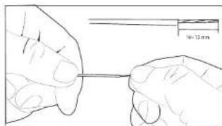
natural_image
Illustration of two hands holding a thin wire with a 10.15mm scale bar (no text or symbols on the diagram itself)natural_image
Simple line drawing of two vehicles, one with a small car and the other with a front-mounted device (no text or symbols)Zone 1: Statusindicator LED's
REINIGING EN ONDERHOUD

natural_image
3D diagram of a car inside a rectangular housing (no text or symbols)REINIGING EN ONDERHOUD
natural_image
Line drawing of a robotic vacuum cleaner with spray bottle and fan (no text or symbols)REINIGING EN ONDERHOUD REINIGING EN O
natural_image
Technical line drawing of a mechanical assembly with hands operating a tool (no text or symbols visible)Reinig de contactpennen en de laadstroken
natural_image
Technical line drawing of a bolt and plate assembly (no text or symbols)natural_image
Technical line drawing of a mechanical component with no visible text or symbolsnatural_image
Technical line drawing of a mechanical assembly with exploded view and close-up detail (no text or symbols)Kortstondige opslag
RoHS Directive 2011/65/EU
WEEE Directive (2012/19/EU)

Handtekening
Plaats: Willich
Naam: Roland Menken
Algemeen directeur
Datum: 2021-05-18
MEROTEC GmbH
RoHS Directive 2011/65/EU
WEEE Directive (2012/19/EU)

Handtekening:
Symbols on the machine

Upozornění!
natural_image
Line drawing of a robotic vacuum cleaner with a hand adjusting the component (no text or symbols)natural_image
Technical line drawing of a mechanical device with gears and shaft (no text or symbols)natural_image
Illustration of a tree crossing a rain barrier with a lightning bolt and a red cross symbol (no text or labels)Ovládání stroje:

natural_image
Top-down view of a rectangular object with two small circular features on a dotted grid background (no text or symbols)natural_image
Top-down schematic of a hexagonal grid pattern with directional arrows indicating flow or movement (no text or symbols)natural_image
Technical line drawing of a mechanical device with open lid and internal components (no text or symbols)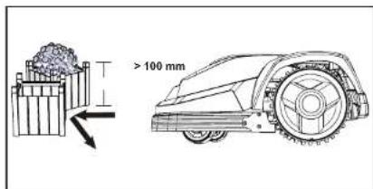
Stromy
natural_image
Silhouette of a tree with directional arrows indicating movement or motion (no text or symbols)Kameny
natural_image
Diagram showing a robotic arm with a cross symbol indicating collision or failure, next to a gray gear-like object (no text or labels present)Svahy
natural_image
Line drawing of a robotic lawn mower with motion lines (no text or symbols)MONTÁŽNÍ NÁVOD MONTÁŽNÍ NÁVOD
Květinové záhony
natural_image
Diagram of a circular biological or mechanical structure with internal components and directional arrows, no visible text or symbols.natural_image
Technical line drawings of three electronic components: a coiled cable, a coiled wire, and a rectangular device with internal structure (no text or symbols)natural_image
Diagram showing two robotic vehicles with cross marks on a flat surface, no text or symbols present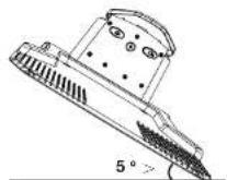
natural_image
Technical line drawing of a mechanical component with a tool inserted (no text or symbols)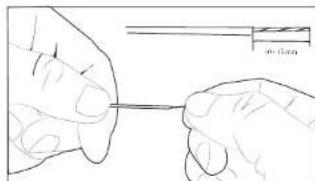
natural_image
Illustration of two hands holding a thin wire with a small inset showing a wire or filament (no text or symbols)natural_image
Simple line drawing of two cars on a horizontal line, no text or symbols presentnatural_image
Illustration of a lawn mower under rain with a cloud, showing the blade and tread (no text or symbols)ČIŠTĚNÍ / ÚDRŽBA

natural_image
3D diagram of a car inside a box, showing internal components (no text or symbols)ČIŠTĚNÍ / ÚDRŽBA
Příprava na jaro
natural_image
Line drawing of a robotic car with spray gun emitting smoke (no text or symbols)ČIŠTĚNÍ / ÚDRŽBA
natural_image
Technical line drawing of a mechanical assembly with hands operating a tool (no text or symbols visible)natural_image
Technical line drawing of a bolt and nut assembly (no text or symbols)ČIŠTĚNÍ / ÚDRŽBA
natural_image
Technical line drawing of a mechanical assembly with a central circular component and a handle (no text or symbols)natural_image
Technical line drawing of a mechanical device showing internal components and a close-up view of a small vehicle (no text or symbols present)RoHS Directive 2011/65/EU
WEEE Directive (2012/19/EU)
Roland Huelon
Podpis:
Misto: Willich
RoHS Directive 2011/65/EU
WEEE Directive (2012/19/EU)

Podpis:
Místo: Saint Cyr Sur Loire
Jméno: Rodolphe Dubois
Generalni reditel
Datum: 2021. 05. 18
SUMEC France
natural_image
Line drawing of a hand operating a mounted robotic lawn mower (no text or symbols)natural_image
Technical line drawing of a mechanical device with gears and shaft (no text or symbols)natural_image
Illustration of a tree crossing a wet concrete path with a lightning bolt, no text or symbols presentObstuga urządzenia:

natural_image
Simple line drawing of a rectangular object with a circular base and a small inset image, on a dotted grid background (no text or symbols)ŚRODKI OSTROŻNOŚCI ŚRODKI OSTROŻN
natural_image
Top-down diagram of a vehicle layout with two cars and directional arrows on a dotted grid background (no text or symbols)ŚRODKI OSTROŻNOŚCI ŚRODKI OSTROŻN
natural_image
Technical line drawing of a mechanical device with open lid and internal components (no text or symbols)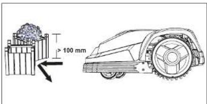
Drzewa
natural_image
Silhouette of a tree with directional arrows indicating movement or motion (no text or symbols)Kamienie
natural_image
Diagram showing a robotic car with a cross symbol indicating collision or failure, alongside a separate 3D object (no text or labels present)Pochyłości
natural_image
Line drawing of a robotic lawn mower with motion lines (no text or symbols)INSTRUKCJA MONTAŻU INSTRUKCJA MON
Rabaty kwiatowe
natural_image
Diagram of a circular structure with radial arrows indicating flow or movement, surrounded by floral patterns and a textured surface (no text or symbols)natural_image
Technical line drawings of three electronic components: a coiled cable, a coiled wire, and a rectangular device with internal structure (no text or symbols)
natural_image
Technical line drawing of a mechanical component with a tool inserted (no text or symbols)
natural_image
Illustration of two hands holding a thin wire with a small inset showing a wire or filament (no text or symbols)natural_image
Simple line drawing of two vehicles, one above and one below, with no text or symbols.natural_image
Diagram showing a lawn mower, rain cloud, and treadmill with an arrow indicating motion (no text or symbols)natural_image
3D diagram of a car inside a rectangular box, showing internal components (no text or symbols)natural_image
Line drawing of a robotic car with spray gun and fan (no text or symbols)CZYSZCZENIE/KONSERWACJA CZYSZCZENIE
Czyszczenie spodu
natural_image
Technical line drawing of a mechanical assembly with hands operating a tool (no text or symbols visible)natural_image
Technical line drawing of a bolt and plate assembly (no text or symbols)
natural_image
Technical line drawing of a mechanical assembly with no visible text or symbolsnatural_image
Technical line drawing of a mechanical assembly with exploded view and component detail (no text or labels)RoHS Directive 2011/65/EU
WEEE Directive (2012/19/EU)

Podpis:
Miasto: Willich
RoHS Directive 2011/65/EU
WEEE Directive (2012/19/EU)
Podpis
Miasto: Saint Cyr Sur Loire