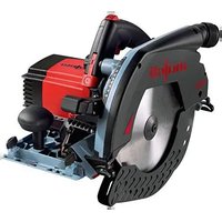
K85Ec - Saw Mafell - Free user manual and instructions
Find the device manual for free K85Ec Mafell in PDF.


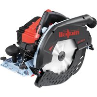
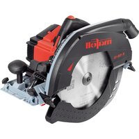
| Product type | Portable circular saw |
| Brand | Mafell |
| Model | K85Ec |
| Dimensions (L x W x H) | 270 x 414 x 305 mm |
| Weight (without cable or parallel guide) | 6.7 kg |
| Rated voltage | 230 V AC |
| Mains frequency | 50 Hz |
| Input power in continuous operation | 2300 W |
| Current consumption in continuous operation | 10.8 A |
| No-load speed (adjustable) | 2250 - 4400 min⁻¹ |
| Depth of cut (0°/30°/45°/60°) | 88 / 75 / 61 / 44 mm |
| Saw unit tilt | 0° to 60° |
| Max/min blade diameter | 237 / 220 mm |
| Blade bore | 30 mm |
| Extraction sleeve diameter | 35 mm |
| Protection class | II |
| Safety devices | Fixed and moving protective hood, riving knife, blade brake, switch lockout |
| Standard equipment | Carbide blade 237 mm 12 teeth, riving knife, parallel guide, service tool, transport case (depending on reference) |
| Extraction connection | Diameter 35 mm, air speed ≥ 20 m/s |
| Maintenance | Regular cleaning, lubrication with MAFELL special grease ref. 049040 |
| Manufacturer warranty | Use only original MAFELL spare parts and accessories |
Frequently Asked Questions - K85Ec Mafell
User questions about K85Ec Mafell
0 question about this device. Answer the ones you know or ask your own.
Ask a new question about this device
Download the instructions for your Saw in PDF format for free! Find your manual K85Ec - Mafell and take your electronic device back in hand. On this page are published all the documents necessary for the use of your device. K85Ec by Mafell.
USER MANUAL K85Ec Mafell
Please read all safety instructions and directions. Failure to comply with the safety instructions and directions can cause electric shock, fire and/or serious injuries. Please retain all safety instructions and directions for future reference.
AVERTISSEMENT
natural_image
Close-up of a black electric vehicle charging plug with handle and cable (no visible text or symbols)MAF02297/a
GB - EC Declaration of Conformity
We herewith confirm that the machine K 85 Ec complies with the EU directives quoted. The standards listed were used for design and construction. Empowered person for the configuration of the technical documents: Mafell AG
GB · EC Declaration of Conformity
We herewith confirm that the machine KSS 80 Ec/370 compiles with the EU directives quoted. The standards listed were used for design and construction. Empowered person for the configuration of the technical documents: Mafell AG
$$ _ {W A} = 3, 0 \mathrm{dB(A)} $$
| 1 | Signs and symbols | 20 |
| 2 | Product information | 20 |
| 2.1 | Manufacturer's data | 20 |
| 2.2 | Machine identification | 20 |
| 2.3 | Technical data | 21 |
| 2.4 | Emissions | 22 |
| 2.5 | Scope of supply | 22 |
| 2.6 | Safety devices | 23 |
| 2.7 | Use according to intended purpose | 23 |
| 2.8 | Residual risks | 23 |
| 3 | Safety instructions | 23 |
| 4 | Setting / adjustment | 26 |
| 4.1 | Mains connection | 26 |
| 4.2 | Chip extraction | 26 |
| 4.3 | Saw blade selection | 26 |
| 4.4 | Saw blade change | 26 |
| 4.5 | Riving knife/splitter | 26 |
| 4.6 | Laying the connection cable | 27 |
| 5 | Operation | 27 |
| 5.1 | Initial operation | 27 |
| 5.2 | Switching on and off | 27 |
| 5.3 | Cutting depth adjustment | 27 |
| 5.4 | Setting for bevel cuts | 28 |
| 5.5 | Plunge cuts | 28 |
| 5.6 | Sawing according to tracings | 28 |
| 5.7 | Sawing with the parallel stop | 28 |
| 5.8 | Working with the roller edge guide | 29 |
| 6 | Service and maintenance | 29 |
| 6.1 | Storage | 29 |
| 7 | Troubleshooting | 29 |
| 8 | Optional accessories | 31 |
| 9 | Exploded drawing and spare parts list | 31 |
1 Signs and symbols

This symbol is found in all places where you will find information for your safety.
Non-compliance with these instructions may result in very serious injuries.
This symbol indicates a potentially hazardous situation.
If this situation is not avoided, the product or objects in its vicinity may get damaged.

This symbol indicates tips for the user and other useful information.
2 Product information
K 85 Ec: Art.-No. 918202, 918230, 918231, 918232, 918235, 91C601, 91C620
KSS 80 Ec 370: Art.-No. 918501, 918520, 918521, 918522, 918525
2.1 Manufacturer's data
MAFELL AG, Beffendorfer Straße 4, D-78727 Oberndorf / Neckar, Phone +49 (0)7423/812-0, Fax +49 (0)7423/812-218, e-mail: mafell@mafell.de
2.2 Machine identification
All details required for machine identification are available on the attached rating plate.

Protection class II

CE symbol to document compliance with the basic safety and health requirements according to Appendix I of the Machinery Directive.
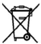
For EU countries only
Do not dispose of electric tools together with household waste material!
In accordance with the European directive 2002/96/EC on waste electrical and electronic equipment and transposition into national law, obsolete electrical tools must be collected separately and recycled in an environmentally-compatible manner.

To reduce the risk of injury, please read the operating instructions.
2.3 Technical data
K 85 cc
Operating voltage
Mains frequency
Input power continuous operation
Power consumption continuous operation
Speed during idling
Cutting depth 0 /30 /45 /60
Tilting saw unit
Saw blade diameter max/min
Saw blade base body thickness
Tool cutting width
Saw blade mounting hole
Hose connector diameter
Weight without mains cable, without parallel guide fence
Dimensions (W x L x H)
230 V AC 110 V AC 120 V AC
50 Hz 50 Hz 60 Hz
2300 W 2300 W 2300 W
10.8 A 17 A 17 A
2250 - 4400 rpm
88/75/61/44 mm (3.46/2.95/2.40/1.73 in.)
0^ - 60^
237/220 mm (9.33 / 8.66 in.)
2.0 mm (0.08 in.)
2.5 mm (0.08 in.)
30 mm (0.08 in.)
35 mm (0.08 in.)
6.7 kg (14.77 lbs)
270 x 414 x 305 mm
(10.63 x 16.30 x 12.01 inches)
KSS 80 Ec 370
Operating voltage
Mains frequency
Input power continuous operation
Power consumption continuous operation
Speed during idling
Cutting depth 0°/30°/45°/60°
Tilting saw unit
Saw blade diameter max/min
Saw blade base body thickness
Tool cutting width
Saw blade mounting hole
Hose connector diameter
Weight without mains cable, without parallel guide fence
Dimensions (W x L x H)
230 V AC 110 V AC 120 V AC
50 Hz 50 Hz 60 Hz
2300 W 2300 W 2300 W
10.8 A 17 A 17 A
2250 - 4400 rpm
88/75/61/44 mm (3.46/2.95/2.40/1.73 in.)
0^ - 60^
237/220 mm (9.33 / 8.66 in.)
2.0 mm (0.08 in.)
2.5 mm (0.1 in.)
30 mm (1.18 in.)
35 mm (1.38 in.)
7.3 kg (16.09 lbs)
270 x 414 x 305 mm
(10.63 x 16.30 x 12.01 inches)
as cross-cutting system
Cutting depth 0°/30°/45°/60°
Cutting length at 80 mm (3.15 in.) workpiece thickness
Weight with guiding device, without mains cable
Dimensions incl. guiding device (W x L x H)
82/69/55/38 mm (3.23/2.72/2.16/1.50 in.)
370 mm (0.08 in.)
8.3 kg (18.30 lbs)
295 x 810 x 305 mm
(11.61 x 31.89 x 12.01 inches)
2.4 Emissions
The declared noise emission values have been measured in accordance with EN 62841-1 and EN 62841-2-5 and may be used for comparing the tool with another and also in a preliminary assessment of exposure.

Danger
The noise emissions during actual use of the power tool can differ from the declared values depending on the ways in which the tool is used especially what kind of workpiece is processed.
Always wear hearing protection, even when the power tool is running idle in addition to the trigger time!
2.4.1 Noise emission specifications
Noise emission values determined according to EN 62841-1 and EN 62841-2-5:
Sound pressure level
$$ \mathrm{L} _ {\mathrm{PA}} = 9 4 \mathrm{dB(A)} $$
Uncertainty K
$$ _ {\mathrm{PA}} = 3, 0 \mathrm{dB(A)} $$
Sound power level L
$$ _ {P A} = 1 0 2 \mathrm{dB(A)} $$
Uncertainty
$$ \mathrm{K} _ {\mathrm{PA}} = 3, 0 \mathrm{dB(A)} $$
The noise measurement was recorded using the saw blade included in the standard equipment.
2.4.2 Vibration specifications
The typical hand-arm vibration is less than 2.5 m/s ^4 .
2.5 Scope of supply
Portable circular saw K85 Ec complete with:
1 carbide-tipped circular saw blade ∅ 237 mm (9 21/64 in.), 12 teeth
1 riving knife / splitter (thickness 2.0 mm / 5/64 in.)
1 parallel stop for item No. 918202, 918230, 918231, 918232, 918235
1 service tool in bracket on the machine
1 operating manual
1 folder "Safety Instructions"
1 carrying case for item No. 918202, 918230, 918231, 918232, 918235
Cross-Cutting System KSS80Ec/370 complete with:
1 carbide-tipped circular saw blade ∅ 237 mm (6 1/4 in.), 12 teeth
1 riving knife / splitter (thickness 2.0 mm/3.32 in.)
1 parallel stop
1 service tool in bracket on the machine
1 operating manual
1 folder "Safety Instructions"
1 Guiding device L (max. cut length 370 mm)
2.6 Safety devices
Danger
These devices are required for the machine's safe operation and may not be removed or rendered inoperative.
Before operating the machine, check the safety devices for function and possible damage. Do not use the machine with missing or ineffective safety devices.
The machine is equipped with the following safety devices:
- Upper stationary saw guard
- Lower retractable saw guard
- Large base plate
- Handles
- Riving knife / splitter
- Index mechanism and brake
- Hose connector
2.7 Use according to intended purpose
The K 85 Ec / KSS 80 Ec is exclusively suited for longitudinal and cross cutting of solid wood.
Panel materials such as chip board, core board and medium density fibre board can also be processed. Use approved saw blades according to EN 847-1.
Processing wood fibre insulation materials and synthetic materials (polystyrene) is also possible.
Any other use than described above is not permissible. The manufacturer cannot be held liable for any damage arising from such other use.
So as to use the machine as intended, comply with the operating, maintenance and repair instructions specified by Mafell.
2.8 Residual risks

Danger
Even if used in accordance with its intended purpose and despite conforming with the safety instructions, residual risks caused by the intended use that can lead to health consequences will always remain.
- Touching the saw blade in the vicinity of the starting aperture below the base plate.
- Touching the part of the saw blade that protrudes below the workpiece when cutting.
- Touching of turning parts from the side: saw blade, clamping flange and flange screw.
- Machine backlash if the blade gets stuck in the workpiece.
- Breakage of the saw blade and risk of the blade or pieces of the blade being hurled away.
- Touching live parts with the housing open and the mains plug not removed.
- Hearing can be impaired when working for long periods without ear protectors.
- Emission of harmful wood dusts during longer operation without extraction.
3 Safety instructions
Danger
Always observe the following safety instructions and the safety regulations applicable in the respective country of use! Also read the safety instructions in the enclosed booklet "Safety instructions".
General instructions:
- Children and adolescents must not operate this machine. This rule does not apply to young persons receiving training and being supervised by an expert.
-
Never work without the protection devices prescribed for the respective operating sequence and do not make any changes to the machine that could impair safety.
-
When operating the machine outdoors, use of an earth-leakage circuit-breaker is recommended.
- Damaged cables or plugs must be immediately replaced. Replacement may only be carried out by Mafell or an authorised MAFELL service workshop in order to avoid safety hazards.
- Avoid sharp bends in the cable. Especially when transporting and storing the machine, do not wind the cable around the machine.
Do not use:
- Cracked and misshapen saw blades.
- Saw blades made of high speed steel (HSS saw blades).
- Blunt saw blades as they impose an excessive load on the motor.
- Saw blades with a base body with a thickness greater than, or a cutting width (setting) less than, the thickness of the riving knife / splitter.
- Saw blades which are not suitable for the saw blade's idling speed.
- Grinding discs
Instructions on the use of personal protective equipment:
- Always wear ear protectors during work.
- Always where a dust mark during work.
- Always wear protective goggles during work.
Instructions on operation:
Sawing method

Danger
- Keep hands away from cutting area and the blade. Keep your second hand on auxiliary handle, or motor housing. If both hands are holding the saw, they cannot be cut by the blade.
- Do not reach underneath the workpiece. The guard cannot protect you from the blade below the workpiece.
-
Adjust the cutting depth to the thickness of the workpiece. Less than a full tooth of the blade teeth should be visible below the workpiece.
-
Never hold the workpiece in your hands or across your leg while cutting. Secure the workpiece to a stable platform. It is important to support the work properly to minimise body exposure, blade binding, or loss of control.
- Hold the power tool by insulated gripping surfaces, when performing an operation where the cutting tool may contact hidden wiring or its own cord. Contact with a "live" wire will also make exposed metal parts of the power tool "live" and could give the operator an electric shock.
- When ripping, always use a rip fence or straight edge guide. This improves the accuracy of cut and reduces the chance of blade binding.
- Always use blades with correct size and shape (diamond versus round) of arbour holes. Blades that do not match the mounting hardware of the saw will run off-centre, causing loss of control.
- Never use damaged or incorrect blade washers or bolt. The blade washers and bolt were specially designed for your saw, for optimum performance and safety of operation.
Kickback causes and related warnings
- kickback is a sudden reaction to a pinched, jammed or misaligned saw blade, causing an uncontrolled saw to lift up and out of the workpiece toward the operator;
- When the blade is pinched or jammed tightly by the kerf closing down, the blade stalls and the motor reaction drives the unit rapidly back toward the operator;
- if the blade becomes twisted or misaligned in the cut, the teeth at the back edge of the blade can dig into the top surface of the wood causing the blade to climb out of the kerf and jump back toward the operator.
Kickback is the result of saw misuse and/or incorrect operating procedures or conditions and can be avoided by taking proper precautions as given below.
- Maintain a firm grip with both hands on the saw and position your arms to resist kickback forces. Position your body to either side of the blade, but not in line with the blade. Kickback could cause the saw to jump backwards, but kickback forces can be controlled by the operator, if proper precautions are taken.
- When blade is binding, or when interrupting a cut for any reason, release the trigger and hold the saw motionless in the material until the blade comes to a complete stop. Never attempt to remove the saw from the work or pull the saw backward while the blade is in motion or kickback may occur. Investigate and take corrective actions to eliminate the cause of blade binding.
- When restarting a saw in the workpiece, centre the saw blade in the kerf so that the saw teeth are not engaged into the material. If a saw blade binds, it may walk up or kickback from the workpiece as the saw is restarted.
- Support large panels to minimise the risk of blade pinching and kickback. Large panels tend to sag under their own weight. Supports must be placed under the panel on both sides, near the line of cut and near the edge of the panel.
- Do not use dull or damaged blades. Unsharpened or improperly set blades produce narrow kerf causing excessive friction, blade binding and kickback.
- Blade depth and bevel adjusting locking levers must be tight and secure before making the cut. If blade adjustment shifts while cutting, it may cause binding and kickback.
- Use extra caution when sawing into existing walls or other blind areas. The protruding blade may cut objects that can cause kickback.
Lower guard function
- Check the lower guard for proper closing before each use. Do not operate the saw if the lower guard does not move freely and close instantly. Never clamp or tie the lower guard into the open position. If the saw is accidentally dropped, the lower guard may be bent. Raise the lower guard with the retracting handle and make sure it moves freely and does not touch the blade or any other part, in all angles and depths of cut.
-
Check the operation of the lower guard spring. If the guard and the spring are not operating properly, they must be serviced before use. Lower guard may operate sluggishly due to damaged parts, gummy deposits, or a build-up of debris.
-
The lower guard may be retracted manually only for special cuts such as "plunge cuts" and "compound cuts". Raise the lower guard by the retracting handle and as soon as the blade enters the material, the lower guard must be released. For all other sawing, the lower guard should operate automatically.
- Always observe that the lower guard is covering the blade before placing the saw down on bench or floor. An unprotected, coasting blade will cause the saw to walk backwards, cutting whatever is in its path. Be aware of the time it takes for the blade to stop after switch is released.
Riving knife function
- Use the appropriate saw blade for the riving knife. For the riving knife to function, the body of the blade must be thinner than the riving knife and the cutting width of the blade must be wider than the thickness of the riving knife.
- Adjust the riving knife as described in this instruction manual. Incorrect spacing, positioning and alignment can make the riving knife ineffective in preventing kickback.
- Always use the riving knife except when plunge cutting. The riving knife must be replaced after plunge cutting. The riving knife causes interference during plunge cutting and can create kickback.
- For the riving knife to work, it must be engaged in the workpiece. The riving knife is ineffective in preventing kickback during short cuts.
- Do not operate the saw if the riving knife is bent Even a light interference can slow the closing rate of a guard.
Instructions on service and maintenance:
- Regularly cleaning the machine, especially the adjusting devices and guides, constitutes an important safety factor.
- Only original MAFELL spare parts and accessories may be used. Otherwise the manufacturer will not accept any warranty claims and cannot be held liable.
4 Setting / adjustment
4.1 Mains connection
Prior to commissioning make sure that the mains voltage complies with the operating voltage stated on the machine's rating plate.
4.2 Chip extraction

Danger
Substances that are harmful to health must be taken up with an M-suction device.
Connect the machine to a suitable external dust extractor during all work generating a considerable amount of dust. The air velocity must be at least 20 m/s (65.6 ft / sec.).
The internal diameter of hose connector 3 (Fig. 1) is 35 mm (1 3/8 in.).
4.3 Saw blade selection
Use a sharp tool to obtain a good cut quality and select a tool from the following list according to material and application:
For cuts along and across the grain in soft or hard wood:
- Circular saw blade carbide ∅ 237 x 2.5 x 30 mm, 24 teeth
For cuts especially along the grain in soft or hard wood:
- Circular saw blade carbide ∅ 237 x 2.5 x 30 mm, 12 teeth
For cuts especially across the grain in soft or hard wood:
- Circular saw blade carbide ∅ 237 x 2.5 x 30 mm, 56 teeth
Cutting of wood fibre insulation materials:
- Circular saw blade carbide ∅ 237 x 2.5 x 30 mm, 56 teeth
Cutting of synthetic materials (polystyrene):
- Circular saw blade carbide ∅ 237 x 2.5 x 30 mm, 24 teeth
4.4 Saw blade change
Danger
Pull the power plug during all service work.
- Press the push-button 2 (Fig. 2) and pull the locking lever 19 upwards. Now the saw shaft is locked in position and the gearshift lever locked. You can lock the retractable saw guard in an open position with the aid of the pre-feed lever 1 (Fig. 2) or manually to make the tool change easier.
- Using the Allen key 5 (bracket Fig. 2), release the flange screw 18 (Fig. 3) counter clockwise. Now remove both the screw and the front clamping flange 12.
- You can now remove the saw blade.
- The clamping flanges must be free of adhering parts.
- Pay attention to the sense of rotation when inserting the saw blade.
- Afterwards, push on the clamping flange, apply the flange screw and tighten it by turning it clockwise.
- Close the retractable saw guard. To do so, press the locking lever 19 (Fig. 2) downwards.
4.5 Riving knife/splitter

Danger
Pull the power plug during all service work.
The riving knife / splitter 15 (Fig. 3) prevents the saw blade from jamming during longitudinal cutting. The correct distance to the saw blade is shown in (Fig. 4).
- For adjustment purposes, release the screw 4 (Fig. 3) with the Allen key 5 that is included in the supply (Fig. 2)
- Adjust the riving knife/splitter by moving it in its longitudinal groove and retighten the screw afterwards.
4.6 Laying the connection cable

Danger
While working, pay attention to how the connecting cable is laid. A poorly laid connecting cable can impair safety functions and working functions and come into contact with the tool.
How to lay the cable is shown in Fig. 5 by way of example.
Lead the connecting cable away from the machine in the direction of the cable sleeve. Always keep the connecting cable as far away as possible from the working tool. For support, use the Velcro fastener on the extraction connection.
5 Operation
5.1 Initial operation
Personnel entrusted to work with the machine must be made aware of the operating instructions, calling particular attention to the chapter "Safety instructions".
5.2 Switching on and off
- Switching on: Press the switch-on lock 7 (Fig. 2) forward to unlock it. Then, with the switch-on lock depressed, press gearshift lever 8.
As this is a switch without locking device, the machine will only run for as long as this gearshift lever is pressed.
The built-in electronic system provides for jerk-free acceleration when the machine is switched on and under load readjusts the speed to the fixed setting.
In addition, this electronic system adjusts the motor down in case of overload, i.e. the saw blade will stop.
Switch the machine off then. Then switch the machine on again and continue sawing at a reduced feed speed.
The setting wheel 20 (Fig. 2) can be used to adjust the tool speed in a continuously variable manner between 2250 and 4400 rpm.
| Level Speed rpm | |
| 1 2250 | |
| 2 2680 | |
| 3 | 3110 |
| 4 | 3540 |
| 5 3970 | |
| 6 4400 |
Material groups
- Hardwood, softwood, plywood - Level: 4 - 6
- Coated panel materials - Level: 4 - 6
- Soft fibre - Level: 6
- Switching off: To switch off, release the gearshift lever 8. The built-in automatic brake limits the saw blade slowing time to approx. 5 s. The switch-on lock automatically takes effect again and secures the portable circular saw against accidental switch-on.
5.3 Cutting depth adjustment
The cutting depth is continuously variable between 0 and 88 mm.
Proceed as follows:
- Press the push-button 11 (Fig. 1) and adjust the cutting depth with the plunge lever 6.
- The cutting depth can be read off scale 13 on the cover. The surface of plunge lever 6 with the red background serves as indicator.

Always set the cutting depth approx. 2 to 5 mm (5/64 to 13/64 in.) larger than the material thickness to be cut.
5.4 Setting for bevel cuts
For bevel cuts, the saw unit can be set to any angle between 0^ and 60^ .
- In order to incline it, bring the machine into home position and support it such that it is possible to tilt the saw unit.
• Unfasten the wing nut 10 (Fig. 2) - Adjust the angle according to the scale on the segment for tilting.
• Afterwards, tighten the wing bolt 10.
5.5 Plunge cuts

Danger
Risk of backlash during plunge cuts! Prior to plunging, place the machine with the rear edge of its base plate against a limit stop fastened on the workpiece. Keep a firm hold on the machine handle during plunging and push the saw lightly forward!
- Press the push-button 11 (Fig. 1) and put the machine in the topmost position with plunge lever 6.
- Completely open the retractable saw guard with the pre-feed lever 1 (Fig. 2), so that the machine can be placed onto the workpiece to be processed. The saw blade is now freely suspended above the material and can be aligned with the marking.
- Switch on the machine and press the plunge lever 6 (Fig. 1) downwards. This causes the saw blade to plunge vertically into the workpiece. The plunging depth can be read from scale 13. The riving knife / splitter swings up and away when the blade enters the workpiece. As soon as the slit behind the saw blade is cleared during the forward motion of the machine, the riving knife reverts to its normal position.

In case of repetitive plunge cuts of the same depth, the plunging depth can be preset.
Proceed as follows:
- Set the machine to the desired cutting depth.
- Open the clamping screw 14 (Fig. 2) and set the stop bar 16 downwards up to the limit stop.
- Retighten the clamping screw. After completion of the plunge work, set the stop bar into the top position.
5.6 Sawing according to tracings
The pivoting part is equipped with a tracing edge for 0^ - 60^ . This tracing edge corresponds to the saw blade's inside. For bevel cuts, the tracing can be viewed through the opening on the left-hand side of the upper saw guard.
- Hold the machine by its handles and place the front part of its base plate onto the workpiece.
- Switch on the portable circular saw (see chapter 5.2) and slide the machine evenly forward in the direction of the cut.
- When the cut is completed, switch off the saw by releasing the switch trigger 8 (Fig. 2)
5.7 Sawing with the parallel stop
The parallel stop 17 (Fig. 2) serves to cut parallel to an already existing edge. The limit stop can be attached to the left or right of the machine. The cutting range on the right-hand side amounts to 40 - 200 mm (1 37/64 - 7 7/8 in.) and on the left-hand side to 195 - 405 mm (7 43/64 - 15 15/16 in.). In the range 195 - 260 mm (7 43/64 - 10 15/64 in.), the machine must be set approx. 10 mm (25/64 in.) to the top, so that the machine can be pushed under the motor casing.
- You can adjust the cutting width after releasing the wing screws 9 (Fig. 2) by moving the limit stop accordingly and afterwards retightening the wing screws.
In addition, by simply turning it around (guide face for the workpiece edge points upwards), the parallel stop can also be used as double support to improve guidance of the portable circular saw. Now the machine can be guided along a lath that is fastened on the workpiece.
5.8 Working with the roller edge guide
The roller edge guide serves to work parallel to an already existing edge. The limit stop can be attached to the left or right of the machine. The cutting range on the right-hand side amounts to approx. 12 - 48 mm (15/32 - 1 57/64 in.) and on the left-hand side to approx. 40 - 280 mm (1 37/64 - 11 15/64 in.).
- You can adjust the cutting width after releasing the wing screws 9 (Fig. 2) by moving the limit stop accordingly and afterwards retightening the wing screws.
6 Service and maintenance

Danger
Pull the power plug during all service work.
MAFELL machines are designed to be low in maintenance.
The ball bearings used are greased for life. When the machine has been in operation for a longer period of time, we recommend to hand the machine in at an authorised MAFELL customer service shop for inspection.
Only use our special grease, order No. 049040 (1 kg tin) for all greasing points.
6.1 Storage
Clean the machine thoroughly if the machine is not used for a longer period of time. Spray blank metal parts with a rust-proofing agent.
7 Troubleshooting

Danger
Determining the causes for existing defects and eliminating these always requires increased attention and caution. Pull the mains plug beforehand!
Some of the most frequent defects and their causes are listed in the following chart. In case of other defects, please contact your dealer or the MAFELL customer service directly.
| Defect | Cause | Elimination |
| Machine cannot be switched on | No mains voltage or mains voltage too low | Have power supply checked by an electrician |
| Mains fuse defective | Have fuse replaced by an electrician | |
| Carbon brushes worn | Take the machine to a MAFELL customer service shop | |
| Machine stops while cutting is in process | Mains failure | Have mains-side pre-fuses checked by an electrician |
| Machine overloaded Reduce feed speed | ||
| Carbon brushes worn | Take the machine to a MAFELL customer service shop | |
| Saw blade jams as the machine is advanced | Feed rate too fast | Reduce feed speed |
| Blunt saw blade | Release the switch immediately. Remove the machine from the workpiece and replace the saw blade | |
| Tension in the workpiece | Heightened caution during sawing, risk of backlash increases. | |
| Poor machine guidance (for example due to free-hand guidance) | Use parallel guide fence | |
| Uneven workpiece surface | Straighten the surface | |
| Saw blade vibrates in the work piece | Saw blade not correctly adjusted | Retighten saw blade |
| Work piece not fastened | Fasten work piece with clamps | |
| Saw blade stops - motor continues to turn | Saw blade not correctly fastened | Retighten saw blade |
| Burn marks on the cut surfaces | The saw blade used is unsuitable for the task or blunt | Replace saw blade |
| Chip ejection blocked | Wood is too damp | Clean chip ejection |
| Extended operation without extraction | Connect machine to an external extraction, e.g. portable dust extractor | |
| Lower mobile protective cover does not close or closes only slowly | Chips and pieces of wood in the bottom mobile protective cover | Remove chips and pieces of wood |
8 Optional accessories
- Saw blade carbide ∅ 237 x 2.5 x 30 mm, 12 teeth (longitudinal cut) Order No. 092590
- Saw blade carbide ∅ 237 x 2.5 x 30 mm, 24 teeth (longitudinal and cross cuts) Order No. 092591
- Saw blade carbide ∅ 237 x 2.5 x 30 mm, 56 teeth (cross cut) Order No. 092592
- Guide rail F80, 800 mm long Order No. 204380
- Guide rail F110, 1100 mm long Order No. 204381
- Guide rail F160, 1600 mm long Order No. 204365
- Guide rail F210, 2100 mm long Order No. 204382
- Guide rail F310, 3100 mm long Order No. 204383
- Sliding bevel segment F-WA Order No. 205357
- Accessories for guide rail:
- Screw clamp F-SZ180MM (2 x) Order No. 207770
- Connecting piece F-VS Order No. 204363
- Rail bag F160 Order No. 204626
- Rail bag kit F80/160 with sliding bevel segment consisting of: F80 + F160 + Order No. 204749 connecting piece + sliding bevel + 2 screw clamps + rail bag
- Rail bag kit F160/160 consisting of: 2 x F160 + connecting piece + 2 screw Order No. 204805 clamps + rail bag
- Parallel stop, K85-PA. Order No. 205323
- Roller edge guide K85-UA Order No. 205166
- guiding device L Order No. 208171
- Aerofix suction-clamping-system F-AF 1 consisting of: Rail 1.3 m, adapter for Order No. 204770 top and bottom, flexible hose
- Flexible hose FXS-L, length 3.2 m Order No. 205276
- End caps packed F-EK Order No. 205400
- Adhesive profile packed F-HP 6.8M Order No. 204376
- Splinter guard packed F-SS 3.4M Order No. 204375
- Carrying case L- MAX Order No. 095170
9 Exploded drawing and spare parts list
The corresponding information in respect of spare parts can be found on our homepage: www.mafell.com
Sommaire
$$ K _ {P A} = 3, 0 \mathrm{dB(A)} $$
$$ K _ {P A} = 3, 0 \mathrm{dB(A)} $$
Lydeffektniveau L
$$ _ {W A} = 1 0 2 \mathrm{dB(A)} $$
Usikkerhed K
$$ _ {W A} = 3, 0 \mathrm{dB(A)} $$
$$ K _ {P A} = 3, 0 \mathrm{dB(A)} $$
Raven zvočne moči L
$$ _ {P A} = 1 0 2 \mathrm{dB(A)} $$
Negotovost K
$$ _ {P A} = 3, 0 \mathrm{dB(A)} $$
Neistota K _WA = 3,0 dB (A)
MAFELL AG
Beffendorfer Straße 4, D-78727 Oberndorf / Neckar
Telefon +49 (0)7423/812-0
Internet:
E-Mail:
Fax +49 (0)7423/812-218
www.mafell.de
mafell@mafell.de
- AVERTISSEMENT
- GB - EC Declaration of Conformity
- GB · EC Declaration of Conformity
- Signs and symbols
- Product information
- Manufacturer's data
- Machine identification
- Technical data
- K 85 cc
- KSS 80 Ec 370
- as cross-cutting system
- Emissions
- Danger
- Noise emission specifications
- Vibration specifications
- Scope of supply
- Safety devices
- Use according to intended purpose
- Residual risks
- Safety instructions
- General instructions:
- Do not use:
- Instructions on the use of personal protective equipment:
- Instructions on operation:
- Sawing method
- Kickback causes and related warnings
- Lower guard function
- Riving knife function
- Instructions on service and maintenance:
- Setting / adjustment
- Mains connection
- Chip extraction
- Saw blade selection
- For cuts along and across the grain in soft or hard wood:
- For cuts especially along the grain in soft or hard wood:
- For cuts especially across the grain in soft or hard wood:
- Cutting of wood fibre insulation materials:
- Cutting of synthetic materials (polystyrene):
- Saw blade change
- Riving knife/splitter
- Laying the connection cable
- Operation
- Initial operation
- Switching on and off
- Material groups
- Cutting depth adjustment
- Proceed as follows:
- Setting for bevel cuts
- Plunge cuts
- Sawing according to tracings
- Sawing with the parallel stop
- Working with the roller edge guide
- Service and maintenance
- Storage
- Troubleshooting
- Optional accessories
- Exploded drawing and spare parts list
- Sommaire
Brand : Mafell
Model : K85Ec
Category : Saw