OurAir TK 850 - Air purifier MANN+HUMMEL - Free user manual and instructions
Find the device manual for free OurAir TK 850 MANN+HUMMEL in PDF.

User questions about OurAir TK 850 MANN+HUMMEL
0 question about this device. Answer the ones you know or ask your own.
Ask a new question about this device
Download the instructions for your Air purifier in PDF format for free! Find your manual OurAir TK 850 - MANN+HUMMEL and take your electronic device back in hand. On this page are published all the documents necessary for the use of your device. OurAir TK 850 by MANN+HUMMEL.
USER MANUAL OurAir TK 850 MANN+HUMMEL
Original Operating Manual
text_image
MANN+ HUMMEL Vickers Air GmbH & Co. OHG Einzetholder Weg 14-15 D-23649 Sprachholol Indoor Air Purifier- OurAir TK 850 Serial number: Part number: Volume: Frequency: Power: Current: Weight Manufacturing dade: YYYY Designed and Engineered in Germany Made in China MANN+ HUMMEL 5 6 7 8 9 10Abb. 1: Tyoenschild
text_image
Technical diagram of a 3D printer or scanner with labeled parts 1, 2, and 3Abu. 3: TK 850 Frontansich
Rückansicht
natural_image
Diagram showing two mechanical components with arrows indicating motion or assembly (no text or symbols)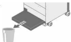
natural_image
Illustration of a cart with a bucket being inserted, no text or symbols present
text_image
Diagram showing an eye interacting with a device, with an arrow pointing to the screen and a box nearby.natural_image
Diagram showing two mechanical components with a triangular load and an arrow indicating direction (no text or symbols)natural_image
Diagram showing mechanical components with angle标注 (90°), no readable text or symbols present
ACHTUNG!
text_image
Diagram illustrating a mechanical device with numbered components and directional arrows, likely illustrating a process or assembly.
text_image
Diagram illustrating a mechanical or optical setup with labeled components and directional arrows, including a magnified inset showing steps 1, 2, and 3.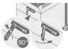
Leuchtmitteltausch
9 LEUCHTMITTELTAUSCH\*
text_image
Diagram illustrating a recycling process with labeled components and directional arrows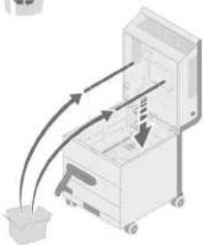
natural_image
Diagram of a mechanical device with arrows indicating motion or force direction (no text or symbols)
text_image
Diagram of a mechanical device with labeled parts and a magnified view showing part 'x4'PflegeLeucht
10 PFLEGE
Original Operating Manual
Leadership in Filtration
MANN+ HUMMEL
Table of contents
Table of contents
Table of contents
1 INTRODUCTION 4
1.1 Vendor and publisher 4
1.2 Means of representat on 4
1.2.1Lists4
1.2.2 Instructions 5
1.2.3 Safety notices 5
1.2.4 Mandatory signs 5
1.2.5 General information
2 SAFETY
2.1 Basic safety instructions
2.2 Intended use
2.3 Non-intended use
2.4. Labeling on the appliance
2.4.1 Type label (example)
3 FUNCTION DESCRIPTION
3.1 General information on indoor air quality
3.2 The purification process described
4 TECHNICAL DATA
4.1 Appliance representation
5 INSTALLATION
5.1 Transport
5.2 Positioning
6 COMMISSIONING
6.1 Special safety instructions
6.11 Electrical requirements
6.12 UV-C light bulbs*
6.1.3 Filter elements
6.2 Power supply 17
7 OPERATION
71 Home screen
7.2 Description of the controls
7.5 PIN code**
7.51 PIN code screen protection**
7.3.2 Charge PIN code**
7.4 Starting the appliance
7.5 Selecting the fan level
7.6 Manually switching the UV-C lamp on
* Applies to models with integrated UV lamps.
^19 Applies to models with PIN code protection
2 - EN EN - 3
7.7 Automatic and manual mode 23
7.71 Manual mode 23
7.7.2 Automatic mode (timer) 23
7.8 Advanced settings 24
7.8.1 Language 24
7.8.2 Date and time 25
7.8.3 Disp ay brightness 25
7.9 Service menu 26
7.9.1 Show the remaining filter service life 26
7.9.2 Confirm filter change 26
7.9.3 Display operating hours 27
7.9.4 Confirm light-bulb replacement ^® 27
7.10 Display device information 27
8 FILTER REPLACEMENT 28
8.1 Special safety instructions 28
8.2 Filter replacement at a glance 29
8.3 Replacing the pre-filter 30
8.4 Replacing the HEPA filter 31
9 LIGHT BULB REPLACEMENT\* 33
9.1 Special safety instructions 33
9.2 Replacing the light bulbs 34
10 CARE 35
10.1 Special safety instructions 35
10.2 Regular maintenance 35
11 SERVICE AND MAINTENANCE 35
11.1 Special safety instructions 35
11.2 Maintenance plan 36
11.3 Re- orderable accessories 36
12 STORAGE 37
12.1 Storing filter elements 37
12.2 Storage 37
13 TROUBLESHOOTING 38
14 DISPOSAL 39
14.1 Environmental protection 39
14.2 Filters 39
14.3 UV-C light bulbs ^4 39
15 DECLARATION OF CONFORMITY 40
* Apolies to models with integrated UV lamps.
1 INTRODUCTION
Thank you for purchasing the MANN+HUMMEL OurAir TK 850 indoor air purifier.
With the integrated HEPA filter element (High Efficiency Particulate Air), your indoor air purifier protects you and the people around you from numerous indoor air pollutants such as particulates, bacteria and aerosol-borne viruses in highly frequented public areas such as schools, conference rooms, dining halls, waiting and reception areas, care homes and production spaces.
In models with integrated UV-C lamps, the HEPA filter element is irradiated with UV-C rays at suitable intervals in order to neutralize pathogens such as bacteria and viruses and to inhibit their growth.
This Operating Manual contains important information regarding the safety, operation and maintenance of the appliance. Please read this Operating Manual carefully. Always keep this Operating Manual and the safety information it contains in the immediate vicinity of your air purifier.
We reserve the right to make technical improvements to the products described in this Operating Manual without notification. We can provide Information on the current status. Further information and support are available from our website at www.mann-hummel.com. You can also contact the point of sale where you purchased the product.
This is the translation of the original Operating Manual. The publisher owns the copyright for this Operating Manual. Reprinting, translation and copying of this document, or extracts of it, requires the explicit written consent of the publisher.
1.1 Vendor and publisher
If you have any questions about your MANN+HUMMEL interior air purifier, please contact us: MANN+HUMMEL Vokes Air GmbH & Co. OHG
Eichenhofer Weg 14-16
45549 Sprockhövel, Germany
Telephone: +49 (0) 7141 98 - 2601
Fax: +49 (0) 7141 98 - 2545
Internet: www.mann-hummel.com
E-mail: support.our.air@mann-hummel.com
Scan the QR code to view the latest version of the operating manual.

1.2 Means of representation
1.2.1 Lists
Lists are shown as indents, as in the following examples:
- Make sure that the air inlet on the appliance is not blocked.
- If possible, distribute a number of appliances around a room so that the air is purified in all areas.
[Non-Text]
IntroductionIntrodu
1.2.2 Instructions
Instructions to be performed in a certain order are numbered, as shown in the following example:
1. Switch off the appliance at the main power switch.
2. Pull the power plug out of the power outlet.
1.2.3 Safety notices
This Operating Manual as well as your OurAir indoor air purifier come with the following safety instructions:

NING: ELECTRICAL VOLTAGE!
Safety information with this symbol indicates a risk to persons from high electrical that can cause serious or even fatal injury.

NING OF HAND INJURY!
Safety information with this symbol indicates a risk to persons from closing mechanical components that can cause minor or moderate injury.

NING: HOT SURFACES!
Safety information with this symbol indicates a risk to persons from touching hot components that could potentially result in minor or moderate injury.

WARNING!
A safety notice with the signal word WARNING! indicates a general personal risk that tentially result in minor or moderate injury.

CAUTION!
A safety notice with the signal word CAUTION! indicates a risk of damage to property.
1.2.4 Mandatory signs

WEAR GOGGLES!
Notes with this symbol indicate that eye protection must be used as part of the protective equipment (PPE).

R RESPIRATORY PROTECTION!
Notes with this symbol indicate that respiratory protection (protection class FFP2 at just be used as part of the personal protective equipment (PPE).

RING SAFETY GLOVES!
Notes with this symbol indicate that safety gloves must be worn as part of the protective equipment (PPE).

R FOOT PROTECTION!
Notes with this symbol indicate that foot protection must be worn as part of the protective equipment (PPE).

R TO THE OPERATING MANUAL!
This symbol indicates that you should read and follow the Operating Manual before g the appliance.
1.2.5 General information

NOTE
This symbol in all the sections of the manual in which the information provided must fully observed to ensure trouble-free and economic operation.
Additional information is marked with this symbol
2 SAFETY
2.1 Basic safety instructions

WARNING!
In an emergency or when replacing electrical components:
- Switch off the appliance at the main power switch and pull the power plug out of the power outlet.
- Do not reconnect a defective appliance to the power supply!
- Please contact our customer service!

WARNING!
To avoid personal injury and damage to property, please follow the guidelines and instructions below.

WARNING!
personal protective equipment (PPE)
Personnel responsible for changing filters, servicing units, or moving units within the y are strongly advised to wear appropriate personal protective equipment (PPE)
and to follow safe work practices in accordance with legal and industrial safety regulations.


6 - EN EN - 7
SafetySafety

TO THE OPERATING MANUAL
Read this Operating Manual carefully before installing / using the appliance and always keep it in the immediate vicinity of the place of installation, or on the appliance itself. Follow the safety information and instructions.
We accept no liability for damage or malfunctions resulting from non-compliance with these operating instructions!
- The air purifier does not remove carbon monoxide (CO) or radon (Rn) and must not be used where accidents have caused combustion and hazardous chemicals.
- Do not operate the appliance with a damaged power cord or plug. If the power cord of the appliance or its plug is damaged, it must be replaced by qualified personnel in order to avoid hazards. Contact the manufacturer or their customer service in this case.
- Do not kink, twist, crush or pull on the power cord. Pull the power plug to unplug the power cord from the power outlet.
- Check the condition of the power cord before use. Damaged cables can cause fatal electric shocks!
- Lay the cable unobstructed in the room. Do not cover the cable with carpets or similar. Do not lay the cord under furniture or appliances. Keep the power cord away from walkways so that no one trips over it.
- Do not operate or position the appliance in potentially explosive areas or rooms. - Keep the appliance away from sources of fire and flammable substances.
- Do not position or operate the appliance near gas appliances, fireplaces, or other heaters.
- Place the appliance upright and secure from tipping on a stable, level, horizontal and dry surface.
- Do not operate or touch the appliance or power plug with wet or clamp hands, otherwise you could receive an electric shock.
- At no time should you allow unauthorized persons or children to operate the appliance.
- Do not expose the appliance to direct water jets. Do not operate it in damp rooms and do not place it there.
- Never push objects or limbs through the air inlet or air outlet grilles!
- Do not cover the appliance during operation and do not place any objects or clothing on L.
- Do not sit or stand on the appliance. Do not use it as a step.
- Koco children and animals away from the appliance. Use the appliance only under supervision
- The appliance may only be operated by persons (including children aged 8 years and older) with limited sensory, mental or physical abilities and by persons unfamiliar with the Operating Manual under the supervision of persons who are responsible for their safety.
- Before operation, check the appliance, the power cord and its plug as well as any accessories for damage. Do not use damaged appliances or parts.
- Protect the appliance and its parts (e.g. power cord, plug, etc.) from damage.
- The power connection must meet the requirements specified in chapter 4 on page 12 - Pull out the power plug before conducting any maintenance or servicing work on the appliance.
- When not in use, switch off the appliance off and unplug the power cord.
- Observe minimum clearances to the appliance. These are available in section 5.2 on page 14.
- Make sure that there are no objects in the air inlet or the outlet area of the appliance before operation.
- Do not block the air inlets or air outlets of the appliance. Insufficient air circulation affects the performance of the appliance.
- Dispose of used and exchanged filter elements with household waste.
- Do not disassemble, repair or modify the appliance without approval from the manufacturer. Unauthorized disassembly or repairs can result in malfunctions and hazards. Unauthorized modification can lead to fire and malfunctions.
- Do not use solvents to clean the product as this will damage the product and may result in electric shock, which can cause personal injury or fire.
- Use only original MANN+HUMMEL spare parts that are intended for this product. Part numbers are available in section 11.3 on page 36.
- Before starting the appliance, make sure that all filter elements are inserted properly. Never operate the appliance without filter elements!
SafetySafety
2.2 Intended use
- The OurAir indoor air purifier is used exclusively for the mechanical filtration of impurities (e.g. particulates, paper and textile microfibres, harmful gases, allergens) and finely dispersed (including virus-carrying) aerosols from the ambient air by air circulation within closed spaces.
- Only operate the appliance if it is in technically perfect condition, taking aspects of safety and risk into account and observing the Operating Manual.
- Only persons familiar with this document are authorized to service the device in accordance with the maintenance intervals specified in these operating instructions.
- The device is designed for use in private and commercial areas (pollution degree 2 according to IEC 60664-1 and IEC 61010-1)".
2.3 Non-intended use

WARNING!
The OurAir indoor air purifier is not a medical product and is not certified as such.
Do not use the appliance in a manner other than that described in this Operating Manual.
- Do not use the appliance if you are unable to comply with the operating conditions.
- Do not place the appliance on a wet or flooded surface.
- Do not place the appliance on an unpaved surface.
- Do not place any objects such as clothing on the appliance.
- Do not operate the appliance outdoors.
- Do not use the appliance to suck in vapours or liquids.
- Do not use the appliance for therapeutic purposes.
- Any operation or use other than that specified in this Operating Manual is not permitted.
Failure to comply will void any liability and warranty claims. - Unauthorized structural changes as well as additions or modifications to the appliance
are prohibited.
2.4 Labelling on the appliance

NOTE
Ensure that all labels on the appliance are in a legible condition.
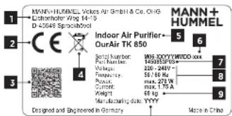
2.4.1 Type label (example)
(1) Manufacturer, address, logo
(2) CE marking
(3) QR code (link on manufacturer website)
(4) Do not dispose of the appliance
in household waste!
(5) Model name
(6) Serial number
(7) Part number
(8) Electrical data
(9) Weight
(10) Date of manufacture
text_image
MANN+HUMMEL Vickers Air GmbH & Co. CHG Lethothorfer Wtg 14-15 D-25649 Sprinckhol Indoor Air Purifier- OurAir TK 850 6 5 4 Model number: Part Number: Vole Number: Frequency: Box: 250 W Current: Weight: Manufacturing date: YYYY Made in China Designed and Engineered in Germany10
Fig. 1: Type label
3 FUNCTION DESCRIPTION
3.1 General information on indoor air quality
Fine dust, harmful gases and aerosol-borne pathogens in the air are bad for human health.
We spend more than 90% of our time indoors. The concentration of pollutants such as particulates, ozone or volatile organic compounds (VOCs) can be five times higher than outdoors.
The quality of our ambient air takes on a social importance in times of virus outbreaks. Simply when breathing out and speaking, every person distributes thousands of aerosols (tiny saliva particles) in the ambient air. These particles are invisible to the human eye, under certain conditions they can fly farther than 1.5 - 2.0 m, and they can even stay airborne for several hours. People with a virus infection spread the disease in the air they breathe. If other people inhale infectious aerosols, the virus enter the lungs through the respiratory tract and can lead to an infection. Reducing the concentration of aerosol-borne pathogens indoors therefore plays an important role in reducing infection rates.
Virus can be transmitted on the air in spaces with an inadequate air exchange. For this reason, regular ventilation is one of the most effective measures to reduce infection. Regularly exchanging indoor air with fresh air reduces the concentrations of harmful gases (e.g. the carbon dioxide exhaled by humans) and, where there are infected people, it reduces the concentration of virus-contaminated aerosols.
However, adequate ventilation is sometimes impossible where windows cannot be opened or are too small. And all too often, people simply forget to ventilate. It is therefore advisable to support the exchange of air with professional air filter systems.
This is where the OurAir TK 850 indoor air purifier can help you.
Function descriptionFuncic
3.2 The purification process described
The MANN+HUMMEL OurAr TK 850 is a versatile air purification system for indoor spaces. It is equipped with a pre-filter element (ePMIO 80%) and a HEPA main filter (IF14). These combined filters reliably capture more than 99.993% of all particles and aerosols in the room air (including particulates, viruses, bacteria and other microorganisms). In models with integrated UV-C lamps, the HEPA filter element is irradiated with UV-C rays at suitable intervals in order to neutralize pathogens such as bacteria and viruses and to inhibit their growth.
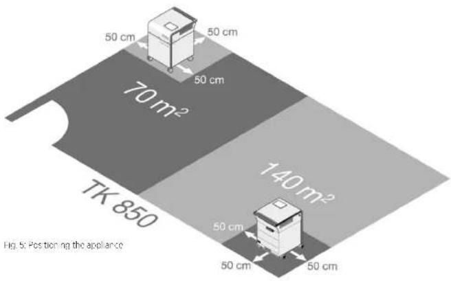
The mobile OurAir TK 850 is intended for use in rooms of up to 70 m ^2 with an air exchange rate of 5 times per hour. It is simply placed anywhere in the room. This also enables the effective use of a number of appliances in rooms that exceed a nominal size of 70 m ^2 .
flowchart
graph LR
    A["Input Image"] --> B["Image with wavy lines"]
    B --> C["Image with wavy lines"]
    C --> D["UV-C Filter"]
    D --> E["Output Image"]
    style A fill:#f9f,stroke:#333
    style E fill:#bbf,stroke:#333
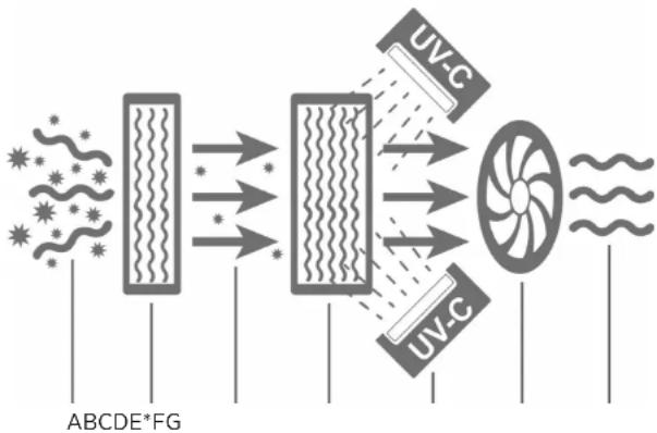
Fig. 2: Schematic illustration of the purification process
The schematic diagram illustrates the filtering process in your OurAir air purifier:
1. The fan (D) sucks in the contaminated ambient air (A) through the pre-filter element (B).
2. The pre-filter element (B) filters coarser, particulate impurities from the air. Optional is the additional use of an activated carbon filter element for removal of unpleasant smells and harmful gases.
3. The fan (D) directs the pre-filtered air (C) past the UV-C lamps (E*) to the inlet side of the HEPA filter (F), which filters all aerosol-borne substances from the air including pathogens such as bacteria and viruses to at least 99.995%.
4. At regular time intervals, the UV-C lights (E ^A ) reliably inactivate the pathogens deposited on the HEPA filter (F).
5. After filtering, the purified air (G) flows out of the OurAir air purifier back into the room.
* Applies to models with integrated UV lamps
Technical data
4 TECHNICAL DATA
Feature
Specification
| Weight (net / including packaging) 60 kg / 70 kg | |
| Dimensions (height x width x depth) 770 mm x 510 mm x 630 mm | |
| Voltage 220 - 240 VAC, 50 / 60 Hz | |
| Power cord 18 m long C14, IEC with Euro moulded plug | |
| Current consumption Max. 18 A | |
| Power consumption (operating) Max. 270 W | |
| Power consumption (UV-C light bulbs)* 2x 20W | |
| Protection class IP54 for electrical components(IP40 for ICC C20 connector) | |
| Overvoltage category | II |
| Fuse 4 A (internal fuse)Operation only permitted in circuits with residualcurrent operated circuit breaker (RCCB). | |
| Auto restart Yes. The appliance restarts if power is interruptedbriefly | |
| Display 7" LED touch screen | |
| Volumetric air flow10 levels from 0 - 950 m^3/h | Adjustable volume flows |
| Max. room size per appliance | 70 m^2 |
| Air circulation | 5 circulations per hour (for a 70 m^2 room) |
| Max. sound pressure level | ± 57 dB(A) |
| Pro. filter elementOptional: Activated charcoal filter (MERV 8 /ASI-RAC 52.2) | ISO cPM10 80% (as per EN 779 / ISO 16890) |
| IIEPA filter element(as per ISO 29463 & EN 1822, at 1000 m^3/h ) | IEPA II4 filter |
| Service life of the IIEPA filter element andpre-filter element: | approx. 2 years, depending on ambient conditions(Anzeige des Filter/zustands im LED-Display) |
| Ambient temperature / humidity | 0 - 40 °C / < 80 % % relative humidity |
| UV-C light bulbs* Wavelength / 254 mm / 7800 cdLuminous intensity | |
| Max. installation altitude of the unit aboveseal level | 2000 m |
| Scope of delivery | 1x OurAir SQ 2500 indoor air purifier |
| 1x IIEPA filter element (II4), pre-installed1x pre-filter element (ePMI 55%), pre-installed2x UV-C light bulbs (already installed)*1x 2 m power cord4x keys to open the housing1x Operating Manualmaintenance-free | 1x button cell CP2032 installed in the display, |
* Applies to models with integrated UV lamps
Technical data

NOTE
Check that the scope of delivery is complete and that there are no signs of damage. If the delivery comes with damaged parts, please inform your sales partner.

NOTE
For circuit diagrams and flow charts for the appliance, please contact the manufacturer.
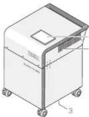
4.1 Appliance representation
The MANN-HIUMMEL OurAir TK 850 is a mobile IIEPA filter system for indoor use. The main features include touchscreen control, an ePM10 pre-filter element, a IIEPA-III4 filter element, UV-C light* bulbs, a fan, and a housing mounted or castors.
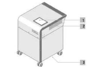
Front view
(1) Control element (LED touchscreen)
(2) Clean air outlet
(3) Air inlet
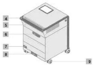
Rear view
(4) Transport handle
(5) Housing lid for access to HEPA filters
(6) Lid fastener with lock
(7) Integrated power socket and main switch
(8) Pre-filter element compartment
(9) Castors
text_image
Technical diagram of a 3D printer or scanner with labeled parts and directional arrowsFig. 3: TK 950 front view
text_image
4 5 6 7 8 9Fig. 4: TK 850 rear view
Installation
Installation
5 INSTALLATION
5.1 Transport
The OurAir TK 850 is equipped with four swivel castors and a handle for easy transport. Please follow these instructions before transporting the appliance:
WARNING!
Risk of injury when carrying the appliance due to its heavy weight!
In order to negotiate obstacles (e.g. stairs), the appliance should be lifted by at least two people
- Every person should wear appropriate foot protection!
- Switch off the appliance and unplug the power cord from the power socket at the back, using.
- Check that the Id of the appliance is locked and that the key can be removed from the lock
- The device should only be rolled on level and smooth surfaces by using the handle. After transport, the device should be upright and checked for possible damage.
- If you discover any damage to the device, please contact the customer service of your sales partner.
5.2 Positioning
text_image
50 cm 50 cm 50 cm 70 m² 140 m² TK 850 50 cm 50 cm 50 cm 50 cm Fig. 5: Positioning the appliance14 - EN EN - 15
Make sure that you meet the following conditions when setting up the appliance:
Only place and operate the appliance on flat, horizontal surfaces.
- Observe the load capacity of the floor. You will find the weight of the appliance on the type label.
- Do not operate the appliance in the bathroom or in rooms with high humidity.
- Once positioned at the place of operation, lock the castors to ensure that the device stands securely.
- Place the appliance as far as possible from the main entrance door of the room to be ventilated.
- Make sure there is a distance of 50 cm to walls and objects at the sides and back.

NOTE
In exceptional cases, distances of min. 20 cm are tolerable for short periods.
Make sure that the air inlet on the appliance is not blocked.
- If possible, distribute a number of appliances around a room so that the air is purified in all areas.
Commissioning
6 COMMISSIONING
6.1 Special safety instructions

CAUTION!
When connecting the appliance, observe the basic safety instructions in 2.1 on page 6.
Every Our Air TK 850 indoor air purifier has to pass a quality inspection before it leaves our factory. However, we have no control over any minor errors that may occur during shipping and handling.
We recommend that you check the following critical components before using your air purifier.
6.1.1 Electrical requirements

IG: ELECTRICAL VOLTAGE!
Using an unsuitable electrical supply for the appliance can lead to severe or fatal Injury!
- Only use the power cord supplied with the appliance!
- Ensure a suitable and safe power supply for the appliance!
- Operation is only permitted in circuits with residual current operated circuit-breaker (RCCB)!
- To avoid personal injury, fire hazards and/or damage to the electrical system and the appliance power cord, the appliance may only be connected to or disconnected from the power supply when the fan and the UV-C lamps* are switched off!
- The OurAir TK 850 requires a power supply of 220 - 240 V - at 50 / 60 Hz for correct operation.
- Only use extension cables with CE certification and the GS mark ("Geprüfte Sicherheit").
- Do not use multi-socket extenders for the power connection!
6.1.2 UV-C light bulbs\*

CAUTION!
Defective or incorrectly installed UV-C light bulbs can damage the appliance and the purification performance.
- Do not operate the appliance with UV-C light bulbs that have obvious signs of external damage.
- Before commissioning the appliance, make sure that the UV-C light bulbs are undamaged and correctly installed.
- Only touch the light bulbs by their end parts. Never touch the glass of the light bulb. Otherwise the effectiveness of the light bulbs will be impaired!
* Applies to models with integrated UV lamps
16 - EN EN - 17
Commissioning
6.1.3 Filter elements

CAUTION!
Defective or incorrectly installed filter elements impair the cleaning performance of the appliance! Before commissioning the appliance, make sure that the filter elements
are undamaged and correctly installed!
- Make sure that the pre-filter is correctly installed and undamaged.
- Note the correct flow direction, marked by a symbol on the side of the pre-filter.
- Make sure that the cover of the pre-filter housing is closed properly.
- Open the lid of the housing and check the HEPA filter for damage to the material or structure. Close the lid of the housing securely and remove the key.
6.2 Power supply
- Plug the supplied power cord into the integrated plug socket on the rear of the device (see Fig. 4, item 7 on page 13).
- Take hold of the plug to plug the power cord into the power socket (or a suitable extension cable).
- Switch on the appliance using the power switch next to the plug socket (see Fig. 4, item 7 on page 13).
- The appliance starts and shows the start screen on the LED display.
- Use the LED touch screen to operate the various functions of the appliance.
Operation Operation
7 OPERATION
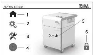
7.1 Home screen
After connecting the power supply, the appliance initializes itself and, after a brief wait, the LED display shows the home screen.
Menu items on the home screen
(1) Main menu
(2) Settings
(3) Service men.
(4) Device information
(4) Device information
(5) Display current volume flow
(5) Display current volume in (6) Status display protection
Tapping a menu item in the LED touch display takes you to the corresponding menu. The selected menu item then appears as a green symbol.
The home screen also shows the current volume flow of the appliance. The appliance is switched off at a volume flow of "0 m³/h".
text_image
16/10/20 01:13:34 MANN+ HUMMEL 1 2 3 i 5 0 m³/h 6Fig. 6: Home screen
7.2 Description of the controls
The LED display offers various controls of the following features.
Symbol
Meaning
| Feature switched off.Tap to switch the feature on. | |
| Feature switched on.Tap to switch the feature off. | |
| 0-Top and 400 m/s control to set the featureTo the dashed line. | 350 |
| Tap to open the screen with the advanced settings. | |
| Tap to return the settings. |
These elements are used to adjust the settings in the active menu items. Furthermore, there are some special control elements for particular settings, which are explained in the corresponding description.
18 - EN EN - 19
7.3 PIN code\*\*\*
7.3.1 PIN code screen protection ^4
By default the display is locked with a PIN code, which can be changed individually. Proceed as follows to unlock the display:
| Menu | Button | Action |
| Home screen | PIN code protection | The "PIN code protection" button takes you to be menu for programming the time. |
| IN code protection User no | 1 | Tap the "User No." input field. A numeric keypad opens.Enter the user number ".T". |
| Confirm inputEnter | Confirm the entry with the "Enter" key on the numeric keypad. | |
| Password | Tap the "Password" input field. A numeric keypad opens.Enter the PIN code.The default PIN code is !!!. | |
| Confirm inputEnter | Confirm the entry with the "Enter" key on the numeric keypad. | |
| LoginLogin | Alter entering the user number and PIN code, lap the "Login" button to unlock the display.The display returns to the home screen | |
| Home screen | PIN code protection | The open podlock symbol indicates that the PIN code protection for the display is unlocked.Tapping this button again activates the display's PIN code lock. |
** Applies to models with P/N code protection
Operation
Operation
7.3.2 Change PIN code ^4
You can change the preset PIN to a code of your choice. From the home screen, go to the "Settings" menu and then "Advanced Settings":
Menu
Button
Action
Settings Advanced settings On the display, lap the arrow to go to the "Advanced settings" view
Charge PW Tapping the "Charge PW" symbol opens the analogue for changing the P###de.

Old password: Top on the "Old password" input "eid. A numeric
keyoad opens.
Use it to enter the cu
The default P/N code is 1111.
Confirm input Confirm the entry with the "Enter" key on the
numeric keypad.

Entering an incorrect error
message. Confirm the message and re-enter the
correct current PIN code.
New password. If the entered PIN code was correct, tap the
"Confirr" bu.lar le

New password Tap or the upper "New Password" input field.
A numeric keypad of
Enter the new PIN code and confirm your entry
with the "Enter" key on the numeric keypad.
Tap or the lower "New Password" input field.
A numeric keypad opens
Enter the new PIN code and confirm your entry
with the "Enter" key on the numeric keypad.
The new PIN code can consist of up to 5 digits of
the numbers 0 - 3.
Note:
**Applies to models with PIN code protection
Menu
Button
Action
Password comparison. The PIN codes in the two input fields must match:
- If they match, a green tick appears next to the input fields. - If the entries do not match, a red cross appears next to the helus. In this case, enter the new PIN code again in both fields.
Confirm new password

This takes you back!
.
Confirm new password

This takes you back!
e Settings menu.
Access denied
in case of the wrong PIN code or an unauthorized
attempt to access the display, the following error
message appears

Password Protected
•
Access Denied!

Confirm this message and enter the correct
FIN code.
7.4 Starting the appliance
Menu
Button
Action
Settings System OFF/ON Start the appliance by tapping the
System OFF/ON" button.
- The button then appears in gr
- The appliance starts.
- Tap again to turn the appliance off.
- The button then appears in g
- The appliance starts.
- Tap again to turn the appliance off.
System OFF/ON" button.
Operation
7.5 Selecting the fan level
| Menu | Button | Action |
| Settings Air flow rate. Set the air flow rate in the apportionate menu by moving the slider to the desired position. | ||
| The following setpoint settings for air flow are assigned to the stages of the slider: | ||
| Controller Stage Air flow rate | ||
| 1 100 m3/h | ||
| 2 150 m3/h | ||
| 3 200 m3/h | ||
| 4 300 m3/h | ||
| 5 400 m3/h | ||
| 6 500 m3/h | ||
| 7 600 m3/h | ||
| 8 750 m3/h | ||
| 9 850 m3/h | ||
| 10 950 m3/h | ||
7.6 Manually switching the UV-C lamp on\*

NOTE
The recommendation is to use the UV-C lamps for no more than 30 minutes a day. Longer running times can shorten the service life of the HEPA filter.
| Menu | Button | Action |
| Settings UV in automatic mode, the UV-C lamps for disinfecting the HE-FA filter element are switched on and off at regular intervals each day.You as so have the option of starting the UV-C lamps manually with the "UV" button. The button then appears in green.Tap again to turn the lamps on.The UV-C irradiation is active for 30 minutes after switching on and then switches off automatically. | ||
* Applies to models with integrated UV lamps
22 - EN EN - 23
Operation
7.7 Automatic and manual mode
The appliance is suitable for manual and automatic operation (timer). In automatic mode, you can store the operating times for certain days of the week. As long as the automatic mode is active, the UV-C lamps are switched on and off automatically at regular intervals.

NOTE
For the best possible air purification, we recommend that you operate the appliance in automatic mode.
7.7.1 Manual mode
Proceed as follows to use the appliance in manual mode:
- Switch the appliance on (see section 7.4 on page 21).
- Set the fan level (see section 7.5 on page 22).
- Switch the UV-Clamps" on at regular intervals (see section 7.6 on page 22).
7.7.2 Automatic mode (timer)

CAUTION!
It is not possible to use an external timer to control the power supply of the appliance for scheduled air purification—this can damage the appliance! Always use the automatic mode provided by the appliance!

NOTE
In order for the time switch to work, please ensure that the date and time are set correctly in the appliance (see section 7.8.2 on page 25)
| Menu | Button | Action |
| Settings - Time Switch programming the timer. | The 'Time switch' button takes you to the menu for | |
| Switch function*Switch function * button.The button then appears green. | Activate the automatic mode by taoping the | |
| Weekdaydays on which the appliance should switch itselfon and off automatically. | In the list of weekdays, activate the buttons for the | |
| The timer is activated on days with a green button. | ||
| The timer is coactivated on days with a red button.Manual operation is still possible on these days. |
* Apolies to models with integrated UV lamps
Operation
| Menu | Button | Action |
| Switch-on time Touch the input field "Switch-on time" and a keyboard is displayed for entering the switch-onOn activated weekdays the appliance switches on automatic y at this time. | 700 | time |
| Switch-off time Touch the input field "Switch-off time" and a keyboard is displayed for entering the switch-offOn activated weekdays the appliance switches on automatic y at this time. | 1900 | time |
| Back The appliance immediately accepts your entries.The "Back" button takes your back to the "Sellings" | menu. | |
7.8 Advanced settings
7.8.1 Language
| Menu | Button | Action |
| Settings Advanced settings On the display, tap the arrow to go to the "Advanced settings" view. | ||
| Language be set as the language in the LED display. | Tap the country flag for the language you want to | |
| Back The appliance immediately accepts your entries.The "Back" button takes you back to the "Settings" | Monday | |
Operation
7.8.2 Date and time
| Menu | Button | Action |
| Settings Advanced settings. On the display, tap the arrow to go to the Advanced settings" view ▶ | ||
| Date/time Tap the clock iconThe dialogue for selling the date and time appears in the display | ||
| Service menu Current. DateM/16 / 03 / 21 | Tap the day, month, and year fields and use the | |
| Current time Select the current time HH MM SS1 / 11 / 56 | Tap the fields for the hour, minute, and second and | |
| Back The appliance immediately accepts your entries.The "Back" button takes you back to the "Advanced set tings" menu. | ||
| Back The "Back" button takes you back to the "Settings" | menu. | |
7.8.3 Display brightness
The display brightness can be adjusted for the ambient brightness.
| Menu | Button | Action |
| Settings: Advanced settings On the display, Iup the arrow to go to the Advanced settings" view | ||
| Backlight the desired position | 30 | Use the "Backlight" menu by moving the slider to 100 |
Operation
| Menu | Button | Action |
| Back The appliance immediately accepts your entries.The "Back" button takes up backTo the "Sellings" menu. | ||
7.9 Service menu
The service menu shows you the remaining service life of the filters and the operating hours of the appliance.
7.9.1 Show the remaining filter service life

Note
You are automatically informed when the filter elements should be changed. Under normal conditions of use, such as in offices, medical practices, schools and environments with regular room cleaning, it is recommended to replace both the prefilter and the HEPA filter at least every two years (if the filter replacement is not already indicated in the LED display beforehand). An earlier end of service life (due to improper use and increased contamination, for example) may be manifested by a louder operating noise or unusual odor development, among other things. In these cases, the prefilter must be replaced before the recommended service life has been reached.
| Menu | Button | Action |
| Service menu: FILL TER HEAL TH. The "FILL TER HEAL TH" field displays the filter service | ||
| Iliosed, if applicable, I'm formal on about the need | ||
| If the filter change: 10 of | ||
| So an indicator: the display shows the number of days while slowly changing to one green to red. | ||
7.9.2 Confirm filter change
After replacing the filter (see chapter 8 on page 28) you can reset the filter change indicator as follows.
| Menu | Button | Action |
| Service menu. In the 5 button for at least 2 seconds. The button changes to green and the message "G-4" is displayed. | Change filter |
Operation
7.9.3 Display operating hours
| Menu | Button | Action |
| Service menu Advanced settings in the service menu, tap the arrow to go to the "Operating hours" viewTitle showing via jux (in hours) are shown on the - Total operating hours- UV operating hours" | display: | |
| Back The "Back" button returns you. In the "Service menu" that o splays the titer health. | ||
7.9.4 Confirm light-bulb replacement\*
After replacing the UV-C light bulbs ^® (see chapter 9 on page 33) you can reset their operating hours counter as follows:
| Menu | Button | Action |
| Service menu Advanced settings in the service menu, tap the arrow to go to the "Operating hours" view. | ||
| Change UV light bulbs button for all levels 2 seconds. The button changes is displayed. | Confirm | In the operating-hours view, press the "Confirm" |
| Back The "Back" button returns you to the "Service menu" that e delays the filter with. | ||
7.10 Display device information
| Menu | Button | Action |
| Device information | The "Device information" menu shows you information about the appliance along with contact details for MANN-HUMMEL |
* Applies to models with integrated UV lamps
Filter replacement
Filter replacement
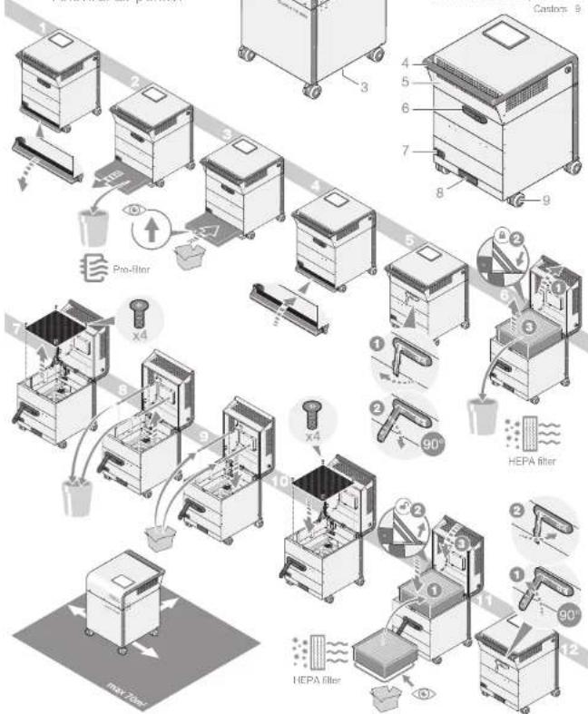
8 FILTER REPLACEMENT
8.1 Special safety instructions

NING: ELECTRICAL VOLTAGE!
Before you open the device, disconnect it from the power supply by unplugging the cord from the power outlet!

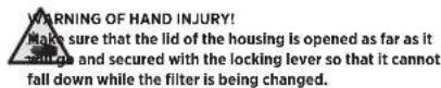
NING OF HAND INJURY!
Make sure that, when open, the lid of the housing is securely locked in place to avoid if it falls shut.

WARNING!
personal protective equipment (PPE)!
Personnel responsible for changing filters are strongly advised to wear appropriate personal protective equipment (PPE) and to follow safe work practices in accordance with legal and industrial safety regulations.
Use an FFP2 mask, disposable gloves, protective goggles and safety shoes when replacing the filter elements!


CAUTION!
The centre of gravity of the appliance is higher when the housing cover is open. Lock the wheels and ensure that the appliance stands securely.

CAUTION!
only spare parts approved by the manufacturer!

CAUTION!
Risk of damage to the replacement filter due to careless transport!
Avoid damaging the filter medium (filter paper) by touching the plastic frame of the other elements only!

CAUTION!
Risk of damage through the use of unauthorized cleaned air filters! We not reusable!
Do not try to clean and reuse the filters. Attempting to clean filters using methods such as compressed air can damage the filter and reduce filter efficiency.

NOTE
Dispose of the filters in accordance with statutory and local regulations. In general, used filters can be disposed of with the household waste.
Contact your local waste disposal authority for further instructions on proper disposal.
8.2 Filter replacement at a glance

TK850
Antiviral air purifier
natural_image
Technical line drawing of a portable kitchen appliance with wheels and a lid (no text or symbols)Control element LED touchscreen
Clean air outlet 2
Air inlet 3
+ Housing Id for access to HEPA filters. 5
Lid fastener with lock.
Integrated power socket and 7
main switch
Pre-After element compartment 8
Carlos B
flowchart
graph TD
    A["Raw Material Inspection"] --> B["Pre-filter"]
    B --> C["HePA filter"]
    C --> D["HePA filter with 90° angle indicator"]
    D --> E["HePA filter with 90° angle indicator"]
    E --> F["HePA filter with 90° angle indicator"]
    F --> G["HePA filter with 90° angle indicator"]
    G --> H["HePA filter with 90° angle indicator"]
    H --> I["HePA filter with 90° angle indicator"]
    I --> J["HePA filter with 90° angle indicator"]
    J --> K["HePA filter with 90° angle indicator"]
    K --> L["HePA filter with 90° angle indicator"]
    L --> M["HePA filter with 90° angle indicator"]
    M --> N["HePA filter with 90° angle indicator"]
    N --> O["HePA filter with 90° angle indicator"]
    O --> P["HePA filter with 90° angle indicator"]
    P --> Q["HePA filter with 90° angle indicator"]
    Q --> R["HePA filter with 90° angle indicator"]
    R --> S["HePA filter with 90° angle indicator"]
    S --> T["HePA filter with 90° angle indicator"]
    T --> U["HePA filter with 90° angle indicator"]
    U --> V["HePA filter with 90° angle indicator"]
    V --> W["HePA filter with 90° angle indicator"]
    W --> X["HePA filter with 90° angle indicator"]
    X --> Y["HePA filter with 90° angle indicator"]
    Y --> Z["HePA filter with 90° angle indicator"]
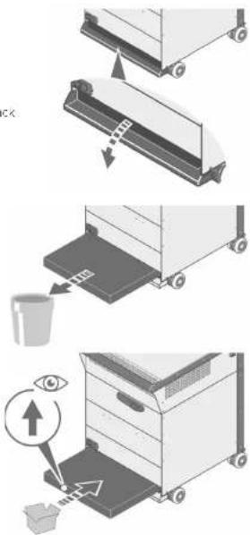
8.3 Replacing the pre-filter

Note
Under normal conditions of use, such as in offices, medical practices, schools and environments with regular room cleaning, it is recommended to replace both the prefilter and the HEPA filter at least every two years (if the filter replacement is not already indicated in the LED display beforehand). An earlier end of service life (due to improper use and increased contamination, for example) may be manifested by a louder operating noise or unusual odor development, among other things. In these cases, the prefilter must be replaced before the recommended service life has been reached. Operating the UV-C lamps' longer than the recommended 30 minutes per day can shorten the service life of the HEPA filter.
Proceed as follows to replace the pre-filter:
- Switch off the fan and the UV-C lamps*.
- Pull on the plug to remove the power cord from the socket on the appliance.
- Open the cover of the pre-filter compartment on the back of the device by pulling down on the recessed grip in a clockwise direction.
- Pull out the pre-filter horizontally.
For filter disposal, please observe the special safety instructions on page 28. - Push the new pre-filter horizontally into the pre-filter compartment as far as it will go until it is fully inserted.

CAUTION!
the arrow on the side of the
filter points in the direction of air flow.
arrow must point upwards when
inserting the filter element.
text_image
Diagram illustrating a three-step cleaning or packaging process with labeled steps and an eye icon indicating inspection.* Applies to models with integrated UV lamps
Filter replacementFilter r
- Use the handle to close the cover.
The lid stays in place as soon as it is closed.
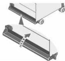
natural_image
Diagram showing two mechanical components with arrows indicating motion or assembly (no text or symbols)8.4 Replacing the HEPA filter

WARNING!
HEPA filter element weighs up to 10 kg and has sharp edges. We wear safety shoes to protect against leg and foot injuries should the filter ment be dropped.


CAUTION!
centre of gravity of the appliance is higher when the housing cover is open. The wheels and ensure that the appliance stands securely.
Proceed as follows to replace the HEPA filter:
- Switch off the fan and the UV-C lamps (see the sections 7.3 and 7.6 from page 19).
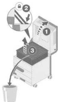
2 Use the plug to remove the power cord from the socket on the back of the appliance. - Use the supplied key to unlock the lid fastener on the rear of the housing.
- Now unlock the lid by pulling out the locking lever at its the right-hand end, and turn it 90° downwards.

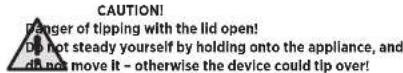
CAUTION!
ger of tipping when opening the housing lid! the castors before you open the housing lid!
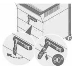
natural_image
Illustration of a mechanical device with two circular insets showing angles (90°) and directional arrows, no readable text or symbols present.* Applies to models with integrated UV lamps
Filter replacement
- Open the lid of the housing using the handle until it clicks vertically into place.
- Grasp the HEPA filter on the side of the frame and pull it up and out of the housing. To protect against injury, avoid direct contact with the filtration surface.
For filter disposal, please observe the special safety instructions on page 28.
- Align the new HEPA filter so that its rubber seal faces down towards the grille that separates the filter compartment from the fan compartment.
B. Insert the new HEPA filter into the housing so that its rubber seal faces downwards. Lightly press the filter element down so that it is firmly seated in the housing.
-
Slowly close the Id with one hand while at the same time using the other hand to push the locking lever forwards to release the locking mechanism. Then grab the transport handle with both hands and carefully lower the Id until it is completely closed.
-
As soon as the lid is closed, fasten it with the locking lever by turning it 90° anti-clockwise and then pressing it into the housing.
Removing the key ensures that the lid remains locked and cannot be opened by unauthorized persons.
text_image
Diagram illustrating a mechanical device with numbered components and directional arrows, likely illustrating a process or assembly.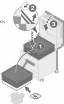
text_image
Diagram illustrating a robotic arm with labeled parts and directional arrows, including eye detection and mechanical components.
Light bulb replacement
9 LIGHT BULB REPLACEMENT\*
9.1 Special safety instructions
text_image
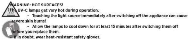
WARNING: HOT SURFACES! (The UV-C lamps get very hot during operation. - Touching the light source immediately after switching off the appliance can cause severe skin burns! - Allow the lamps to cool down for at least 15 minutes after switching them off before you replace them. - If in doubt, wear heat-resistant safety gloves.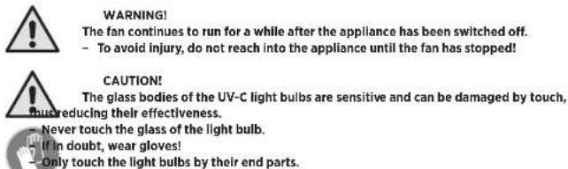
text_image
WARNING! The fan continues to run for a while after the appliance has been switched off. - To avoid injury, do not reach into the appliance until the fan has stopped! CAUTION! The glass bodies of the UV-C light bulbs are sensitive and can be damaged by touch, bureducing their effectiveness. - Never touch the glass of the light bulb. If in doubt, wear gloves! - Only touch the light bulbs by their end parts.
text_image
CAUTION! Do not dispose of used UV-C light bulbs in the household waste. - Contact your local waste disposal authority for instructions on proper disposal. - Further information on disposal can be found in chapter 14 on page 39 of these operating Instructions.
text_image
NOTE Due to the production process, new light bulbs can develop an unusual smell due to the high-energy radiation. This odour usually disappears within the first 20 - 50 hours of operation.* Applies to models with integrated UV lamps
Light bulb replacement
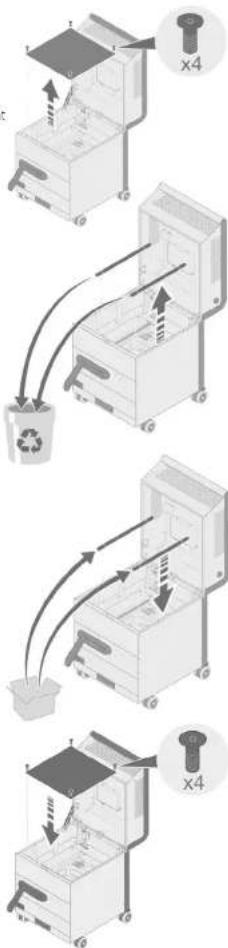
9.2 Replacing the light bulbs
Proceed as follows to replace a UV-C light bulb:
- Remove the HEPA filter element. To do this, to low the steos in the section 8.4 on page 31.
- Undo the 4 screws of the grille separating the filter compartment from the fan compartment, and pull the grille up and out of the housing.
- Release each light bulb from its holder.
- Then carefully pull each light bulb out of its socket.
text_image
CAUTION! No not dispose of used UV-C light bulbs in the household waste. Contact your local waste disposal authority for instructions on proper disposal. Further information on disposal can be found in chapter 14 on page 39 of these operating instructions.- Insert the each new UV-C light bulb into the socket provided for it and snap the upper end into its holder.
- Insert the grille into the filter compartment from above and secure it with the screws.
- Insert the HEPA filter, to do this, follow the steps in the section 8.4 on page 51.
- Reset the operating-hours counter for the light bulbs in the LED display (see section 7.9.4 on page 27).
* Applies to models with integrated UV lamps
flowchart
graph TD
    A["Receipt"] --> B["Recycle Bin"]
    B --> C["Paper feeding into Machine"]
    C --> D["Recycle Bin with Paper"]
    D --> E["Recycle Bin with Paper"]
    E --> F["Recycle Bin with Paper"]
    F --> G["Recycle Bin with Paper"]
34 - EN EN - 35
Care
10 CARE
10.1 Special safety instructions

NING: ELECTRICAL VOLTAGE! housing of the appliance is not waterproof!
Keep electrical components dry, as contact with liquids can lead to life-threatening and damage to components.
10.2 Regular maintenance
- Clean the LED display regularly with a microfibre cloth.
- As required, clean the appliance with a lamp cloth, a water-based cleaner, or a
germicidal or antimicrobial detergent. - Do not use harsh chemicals, so vents, or detergents to clean the appliance.
- Periodically remove dust and other debris from the outside of the air inlet and outlet
slots to ensure proper air intake and exhaust. - Clean the castors regularly so that the appliance can be moved safely and without jamming the castors.
11 SERVICE AND MAINTENANCE
11.1 Special safety instructions

WARNING! Cleaning and maintenance work may only be carried out by persons who are familiar with the operating instructions and in compliance with the following instructions!

WARNING! Of fire, electric shock, or injury! Before cleaning, servicing or maintenance work, always switch off the fan and the lamps+ and disconnect the power cord from the power outlet! For operate the appliance without filter elements! Not bypass any safety mechanisms!
* Applies to models with integrated UV lamps
Service and maintenance

WARNING!
r personal protective equipment (PPE)!
Use an FFP2 mask, disposable gloves, protective goggles and safety shoes when the filter elements!


ING OF HAND INJURY!
Use an arresting mechanism for open doors and flaps when conducting maintenance
11.2 Maintenance plan
The appliance is designed for minimal maintenance and long operating times. Nevertheless, please adhere to the following maintenance intervals in order for the appliance to operate most effectively.
Activity Maintenance and servicing Intervals
| Before use As required | At least every two | years | |
| Clean the exterior | X | ||
| Check for damage | X | ||
| Text run | X | ||
| Replace the HEPA filter | X | ||
| Replace the ore filter | X | X |
11.3 Re-orderable accessories
To order accessories, please contact the customer service of your sales partner.
| Name | MANN+HUMMEL item number |
| Pre-filter (ePM10 80%) | 800221039527 |
| HEPA filter (HI4) | 800536066231 |
| UV-C light bulbs | Please contact M+H Service |
| Base for UV-C light bulbs | Please contact M+H Service |
| Fan | Please contact M+H Service. |
36 - EN EN - 37
Storage

NOTE
Use replacement parts from the manufacturer only, including the recommended replacement filters.
The use of spare parts and filters not approved by MANN+HUMMEL will void all warranties and performance claims.
12 STORAGE
12.1 Storing filter elements

CAUTION!
- Protect stored filter elements against UV radiation, dust, moisture and damage. - Store the filter elements out of the reach of insects and rodents.
- If possible, keep at least one spare element in stock for each filter element used. MANN+HUMMEL guarantees the function of properly stored filter elements for up to 4 years after purchase.
12.2 Storage
Please observe the following instructions when the appliance is not in use:
- Store the device in an upright position and protect it from direct sunlight.
- Use a suitable cover to protect the appliance from dust.
- Protect the device from frost and extreme heat.
After longer periods of storage, please check the condition of the power cord, the filter elements and the UV-C light bulbs. If you require spare parts for defective or expired components, please contact the customer support of your sales partner.
- Have the appliance checked annually by a qualified electrician to ensure that it is in good working order.

CAUTION!
Use only original MANN+HUMMEL spare parts to replace defective or used components! The use of spare parts and filters not approved by MANN+HUMMEL will warranties and performance claims.
* Applies to models with integrated UV lamps
Troubleshooting
13 TROUBLESHOOTING
Should you ever have a problem with the product, please try to correct it using the measures described below. If the air purifier still does not work properly after this, please contact our customer service.

CAUTION!
Use only original MANN+HUMMEL spare parts to replace defective or used components! The use of spare parts and filters not approved by MANN+HUMMEL will warranties and performance claims.
Fault / error Cause Solution
| The air purifier does not No power supply. Check that the appliance is connected in a work - power outlet. | ||
| of the appliance. | Air purifier not switched on | Check the position of the switch on the back |
| I did not closed and locked | Close and lock the lin | |
| The volumetric airflow shown on the display is "O m2/h" | Increase the airflow. | |
| Date and time set incorrectly for automatic mode | Set the correct date and time. | |
| Little or no air is coming out of the clean-air outlet. | Air purifier not switched on | Turn on the air purfer |
| Air inlet or outlet slots blocked objects and contaminants from the air inlet, and outlet slots. | Remove any blockages due to foreign | |
| The LED display shows the filter status "Replace" or "Alert". | Replace both filters. | |
| A strange smell is coming from the clean-air outlet. | Filter heavily contaminated or at the end of its service life. | Replace both filters. |
| by the UV C lumps* not a fault. The smell will disappear over. | Disinfection of ,the HEPA filler element light bulbs* can cause a sight colour. This is time. | In the 1st few weeks of use, new UV-C |
| The device makes unnatural noises. | Foreign objects or other loose objects are on or in the air-inlet and air-outlet slots | Remove these objects. |
| Fault cannot be remeched by yourself sales partners. | Please contact the customer service of your | |
Applies to models with integrated UV lamps
38 - EN EN - 39
Disposal
14 DISPOSAL
Contact your local waste disposal authority for further instructions on proper disposal of appliance components.
14.1 Environmental protection
Correct disposal of this appliance (waste electrical and electronic equipment) and the battery it contains.
The OurAir TK 850 air purifier is an electrical/electronic device. At the end of its life, or if the device otherwise becomes waste, you are required by law to dispose of it separately from unsorted municipal waste. You can return it either to a municipal collect on point for waste electrical and electronic equipment, or to a retailer. Disposal of the device in the res dual waste garbage is prohibited. This is expressed by the symbol with the crossed-out trash can. The display of the device contains a CR2032 button col., This can remain in the device during disposal. You can return it free of charge at the product's point of sale. You can also make use of collection points for electrical and electronic equipment in your area. Please contact your city or local authority to find out about the addresses of the collection points.
14.2 Filters
Dispose of pre-filters and HEPA filters in accordance with statutory and local regulations. You can generally dispose of used filters in an airtight plastic bag in the household waste.
14.3 UV-C light bulbs\*

CAUTION!
dispose of used UV-C light bulbs in the household waste. - Contact your local waste disposal authority for instructions on proper disposal.

* Apolies to models with integrated UV lamps
Declaration of Conformity
15 DECLARATION OF CONFORMITY
MANN-HUMYEL Vokes Air GmbH & Co. O-IG hereby declares that this equipment is in conformity with the essential requirements and other relevant provisions of Directives 2006/42/EC, 2011/65/EU and 2014/30/EU. The complete EU Declaration of Conformity can be viewed at: Link

JMMEL Vokes Air GmbH & Co. OHG er Weg 14-16, 45549 Sprockhövel, Germany 141 98-2601

MANN+HUMMEL
OurAir TK 850
15 DÉCLARATION DE CONFORMITÉ
PORTER AU MANUEL D'EMPLOI
text_image
MANN+HUMMEL Vickers Air GmbH & Co. ONG Erfelshelke's Way 14-16 D-35645 Spokrakkel Indoor Air Purifier OurAir TK 550 6 5 4 6 7 8 9 10 Designed and Engineered in Germany Made in ChinaFigure 1: Plaque signalélique
3 DESCRIPTION FONCTIONNELLE
text_image
Technical diagram of a portable air conditioner unit with labeled parts 1 and 2Installation Installation
5 INSTALLATION
Luis cie to solate of
natural_image
Mechanical assembly diagram showing two views of a vehicle with a lever and guide mechanism (no text or symbols)
natural_image
Illustration of a trash bin with a bucket, no text or symbols present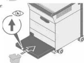
text_image
Diagram illustrating eye imaging process with labeled components and directional arrowsnatural_image
Diagram showing two mechanical components with arrows indicating motion or assembly (no text or symbols)natural_image
Diagram showing two views of a wall-mounted pipe installation with angle annotation (90°), no text or symbols present.
ATTENTION!
text_image
Diagram illustrating a mechanical device with numbered components and directional arrows, likely illustrating a process or assembly.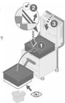
text_image
Diagram illustrating a robotic device with labeled components and an eye symbol, showing process steps and directional arrows.
text_image
Diagram illustrating a recycling process with labeled components and directional arrows, including a magnified view of the 'x4' component.
text_image
Diagram illustrating a mechanical device with labeled components and directional arrows indicating motion or force.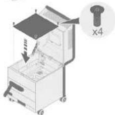
text_image
Diagram of a mechanical device with labeled parts and a magnified inset showing a bolt and part number X410 ENTRETIEN
15 DÉCLARATION DE CONFORMITÉ
text_image
MANN+ HUMMEL Vickers Air GmbH & Co. OHG Einzetholder Wtg 14-15 D-23649 Sprachhol Indoor Air Purifier- OurAir TK 850 Serial number: Part number: Volume: Frequency: Power: Current: Weight Manufacturing dade: YYYY Designed are Engineered in Germany Made in China MANN+ HUMMEL 5 6 7 8 9 10Figura 1: Targhetta
m = 311
are
I tastiorino
n. n. n.
text_image
Diagram illustrating a three-step industrial process for handling a machine, with arrows indicating steps and an eye icon highlighting the process.natural_image
Diagram showing two mechanical components with arrows indicating motion or assembly (no text or symbols)natural_image
Illustration of a mechanical device with two circular insets showing angle measurement (90°) and directional arrows, no readable text or symbols present.
ATTENZIONE!
text_image
Diagram illustrating a process with numbered steps and directional arrows, likely for a machine operation or inspection.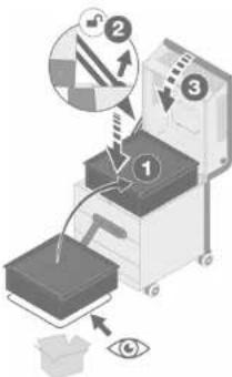
text_image
Diagram illustrating a mechanical or optical setup with labeled components and directional arrows, including eye and magnified views.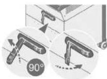
Leadership in Filtration
MANN+ HUMMEL
Índice
Índice
Índice
1 INTRODUCCIÓN 4
1.1 Fabricante y editor 4
1.2 Simbologia
1.2.1 Enumeraciones
1.2.2 Acciones
text_image
MANN+HUMMEL Vokes Air GmbH & Co. CHG Eubuchholter/Wig 14-15 D-45646 Sprochholter Indoor Air Purifier- OurAir TK 850 Solid chamber: Part chamber: Frequency: Impurity: Power: Current: Weight: Manufacturing unit: YYYY Designed and Engineered in Germany Mann+ HUMMEL 6 5 7 8 9 10 Made in Chinatext_image
Technical diagram of a portable air conditioner unit with labeled parts 1, 2, and 3natural_image
Diagram showing two mechanical components with arrows indicating motion or assembly (no text or symbols)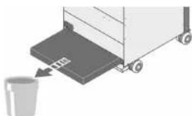
natural_image
Illustration of a trash bin with a bucket, no text or symbols present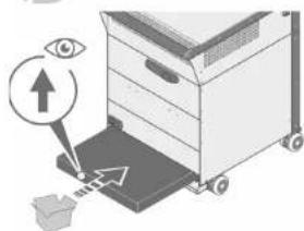
text_image
Diagram illustrating eye detection mechanism with labeled eye icon and directional arrows on a devicenatural_image
Diagram showing two mechanical components with arrows indicating motion or assembly (no text or symbols)natural_image
Illustration of a mechanical device with two views showing angle measurement (90°), no text or symbols present.
ATENCIÓN
text_image
Diagram illustrating a printer operation with numbered steps and directional arrows, likely for printing or sorting.
text_image
Diagram illustrating a mechanical or optical setup with labeled components and directional arrows, including eye and magnified views.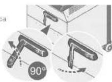
text_image
Diagram illustrating a recycling process with labeled components and arrows indicating movement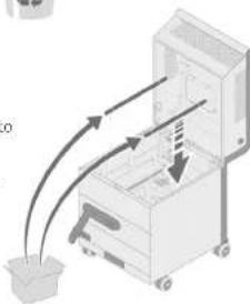
natural_image
Illustration of a mechanical device with arrows indicating motion or force direction (no text or symbols)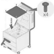
text_image
Diagram of a mechanical device with labeled parts and a magnified inset showing part X410 LIMPIEZA
text_image
MANN+ HUMMEL Vickers Air GmbH & Co. OHG Einzetholder Wtg 14-15 D-23649 Sprachhol Indoor Air Purifier- OurAir TK 850 Serial number: Part number: Volume: Frequency: Power: Current: Weight Manufacturing dtd. YYYY Made in China Designed and Engineered in Germanytext_image
Technical diagram of a portable air conditioner unit with labeled parts 1, 2, and 3Ayarlar Sistem KAFALI/ACIK Start the device by pressing the button
text_image
in cckin.natural_image
Diagram showing two mechanical components with a directional arrow indicating movement or force (no text or symbols present)natural_image
Illustration of a cabinet with hanging fixtures and a 90-degree angle indicator (no text or symbols present)
DİKKAT!
text_image
Diagram illustrating a printer operation with labeled steps and directional arrows, including a magnified view of the printer's internal structure.
text_image
Diagram illustrating a mechanical or optical setup with labeled components and directional arrows, including eye and gear symbols.
9 LAMBA DEĞİŞİMİ\*
text_image
Diagram illustrating a recycling process with labeled components and arrows indicating movement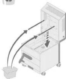
natural_image
Illustration of a mechanical device with arrows indicating motion or force, no text or symbols present