EKLN140A1 - Air Conditioning DAIKIN - Free user manual and instructions
Find the device manual for free EKLN140A1 DAIKIN in PDF.


User questions about EKLN140A1 DAIKIN
0 question about this device. Answer the ones you know or ask your own.
Ask a new question about this device
Download the instructions for your Air Conditioning in PDF format for free! Find your manual EKLN140A1 - DAIKIN and take your electronic device back in hand. On this page are published all the documents necessary for the use of your device. EKLN140A1 by DAIKIN.
USER MANUAL EKLN140A1 DAIKIN
natural_image
Exterior view of a DAIKIN industrial heat exchanger unit (no signage or text beyond branding)EKLN140A1
Installation manual Low sound enclosure
3 About the unit and options 3
3.1 Possible combinations.... 3
3.2 Possible options .... 3
4 Unit installation 3
4.1 Preparing the installation site 4
4.2 About fitting the enclosure.... 4
4.2.1 About installing the base frame.... 4
4.2.2 About installing the support frame 4
4.2.3 About installing the outdoor unit....5
4.3 Wiring 6
4.3.1 To prepare the wiring 6
4.3.2 To position the wiring 6
4.4 About fixing the outdoor unit....7
4.4.1 To fix the outdoor unit 7
4.5 About installing the slats frame 7
4.5.1 To install the slats frame 7
4.6 About installing the slats....7
4.6.1 To install the lower slats....7
4.6.2 To install the intermediate slats 8
4.6.3 To install the upper slats 8
4.7 About installing the panels and sealing strips 9
4.7.1 To install the top panel....9
4.7.2 To install the side panels and sealing strips ..... 9
5 Configuration 9
6 Maintenance 10
1 About the documentation
1.1 About this document
Target audience
Authorised installers
Documentation set
This document is part of a documentation set. The complete set consists of:
- Option installation manual:
- Installation instructions
- Format: Paper (in the box of the option)
Latest revisions of the supplied documentation may be available on the regional Daikin website or via your dealer.
The original documentation is written in English. All other languages are translations.
Technical engineering data
- A subset of the latest technical data is available on the regional Daikin website (publicly accessible).
- The full set of latest technical data is available on the Daikin Business Portal (authentication required).
2 About the box

NOTICE
Before installation, check the packaging and parts for damage. Make sure that the shipment is complete.
2.1 Parts
The box contains the following parts:
- Base frame profile, front (1×)
- Base frame profile, rear (1×)
- Base frame profile, left (1×)
- Base frame profile, right (1×)
- Support beam, front (1×)
- Support beam, rear (1×)
- Support partition, upper (1×)
- Support partition, lower (1×)
- Support frame sealing pad (1×)
- Vertical support, left (2×)
- Vertical support, right (2×)
- Lower slat (2×)
- Intermediate slat (8×)
- Upper slat (2×)
- Top panel (1×)
- Side panel, left (1×)
- Side panel, right (1×)
- Sealing strips
2.2 Accessories
The box contains the following accessories:
| Accessories(a) | Illustration | Description |
| A |  | Torx screw M5×20 |
| B |  | Washer M5 nylon DIN 125-1A |
| C Sealing tape 20 mm |  | |
| D |  | Nylon plug 8×40 |
| E | 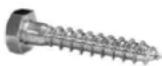 | Lag screw 6×50 |
| Accessories(a) | Illustration Description | |
| F | 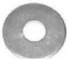 | Sheet metal washer M6×20 |
| G | 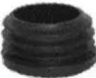 | Round spacer cap |
| H Spring washer M8 | 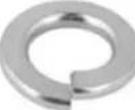 | |
| I | 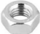 | Nut M8 |
| J | 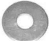 | Sheet metal washer M8×30 |
| K | 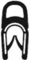 | Rounded finishing profile, small |
| L | 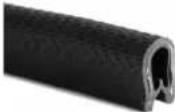 | U-shaped finishing profile |
| M Guide pin ∅8×25 M5 | 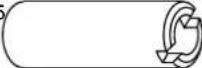 | |
| N | 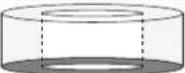 | Spacer bush 15×2.5 |
| O | 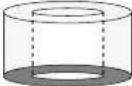 | Spacer bush 12×7 |
| P | 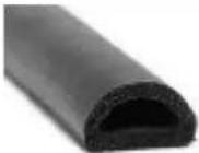 | D-rubber sponge, self-adhesive |
| Q | 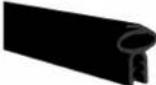 | Rounded finishing profile, big (1 m) |
| R | 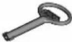 | Key |
| Accessories(a) | Illustration Description | |
| S |  | Base frame corner bracket |
| T |  | Base frame sealing pad |
| U | 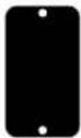 | Base frame sealing pad |
| V | 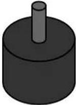 | Vibration damper |
(a) This manual refers to each accessory with a specific letter from A to V.
3 About the unit and options
3.1 Possible combinations
See the data book of the outdoor unit to check if the low sound enclosure is compatible with the outdoor unit.
3.2 Possible options
Drain pan and heater tape
To evacuate drain water, use:
- Drain pan (EKLN140-DP)
To keep the drain holes free in cold climates, also use:
- Heater tape (EKLN140-DPHT)
4 Unit installation

WARNING
Installation shall be done by an installer, the choice of materials and installation shall comply with the applicable legislation. In Europe, EN378 is the applicable standard.

WARNING
Installation MUST be carried out by an authorised installer. 2 people are required to install the low sound enclosure.

WARNING
The parts may have sharp edges. Wear cut-resistant work gloves during installation.
4.1 Preparing the installation site

WARNING
Make sure installation, servicing, maintenance and repair comply with instructions from Daikin and with applicable legislation and are executed ONLY by authorised persons.
Requirements relating to the installation
Ensure a horizontal, level and stable base (a paved base or a wooden frame). There MUST be a minimum clearance of 1 meter on all sides of the frame.
See the installer reference guide of the outdoor unit for additional installation site requirements of the outdoor unit in cold climates.
Tools
The low sound enclosure can be installed using following tools:
- Cut-resistant work gloves
- Wire cutters
- Utility knife
- Measuring tape
- Try square
- Neutral cleaning agent
- Screwdriver, Torx TX25
- (Pipe) wrench size 10
- Key size 13
- Drill with 8 mm masonry bit (if the foundation is made of concrete)
4.2 About fitting the enclosure
4.2.1 About installing the base frame
text_image
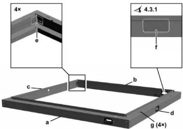
4x e 4.3.1 f c b a d g (4x)a Base frame profile, front
b Base frame profile, rear
c Base frame profile, left
d Base frame profile, right
e Base frame corner brackets (accessory S)
f Base frame sealing pad (accessory U)
9 Fixation holes
To install the base frame
The base frame comprises 4 straight pieces (a\~d) and 4 corners (e). The 4 straight pieces have recesses at the ends to allow them to slot together.
1 Tilt the corner brackets (accessory S) into the corners.
2 Fix the corners with M5 Torx screws (accessory A) and washers (accessory B).

INFORMATION
Tighten them hand-tight (tightening torque <5N·m).
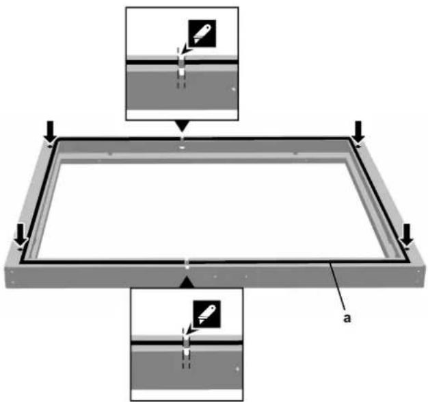
3 Affix 1 strip of sealing tape (accessory C) to the bottom side of the base frame in the centre of the profile.
text_image
Technical diagram showing a rectangular plate with two inset views and labeled component 'a', likely illustrating a mechanical or structural assembly.a Sealing tape (accessory C)
4 Interrupt the rubber at the drain holes (2×) and fixation holes (4×).
5 Align the base frame in a 90° angle – a large try square would be most appropriate for this.

INFORMATION
The corners MUST be exactly 90°.
6 Fix the base frame to the floor with the lag screws (accessory E) and the sheet metal washers (accessory F).
7 (Optional) If working with a stony base, use the nylon plugs (accessory D).
8 Fit 4 round plastic spacer caps (accessory G) to the base frame and press them into the fixation holes at the top, over which the panels will be fitted later.
4.2.2 About installing the support frame
text_image
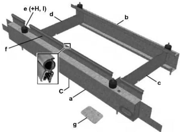
e (+H, l) d b f c C a ga Support beam, front
b Support beam, rear
c Support partition, upper
d Support partition, lower
e Vibration dampers (accessory V)
f Rounded rubber (accessory Q)
g Base frame sealing pad (accessory T)
C, H, I, L Accessories
To install the support frame
1 Position the front support beam (a) and rear support beam (b) parallel to one another with the open sections facing one another.
2 Slide the upper support partition (c) and lower support partition (d) between the 2 support beams.
3 Check that all holes in the support bars and partitions are aligned with one another.
4 Connect the vibration dampers (accessory V) to the support beams and partitions using the M8 spring washers (accessory H) and M8 nuts (accessory I).
5 Connect the support beams and partitions to one another using the M5 Torx screws (accessory A) and washers (accessory B).

INFORMATION
Tighten them hand-tight (tightening torque <5N·m).
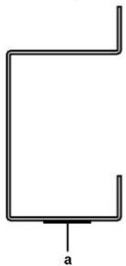
6 Affix 1 strip of sealing tape (accessory C) to both support beams in the centre of the front support beam profile (a) and rear support beam profile (b).
natural_image
Pure geometric line drawing of a C-shaped structure with a base labeled 'a' (no text or symbols beyond label)a Sealing tape (accessory C)
7 (Optional) If you use the support frame as the base of the drain pan: cut the U-shaped finishing rubber (accessory L) into 4 equal parts of 3 cm long and place them on the top ends of both intermediate support partitions on the upper part.

natural_image
3D mechanical assembly diagram showing a frame with mounting holes and mounting points (no text or symbols)8 Fit the front of the foremost support beam with rounded rubber (accessory Q).
9 Cut the correct lengths and ensure that the rubber is interrupted at the notches.
10 Click the support frame into the base frame using the grooves.
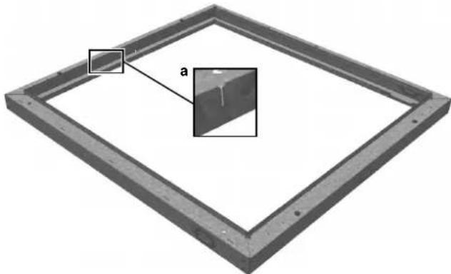
natural_image
Diagram of a rectangular frame with a small inset showing a cross-section labeled 'a', no text or symbols present.a Location of groove in base frame
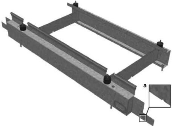
natural_image
3D mechanical assembly diagram showing a frame structure with mounting holes and a small inset view labeled 'a' (no text or symbols present)a Location of groove in support frame
11 Fix the foremost support beam to the floor using the lag screws (accessory E), sheet metal washers (accessory F), and plugs (accessory D) if working with a stony base.
Result:
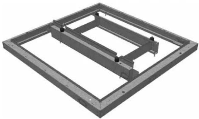
natural_image
3D rendering of a rectangular metal frame structure with mounting holes and internal supports (no text or symbols)4.2.3 About installing the outdoor unit

INFORMATION
For details about installation of the outdoor unit, see the manual of the outdoor unit.

CAUTION
When installing the low sound enclosure on an existing outdoor unit, the wiring and refrigerant piping MUST go through 1 of the 3 premounted openings in the base frame of the low sound enclosure.
ALWAYS follow the instructions in the installation manual and service manual of the outdoor unit for the related procedures to uninstall and reinstall the outdoor unit.
To install the outdoor unit
1 If necessary, fix the rearmost support beam using lag screws (accessory E) and washers (accessory F).
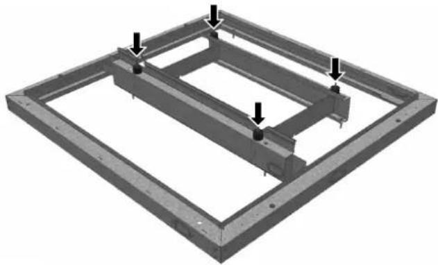
natural_image
3D diagram of a structural frame with mounting holes and internal supports (no text or symbols)2 (Optional) If working with a stony base, use the plugs (accessory D).
3 Place the outdoor unit on the vibration dampers and connect them consecutively using the sheet metal washer (accessory J), spring washer (accessory H), and nut (accessory I).
4.3 Wiring
4.3.1 To prepare the wiring
1 Choose the desired opening in the base frame for the pipes and electrical wiring.
2 Seal the other openings using the provided base frame sealing pads (accessory T and U).

INFORMATION
If the cables enter from the bottom, all openings can be sealed.
3 Fix with M5 Torx screws (accessory A) and washers (accessory B).

INFORMATION
Tighten them hand-tight (tightening torque <5N·m).
4.3.2 To position the wiring
1 Insert the small rounded finishing rubber (accessory K) into the opening through which the cables are passed to ensure the perfect seal between the opening and pipes and cables.
2 Cut the rounded finishing rubber (accessory K) to the correct size with a utility knife and place it on the inside of the opening.
3 Place a strip of U-shaped finishing rubber (accessory L) on the inside of the base frame to prevent damage to the pipes and cables.
4 Pull the pipes and electrical cables through.
5 Guide the pipes and electrical cables through the floor (base) entry point of the outdoor unit to prevent kinks in the pipes.
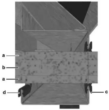
text_image
a b a d ca Insulation
b Refrigerant piping
c Small rounded finishing profile (accessory K)
d U-shaped finishing profile (accessory L)
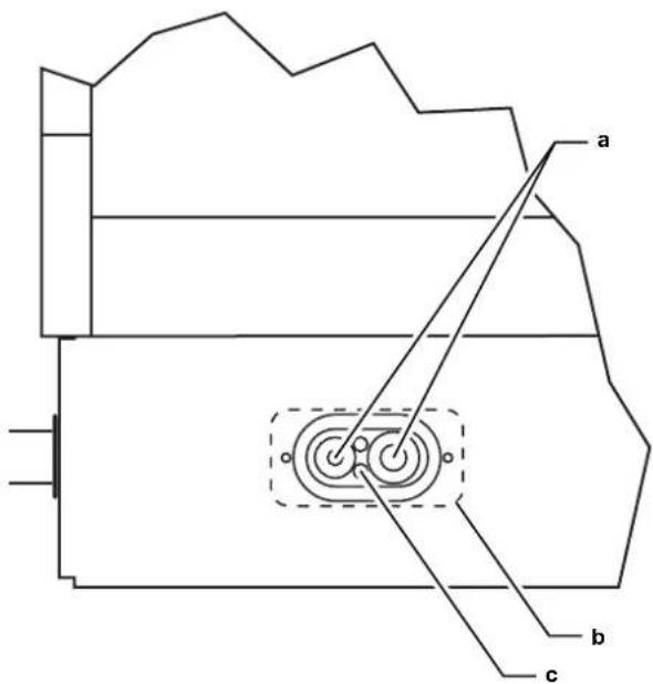
text_image
a b ca Refrigerant piping
b Cover plate positioned from inside. Placed in 3 positions (see top view). Pipes are sealed with rubber.
c Electrical cables
4.4 About fixing the outdoor unit
4.4.1 To fix the outdoor unit
1 Fix the outdoor unit with the M8 sheet metal washer (accessory J), M8 spring washer (accessory H), and M8 nut (accessory I).
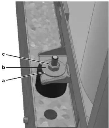
text_image
a b ca Sheet metal washer M8 (accessory J)
b Spring washer M8 (accessory H)
c Nut M8 (accessory I)
2 Connect the pipes and cables from the outdoor unit according to the installation manual for the outdoor unit.
4.5 About installing the slats frame
4.5.1 To install the slats frame
1 Position the vertical supports left (a) and right (b) on the base frame.
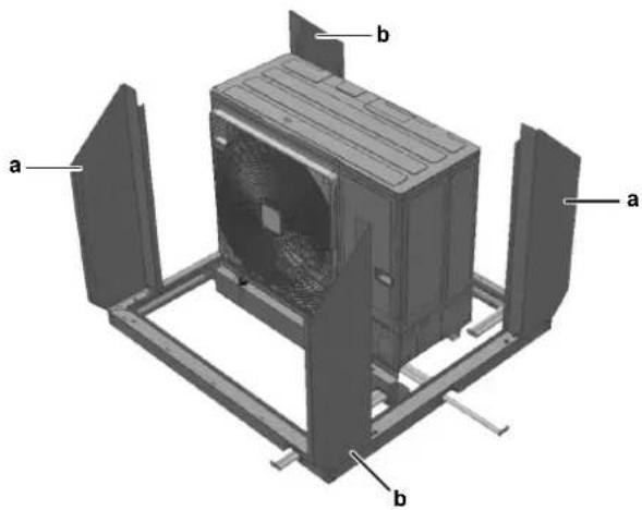
text_image
a b a b2 Fix with M5 Torx screws (accessory A) and washers (accessory B).

INFORMATION
Tighten them hand-tight (tightening torque <5N·m).
3 Fit the plastic guide pins (accessory M) to the bottom of the vertical support.
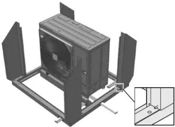
natural_image
3D rendering of a mechanical HVAC unit with mounting brackets and fan assembly (no text or symbols visible)4 Fix with M5 Torx screws (accessory A) and washers (accessory B).

INFORMATION
Tighten them hand-tight (tightening torque <5N·m).
5 Slide the 15×2.5 plastic spacer bush (accessory N) over the lower guide pins.
4.6 About installing the slats
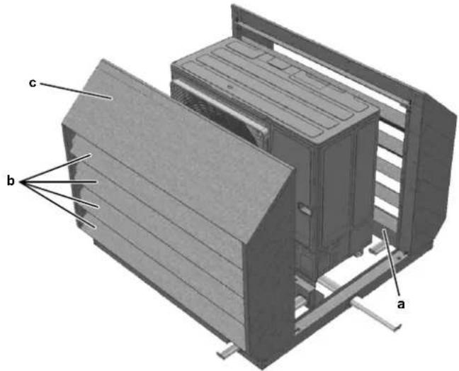
text_image
c b aa Lower slats (2×)
b Intermediate slats (8×)
c Upper slats (2×)
4.6.1 To install the lower slats
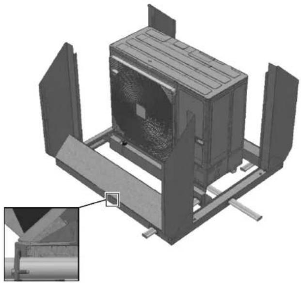
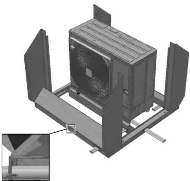
1 Tilt the mounting lips at the end of the slat so that they form a 90° angle with the slat.
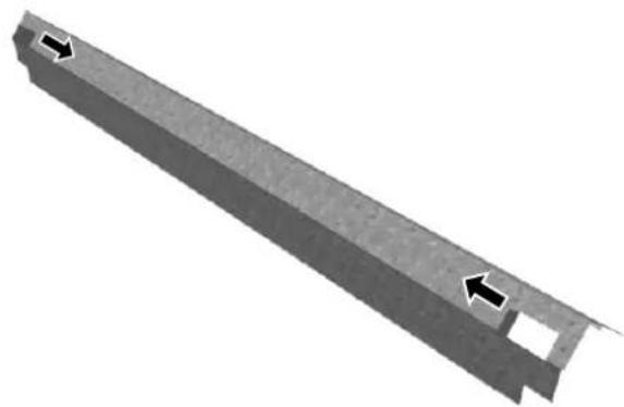
natural_image
3D rendering of a rectangular metal profile with two black arrows pointing to specific features (no text or symbols)4 Unit installation
2 Install the 2 lower slats.
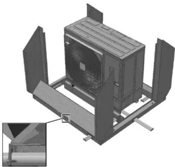
natural_image
3D mechanical assembly diagram showing a fan-like component mounted on a structural frame, with an inset close-up of a detail (no text or symbols visible)4.6.2 To install the intermediate slats
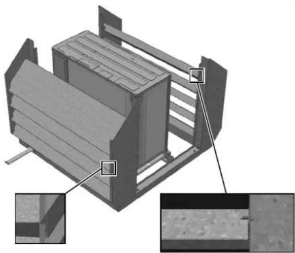
1 Tilt the intermediate slats into the vertical supports.
2 Position 4 intermediate slats on each side.
3 Bend the mounting lips 90° in respect of the slats.

INFORMATION
The lips MUST be connected to the vertical supports.
4 Hold the lip and vertical support firmly by hand to make sure that the holes align with one another.
5 Fix the lip with M5 Torx screws (accessory A) and washers (accessory B) inserted from outside.

INFORMATION
Tighten them hand-tight (tightening torque <5N·m).
natural_image
3D architectural rendering of a modular building structure with structural beams and panel supports (no text or symbols visible)4.6.3 To install the upper slats
1 Tilt the upper slats into the vertical supports.
2 Place the slat at the top over the vertical supports.
3 Slide the slat into the notches below in the vertical supports.
4 Fix the 8 guide pins (accessory M) with the M5 Torx screws (accessory A). A washer is NOT needed in this case.
5 Fit a 12×7 spacer bush (accessory O) over the upper guide pins (4×).
6 Fit the 4 additional M5 Torx screws (accessory A) and washers (accessory B).

INFORMATION
Tighten them hand-tight (tightening torque <5N·m).

natural_image
3D mechanical assembly diagram showing a housing with labeled components (a, b, c), no readable text or symbols present.a Guide pins (accessory M) with M5 Torx screw (accessory A)
b Spacer bush (accessory O)
c Additional M5 Torx screw (accessory A)
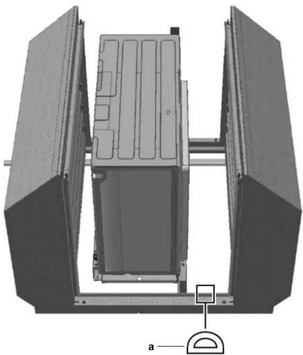
7 Fit the self-adhesive D-rubber (accessory P) to all edges of the vertical support, base frame, and upper slats.
8 Make sure the rubber is adhered flush with the outside of the sheet metal plate edges.

INFORMATION
Dry and degrease the sheet metal plate with a neutral cleaning agent to ensure that the D-rubber adheres properly. Cut the rubber to length with scissors.
natural_image
Technical diagram of a mechanical assembly with two symmetrical components and a central housing (no text or symbols visible)a Self-adhesive D-rubber (accessory P)
4.7 About installing the panels and sealing strips
4.7.1 To install the top panel
1 Position the top panel precisely over the 4 guide pins (accessory M).
2 Fix the top panel with 4× M5 Torx screws (accessory A) ONLY.

INFORMATION
Tighten them hand-tight (tightening torque <5N·m).
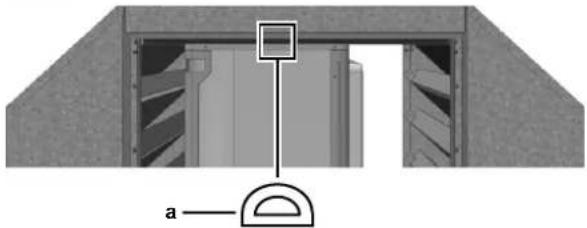
3 Fit the self-adhesive D-rubber (accessory P) to both edges of the top panel.
4 Make sure the rubber is adhered flush with the outside of the sheet metal plate edges.

INFORMATION
Dry and degrease the sheet metal plate with a neutral cleaning agent to ensure that the D-rubber adheres properly. Cut the rubber to length with scissors.
natural_image
Architectural cross-section diagram of a building facade with structural elements and a labeled component 'a' (no text or symbols beyond label)a Self-adhesive D-rubber (accessory P)
4.7.2 To install the side panels and sealing strips
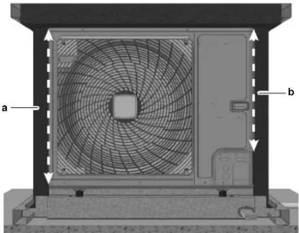
1 Affix the self-adhesive sealing strips to both sides of the outdoor unit.
natural_image
Technical diagram of a front-mounted air conditioning unit with labeled components (a and b), showing fan blades and control panel (no text or symbols beyond labels)a Sealing strip, left. Affix this over the full height of the outdoor unit (see dotted line).
b Sealing strip, right. Affix this over the length of the service door ONLY (see dotted line).
2 Push the remainder of the sealing strip between the base frame profile.
3 Lift the left and right side panels into the recess and let them slide over the lower pins (accessory M).

natural_image
Diagram of a solar panel installation process showing internal structure and two views of the panel (no text or symbols)4 Press the side panels tight and lock them with the key provided (accessory R).
Result: The low sound enclosure has been fitted.
5 Configuration
After installing the outdoor unit ALWAYS deactivate the high external static pressure function. This in order to avoid increased fan velocity and associated increase in outdoor unit sound emission.
| Model Setting Set to | value... | |
| RZAG71 | 2-79 2 | |
| RZAG100 | ||
| RZAG125 | ||
| RZAG140 | ||
| RZA200 | ||
| RZA250 | ||
| RXYSA4 | 2-18 | |
| RXYSA5 | ||
| RXYSA6 |

INFORMATION
For more information on the field settings, see the installer reference guide or the service manual of the outdoor unit.
6 Maintenance
- The low sound enclosure is free of maintenance under normal conditions.
- Clean the outside with water and a neutral cleaning agent at least twice a year to keep the housing in optimal condition.
- To avoid the short circuit of the airflow, ALWAYS keep the slats openings free from debris and remove dirt such as leaves and snow.

INFORMATION
For information on maintaining the outdoor unit, see the service manual for the respective outdoor unit.
Inhaltsverzeichnis
text_image
Technical diagram showing a mechanical assembly with labeled components and directional arrows, including a magnified inset of a tool interacting with a surface.natural_image
Pure geometric line drawing of a C-shaped structure with a base labeled 'a' (no text or symbols beyond label)natural_image
3D mechanical assembly diagram showing a frame with mounting holes and mounting points (no text or symbols)natural_image
Diagram of a rectangular frame with a small inset showing a cross-section labeled 'a', no text or symbols present.natural_image
3D mechanical assembly diagram showing a frame structure with mounting holes and a small inset view labeled 'a' (no text or symbols on the main structure)natural_image
3D rendering of a rectangular metal frame structure with internal structural components (no text or symbols)natural_image
3D diagram of a structural frame with mounting holes and internal supports, showing no text or symbols.natural_image
3D rendering of a mechanical housing assembly with fan and mounting brackets, showing internal components and a close-up inset detail (no text or symbols)natural_image
3D rendering of a mechanical part with two black arrows pointing to features, no text or symbols presentnatural_image
3D mechanical assembly diagram showing a fan-like component mounted on a structural frame, with an inset close-up of a cylindrical component (no text or symbols visible)natural_image
3D architectural rendering of a modular building structure with structural elements and panel details (no text or symbols)text_image
Technical diagram of a mechanical assembly with labeled components a, b, and c, showing internal structure and detail view.natural_image
Technical diagram of a mechanical assembly with two vertical plates and internal components, labeled 'a' (no text or symbols beyond label)natural_image
Architectural cross-section diagram showing structural components and a labeled dimension 'a' (no text or symbols beyond label)natural_image
Technical diagram of a fan or air conditioning unit with labeled components (a and b), showing internal blades and control panel (no text or symbols beyond labels)natural_image
Diagram of a solar panel installation process showing internal structure and two side views (no text or symbols)text_image
Technical diagram showing a mechanical assembly with labeled components and directional arrows, including a magnified inset of a tool or probe.natural_image
Pure geometric line drawing of a C-shaped structure with no text or symbolsnatural_image
3D mechanical assembly diagram showing a frame with four bolted joints and mounting points (no text or symbols)natural_image
3D diagram of a square frame with an inset showing a small rectangular object labeled 'a' (no text or symbols present)natural_image
3D mechanical assembly diagram showing a frame structure with mounting holes and a small inset view labeled 'a' (no text or symbols on the main structure)natural_image
3D rendering of a rectangular metal frame structure with internal structural components (no text or symbols)natural_image
3D mechanical frame structure with mounting holes and structural supports (no text or symbols)text_image
Technical diagram showing a mechanical or electrical component with labeled parts a, b, and c, including a central circular feature.natural_image
3D rendering of a mechanical housing with fan assembly and mounting brackets (no text or symbols visible)natural_image
3D rendering of a rectangular metal profile with two black arrows indicating features (no text or symbols)natural_image
3D rendering of a mechanical HVAC unit with fan assembly and structural brackets (no text or symbols visible)natural_image
3D architectural rendering of a modular building structure with structural details and cross-sectional views (no text or symbols)natural_image
3D mechanical assembly diagram showing internal components and a close-up inset of a textured surface (no text or symbols)natural_image
Technical diagram of a mechanical assembly with two vertical plates and internal components, labeled 'a' (no text or symbols on the diagram itself)a Caoutchouc en D autocollant (accessoire P)
natural_image
Architectural cross-section diagram showing structural elements and a labeled component 'a' (no text or symbols beyond label)a Caoutchouc en D autocollant (accessoire P)
natural_image
Technical diagram of a mechanical fan or air conditioning unit with labeled components (a and b), showing internal blades and mounting base (no text or symbols beyond labels)natural_image
Diagram of a device with internal components and directional arrows, showing two views of the panel (no text or symbols present)text_image
Diagram illustrating a mechanical or structural assembly with labeled components and directional arrows, including a magnified inset showing a tool interacting with a surface.a Afdichtingstape (accessoire C)
natural_image
Pure geometric line drawing of a C-shaped structure with a base labeled 'a' (no text or symbols beyond label)a Afdichtingstape (accessoire C)
natural_image
3D mechanical assembly diagram showing a frame with mounting holes and mounting points (no text or symbols)natural_image
Diagram of a rectangular frame with a small inset showing a 3D object labeled 'a' (no text or symbols present)natural_image
3D mechanical assembly diagram showing a frame structure with mounting holes and a small inset view labeled 'a' (no text or symbols on the main structure)natural_image
3D rendering of a rectangular metal frame structure with internal structural components (no text or symbols)natural_image
3D mechanical assembly diagram showing a rectangular frame with mounting holes and three internal components, no text or symbols present.natural_image
3D mechanical assembly diagram showing a fan-like component mounted on a frame, with an inset close-up of a detail (no text or symbols visible)natural_image
3D rendering of a rectangular structural component with two black arrows indicating features (no text or symbols)natural_image
3D mechanical assembly diagram showing a fan-like component mounted on a frame, with an inset close-up of a cylindrical component (no text or symbols visible)4.6.2 De tussenliggende lamellen installeren
natural_image
3D architectural rendering of a modular building structure with structural details and cross-sectional views (no text or symbols)text_image
Technical diagram of a mechanical assembly with labeled components a, b, and c, showing internal structure and detail view.natural_image
Technical diagram of a mechanical assembly with two vertical plates and internal components, labeled 'a' (no text or symbols on the diagram itself)a Zelfklevend D-rubber (accessoire P)
natural_image
Architectural cross-section diagram showing structural components and a labeled dimension 'a' (no text or symbols beyond label)a Zelfklevend D-rubber (accessoire P)
natural_image
Technical diagram of a fan or air conditioning unit with labeled components (a and b), showing internal blades and structural details (no text or symbols beyond labels)natural_image
Diagram of a solar panel installation process showing cooling and drying stages with directional arrows (no text or symbols)text_image
Technical diagram showing a mechanical assembly with labeled components and directional arrows, including a magnified inset of the component.natural_image
Pure geometric line drawing of a C-shaped structure with no text or symbolsnatural_image
3D mechanical assembly diagram showing a frame with four bolted joints and mounting points (no text or symbols)natural_image
Diagram of a square frame with a small inset showing a cross-section labeled 'a', no text or symbols present.natural_image
3D mechanical assembly diagram showing a frame structure with mounting holes and a small inset view labeled 'a' (no text or symbols present)natural_image
3D rendering of a rectangular metal frame structure with internal structural components (no text or symbols)natural_image
3D diagram of a rectangular metal frame with mounting holes and mounting points (no text or symbols)natural_image
3D rendering of a mechanical HVAC unit mounted on a frame, with an inset showing a close-up detail (no text or symbols visible)natural_image
3D rendering of a structural beam with two directional arrows indicating force or movement (no text or symbols)natural_image
3D rendering of a mechanical housing with fan and structural supports, showing internal components and a close-up inset (no text or symbols)natural_image
3D architectural rendering of a modular building structure with structural elements and cross-sectional details (no text or symbols)natural_image
3D mechanical assembly diagram showing internal components and a close-up inset of a textured surface (no text or symbols)natural_image
Technical diagram of a mechanical assembly with two symmetrical components and a labeled component 'a' (no text or symbols beyond label)natural_image
Architectural cross-section diagram showing structural components and a labeled section 'a' (no text or symbols beyond label)natural_image
Technical diagram of a large air conditioning unit with labeled components (a and b), showing fan blades and internal structure (no text or symbols beyond labels)natural_image
Diagram of a device with internal components and directional arrows, showing two views of the panel (no text or symbols present)text_image
Technical diagram showing a mechanical assembly with labeled components and directional arrows indicating motion or force.a Nastro sigillante (accessorio C)
natural_image
Pure geometric line drawing of a C-shaped structure with a base labeled 'a' (no text or symbols beyond label)a Nastro sigillante (accessorio C)
natural_image
3D mechanical assembly diagram showing a frame with mounting holes and mounting points (no text or symbols)natural_image
Diagram of a rectangular frame with a small inset showing a cross-section labeled 'a', no text or symbols present.natural_image
3D mechanical assembly diagram showing a frame structure with mounting holes and a small inset view labeled 'a' (no text or symbols on the main structure)natural_image
3D rendering of a rectangular metal frame structure with internal supports and mounting holes (no text or symbols)natural_image
3D diagram of a structural frame with mounting holes and internal supports (no text or symbols)natural_image
3D mechanical assembly diagram showing a fan-like component mounted on a frame, with an inset close-up of a detail (no text or symbols visible)natural_image
3D rendering of a mechanical part with two black arrows indicating features (no text or symbols)2 Installare le 2 lastre inferiori.
natural_image
3D mechanical assembly diagram showing a fan mounted on a structural frame with mounting brackets (no text or symbols visible)natural_image
3D architectural rendering of a modular building structure with structural details and cross-sectional views (no text or symbols)natural_image
3D mechanical assembly diagram showing internal components and a close-up view of a component with labeled parts (a, b, c), no readable text or symbols present.natural_image
Technical diagram of a mechanical assembly with two symmetrical components and a labeled component 'a' (no text or symbols beyond label)a Gomma D autoadesiva (accessorio P)
natural_image
Architectural cross-section diagram showing structural components and a labeled section 'a' (no text or symbols beyond label)a Gomma D autoadesiva (accessorio P)
natural_image
Technical diagram of a fan or air conditioning unit with labeled components (a and b), showing internal blades and control panel (no text or symbols beyond labels)natural_image
Diagram of a device with internal components and directional arrows, showing two views of the panel (no text or symbols present)text_image
Technical diagram showing a mechanical assembly with labeled components and directional arrows, including a magnified inset of a tool or probe.natural_image
Pure geometric line drawing of a C-shaped structure with a base labeled 'a' (no text or symbols beyond label)natural_image
3D mechanical assembly diagram showing a frame with mounting holes and mounting points (no text or symbols)natural_image
Diagram of a square frame with an inset showing a small rectangular object labeled 'a' (no text or symbols present)natural_image
3D mechanical assembly diagram showing a frame structure with mounting holes and a small inset view labeled 'a' (no text or symbols present)natural_image
3D rendering of a rectangular metal frame structure with mounting holes and internal structural elements (no text or symbols)natural_image
3D diagram of a structural frame with mounting holes and internal supports (no text or symbols)natural_image
3D mechanical assembly diagram showing a fan-like component mounted on a frame, with an inset close-up highlighting a small feature (no text or symbols present)natural_image
3D rendering of a mechanical part with two black arrows indicating features (no text or symbols)natural_image
3D mechanical assembly diagram showing a fan-like component mounted on a structural frame, with an inset close-up of a cylindrical component (no text or symbols visible)natural_image
3D architectural rendering of a modular building structure with structural details and cross-sectional views (no text or symbols)natural_image
3D mechanical assembly diagram showing internal components and a close-up inset of a textured surface (no text or symbols)natural_image
Technical diagram of a mechanical assembly with two vertical plates and internal components, labeled 'a' (no text or symbols beyond label)natural_image
Architectural cross-section diagram of a building facade with structural elements and a labeled component 'a' (no text or symbols beyond label)natural_image
Technical diagram of a large air conditioning unit with fan blades and labeled components (a and b), no readable text or symbols beyond labels.natural_image
Diagram of a solar panel installation process showing internal structure and two side views (no text or symbols)text_image
Technical diagram showing a mechanical assembly with labeled components and directional arrows, including a magnified inset of a tool or probe.natural_image
Pure geometric diagram of a bent pipe or channel with labeled point 'a' (no text or symbols beyond label)natural_image
3D mechanical assembly diagram showing a frame with mounting holes and mounting points (no text or symbols)natural_image
Diagram of a square frame with a small inset showing a cross-section labeled 'a', no text or symbols present.natural_image
3D mechanical assembly diagram showing a frame structure with mounting holes and a small inset view labeled 'a' (no text or symbols on the main structure)natural_image
3D rendering of a rectangular metal frame structure with internal structural components (no text or symbols)4.2.3 Acerca de instalar a unidade de exterior

INFORMAÇÕES
natural_image
3D diagram of a structural frame with mounting holes and internal supports, showing no text or symbols.natural_image
3D mechanical assembly diagram showing a fan-like component mounted on a frame, with an inset close-up of a detail (no text or symbols visible)natural_image
3D rendering of a rectangular structural component with two black arrows indicating features (no text or symbols)2 Instale os 2 encaixes inferiores.
natural_image
3D mechanical assembly diagram showing a fan-like component mounted on a structural frame, with an inset close-up of a cylindrical component (no text or symbols visible)4.6.2 Para instalar os encaixes intermédios
natural_image
3D architectural rendering of a modular building structure with structural details and cross-sectional views (no text or symbols)4.6.3 Para instalar os encaixes superiores
natural_image
3D mechanical assembly diagram showing a housing component with labeled parts (a, b, c), no readable text or symbols present.natural_image
Technical diagram of a mechanical assembly with two vertical plates and internal components, labeled 'a' (no text or symbols on the diagram itself)a Borracha D autoadesiva (acessório P)
natural_image
Architectural cross-section diagram showing structural components and a labeled dimension 'a' (no text or symbols beyond label)a Borracha D autoadesiva (acessório P)
natural_image
Technical diagram of a mechanical fan or air conditioning unit with labeled components (a and b), showing internal blades and mounting base (no text or symbols beyond labels)natural_image
Diagram of a solar panel installation process showing cooling and drying stages with directional arrows (no text or symbols)text_image
Technical diagram showing a mechanical assembly with labeled components and directional arrows, including a magnified inset of a tool or probe.natural_image
Pure geometric line drawing of a C-shaped structure with no text or symbolsnatural_image
3D mechanical assembly diagram showing a frame with mounting holes and mounting points (no text or symbols)natural_image
Diagram of a square frame with a small inset showing a cross-section labeled 'a', no text or symbols present.natural_image
3D mechanical assembly diagram showing a frame structure with mounting holes and a small inset view labeled 'a' (no text or symbols on the main structure)natural_image
3D rendering of a structural frame with mounting holes and internal supports (no text or symbols)natural_image
3D diagram of a structural frame with mounting holes and internal supports (no text or symbols)natural_image
3D rendering of a mechanical fan assembly with mounting brackets and a close-up inset showing a detail (no text or symbols)natural_image
3D rendering of a rectangular metal profile with two black arrows pointing to specific features (no text or symbols)natural_image
3D mechanical assembly diagram showing a fan-like component mounted on a structural frame, with an inset close-up of a cylindrical component (no text or symbols visible)natural_image
3D architectural rendering of a modular building structure with structural details and cross-sectional views (no text or symbols)natural_image
3D mechanical assembly diagram showing internal components and a close-up inset of a textured surface (no text or symbols)natural_image
Technical diagram of a mechanical assembly with two vertical plates and internal components, labeled 'a' (no text or symbols on the diagram itself)natural_image
Architectural cross-section diagram of a building facade with structural elements and a labeled component 'a' (no text or symbols beyond label)natural_image
Technical diagram of a fan or air conditioning unit with labeled components (a and b), showing internal blades and control panel (no text or symbols beyond labels)natural_image
Diagram of a solar panel installation process showing internal structure and two views of the panel (no text or symbols)text_image
Technical diagram showing a mechanical assembly with labeled components and directional arrows indicating motion or force.natural_image
Pure geometric line drawing of a C-shaped structure with a base labeled 'a' (no text or symbols beyond label)natural_image
3D mechanical assembly diagram showing a frame with mounting holes and mounting points (no text or symbols)natural_image
Diagram of a square frame with a small inset showing a cross-section labeled 'a', no text or symbols present.natural_image
3D mechanical assembly diagram showing a frame structure with mounting holes and a small inset view labeled 'a' (no text or symbols on the main structure)natural_image
3D rendering of a rectangular metal frame structure with internal structural components (no text or symbols)natural_image
3D diagram of a rectangular frame with mounting holes and internal structural elements, no text or symbols presentnatural_image
3D rendering of a mechanical fan assembly with mounting brackets and a close-up inset showing a small component (no text or symbols)4 M5 Torx vidalar (aksesuar A) ve rondelalarla (aksesuar B) sabitleyin.

BİLGİ
natural_image
3D rendering of a rectangular metal profile with two black arrows pointing to specific features (no text or symbols)4 Ünitenin montajı
natural_image
3D mechanical assembly diagram showing a fan-like component mounted on a structural frame, with an inset close-up of a detail (no text or symbols visible)natural_image
3D architectural rendering of a modular building structure with structural details and cross-sectional views (no text or symbols)natural_image
3D mechanical assembly diagram showing internal components and a close-up inset of a component detail (no text or symbols)a M5 Torx vidalarla (aksesuar A) kılavuz pimleri (aksesuar M)
b Ara parçası burcu (aksesuar O)
c Ek M5 Torx vida (aksesuar A)