
LZV2622BW - Surveillance Camera Lorex - Free user manual and instructions
Find the device manual for free LZV2622BW Lorex in PDF.

| Product Type | PTZ Surveillance Camera |
| Brand | Lorex |
| Model | LZV2622BW |
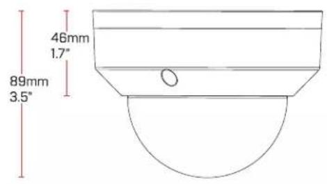
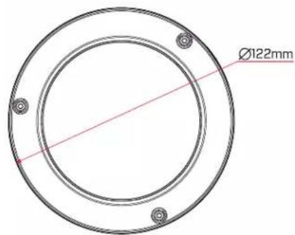
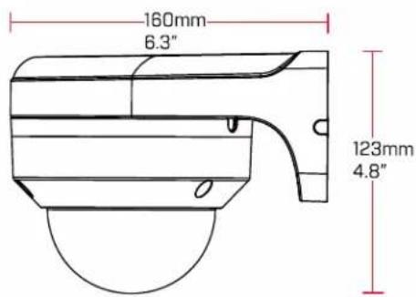
| Dimensions (camera only) | Ø160 x 123 mm |
| Weight (camera only) | 0.54 kg |
| Weight (with wall mount) | 1.06 kg |
| Power Supply | 12 V DC, max 600 mA |
| Max Resolution | 1080p (1928 x 1088 pixels) |
| Sensor | CMOS 1/2.7", 2.1 MP |
| Night Vision | Yes, with IR filter, 0.1 Lux (color), 0.05 Lux (B&W) |
| Zoom | Optical 4x, digital 16x |
| Horizontal View Angle | 95° to 30° |
| Pan Movement | 0° to 355°, max speed 80°/s |
| Tilt Movement | 0° to 90°, max speed 40°/s |
| Connectivity | BNC video, DC power, RS485 (service) |
| Protection Rating | IP66 (indoor/outdoor) |
| Operating Temperature | -30°C to 60°C |
| Operating Humidity | Relative humidity < 95% |
| Maintenance and Cleaning | Clean the dome with a damp cloth only, no chemicals |
| Safety | Use only the supplied adapter; do not expose to rain; disconnect before installation |
| Included Accessories | 60 ft (18.2 m) extension cable, 12 V adapter, wall mount, screws, Allen keys |
| Repairability | No user-serviceable parts; contact a qualified technician |
Frequently Asked Questions - LZV2622BW Lorex
User questions about LZV2622BW Lorex
0 question about this device. Answer the ones you know or ask your own.
Ask a new question about this device
Download the instructions for your Surveillance Camera in PDF format for free! Find your manual LZV2622BW - Lorex and take your electronic device back in hand. On this page are published all the documents necessary for the use of your device. LZV2622BW by Lorex.
USER MANUAL LZV2622BW Lorex
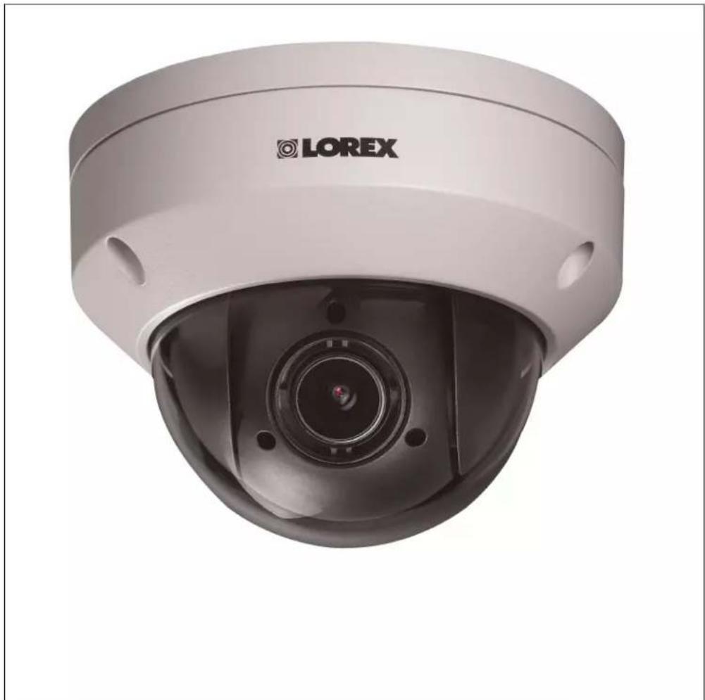
Instruction Manual LZV2622 SERIES 4x MPX PTZ DOME CAMERA
natural_image
Front view of a LOREX security camera with a central lens (no visible text or symbols beyond branding)LZV2622_SERIES_MANUAL_TRILINGUAL_R4
Thank you for purchasing this product. Lorex is committed to providing our customers with a high quality, reliable security solution.
This manual refers to the following model:
LZV2622
For the latest online manual, downloads and product updates, and to learn about our complete line of accessory products, please visit our website at:
www.lorextechnology.com
WARNING
RISK OF ELECTRIC SHOCK DO NOT OPEN
WARNING: TO REDUCE THE RISK OF ELECTRIC SHOCK DO NOT REMOVE COVER. NO USER SERVICEABLE PARTS INSIDE.
REFER SERVICING TO QUALIFIED SERVICE PERSONNEL.
The lightning flash with arrowhead symbol, within an equilateral triangle, is intended to alert the user to the presence of uninsulated "dangerous voltage" within the product's enclosure that may be of sufficient magnitude to constitute a risk of electric shock.
The exclamation point within an equilateral triangle is intended to alert the user to the presence of important operating and maintenance (servicing) instructions in the literature accompanying the appliance.
WARNING: TO PREVENT FIRE OR SHOCK HAZARD, DO NOT EXPOSE THIS UNIT TO RAIN OR MOISTURE.
CAUTION: TO PREVENT ELECTRIC SHOCK, MATCH WIDE BLADE OF THE PLUG TO THE WIDE SLOTAND FULLY INSERT.
Table of contents
1 Safety Instructions ....1
2 Getting Started....2
3 Connecting the Camera....3
4 Installation ....4
4.1 Installation Tips and Warnings ....4
4.2 Extension Cables....4
4.2.1 Cable Extension Options ....4
4.2.2 Connection Diagram for Extending the Cables Beyond 60ft (18.2m)....5
4.3 Installation (Indoor/Outdoor)....5
4.3.1 Wall Mounting 6
4.3.2 Ceiling Mounting 10
5 Controlling the PTZ Camera with your MPX DVR.... 11
5.1 Controlling a PTZ Camera (Local DVR).... 11
5.2 Advanced PTZ Controls 13
5.2.1 Presets 13
5.2.2 Tours.... 14
5.2.3 Pattern.... 15
6 Technical Specifications.... 16
6.1 Dimensions 16
7 Troubleshooting 18
8 Notices.... 19
8.1 FCC/IC Notice.... 19
8.2 Modification.... 19
8.3 ROHS 19
1
Safety Instructions
- Read this guide carefully and keep it for future reference.
- Follow all instructions for safe use of the product and handle with care.
- Use the camera within given temperature, humidity, and voltage levels noted in the Technical Specifications.
- Camera is rated for outdoor use and is weatherproof when properly installed. Camera is not intended for submersion in water. Installation under a sheltered environment is recommended.
- Do not disassemble the camera.
- Do not point the camera directly towards the sun or a source of intense light.
- Use only the supplied regulated power supply. Use of a non-regulated, non-conforming power supply can damage this product and voids the warranty.
- Make sure to install the camera in a location that can support the camera weight.
- Make sure there are no live electrical cables in the area where you plan to mount the camera.
- Periodic cleaning may be required. Use a damp cloth only. Do not use anything other than water to clean the dome cover, as chemicals such as acetone can permanently damage the plastic.
2
Getting Started
The system comes with the following components:
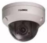 MPX PTZ Dome Camera MPX PTZ Dome Camera | 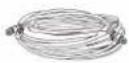 60ft (18.2m) UL Rated Extension Cable 60ft (18.2m) UL Rated Extension Cable | 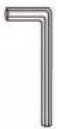 Allen Key (x2)(One included in the mounting hardware kit of the camera, and one included in the mounting hardware kit of the wall mounting bracket) Allen Key (x2)(One included in the mounting hardware kit of the camera, and one included in the mounting hardware kit of the wall mounting bracket) |
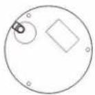 Mounting Template Mounting Template | 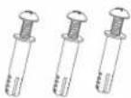 Mounting Screws (x3)& Anchors (x3)(For camera) Mounting Screws (x3)& Anchors (x3)(For camera) | 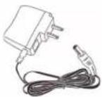 12V DC Power Adapter 12V DC Power Adapter |
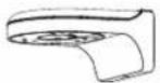 Wall Mounting Bracket Wall Mounting Bracket | 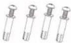 Mounting Screws ST4 (x4)& Anchors S6 (x4)(For wall mounting bracket) Mounting Screws ST4 (x4)& Anchors S6 (x4)(For wall mounting bracket) | 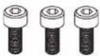 Hex Bolt M4x10 (x3)(For wall mounting bracket) Hex Bolt M4x10 (x3)(For wall mounting bracket) |
 Installation Diagram Guide and Instructional Manual Installation Diagram Guide and Instructional Manual |
3
Connecting the Camera
flowchart
graph LR
    A["Camera"] --> B["RS-485"]
    B --> C["BNC"]
    C --> D["12V DC"]
    D --> E["Extension Cable"]
    E --> F["DVR"]
    F --> G["Switch"]
    G --> H["Output"]
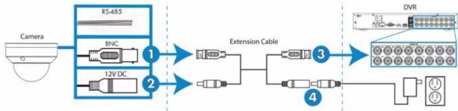
- Connect the BNC video connector on the camera cable to the included extension cable.
- Connect the female 12V DC power connector on the camera cable to the male power connector on the included extension cable.
- Connect the BNC cable on the extension cable to one of the Video Input ports on the DVR. Make note of the port number where you connect the camera, as it will be used when configuring the DVR to communicate with the camera.
- Connect the power connector on the extension cable to the included power adapter. Plug the power adapter into a power outlet.

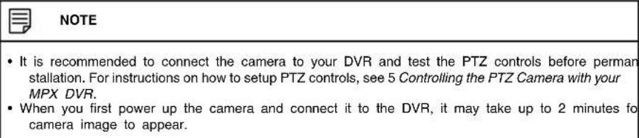
CAUTION
- Make sure to disconnect the power adapter before installing the camera. The camera will begin moving immediately when the power adapter is connected.
| NOTE |
| RS-485 is for service purposes only — not required for controlling MPX PTZ cameras. |
4
Installation
4.1 Installation Tips and Warnings
- Camera is rated for outdoor use. It is recommended to install the camera in a sheltered area, such as under the eaves on a roof.
- Use the included wall mounting bracket for wall installation. Otherwise, the camera image will be sideways. You can also refer to the included installation diagram guide for wall mounting instructions.
- Camera is capable of seeing in low light conditions (0.1 Lux), but it cannot see in total darkness.

NOTE
It is recommended to install the camera where there is some ambient light (for example, street lighting or starlight, moonlight, etc.) or leave some lighting on in the area where the camera is installed.
- Mount the camera in a location that can support the camera weight.
- Mount the camera where the lens is away from direct and intense sunlight.
- Ensure you adhere to local building codes.
- Ensure that the camera wiring is not exposed or easily cut.
- Mount the camera in an area that is visible but out of reach.
- Plan your cable wiring so that it does not interfere with power lines or telephone lines.

NOTE
This camera is suitable for ceiling mounting. Wall mounting requires included wall mount.
4.2 Extension Cables
- The included extension cable is 60ft (18.2m) long. If you are planning on extending the camera's video cabling beyond 60ft (18.2m), see 4.2.2 Connection Diagram for Extending the Cables Beyond 60ft (18.2m).
- Because this is a high-powered PTZ camera, the power cable cannot be extended beyond 60ft (18.2m). You may connect the included power adapter directly to the camera's power connector and plug the adapter into a power outlet near the camera.
- The RS-485 wires on the camera cable are for service purposes only.
- You can extend the camera's video with a single cable run of up to 800ft / 242m long (not included). Video quality may decrease if your extension cable is too long. For this setup, you must purchase a single run of RG59 coaxial extension cable. It is recommended to use a video cable with the following specification: RG59U 95% Braid 20AWG or better.

NOTE
RG59 coaxial cable should be available from your local building supply store.
4.2.1 Cable Extension Options
Extend the cable run for your camera depending on the cable type used. Additional extension cables sold separately. See table below:
| Option Cable Type Max Cable | Run Distance | |
| 1 | Lorex 60ft (18.2m) BNC / DC Cable(Included with camera) | 60ft (18.2m) |
| 2 | ‘RG59’ or ‘Coax’ or ‘Coaxial BNC'Siamese (Video and Power) | 300ft / 92m |
| 3 | ‘RG59’ or ‘Coax’ or ‘Coaxial BNC'(Video Only ^2 ) | 800ft / 242m |
| NOTE |
| 1. The extension cable must be a single stretch of cable between the recorder and camera. You cannot connect multiple extension cables to each other.2. For cable runs above 300ft / 92m (option 3), you must connect the power adapter directly to the camera, rather than at the end of the extension cable.3. Indicators that your cable run may be too long:Video is permanently black & white (even during day time)Video is unclear, soft, or distorted4. For more information on extension cables, visitwww.lorextechnology.com/compatibility |
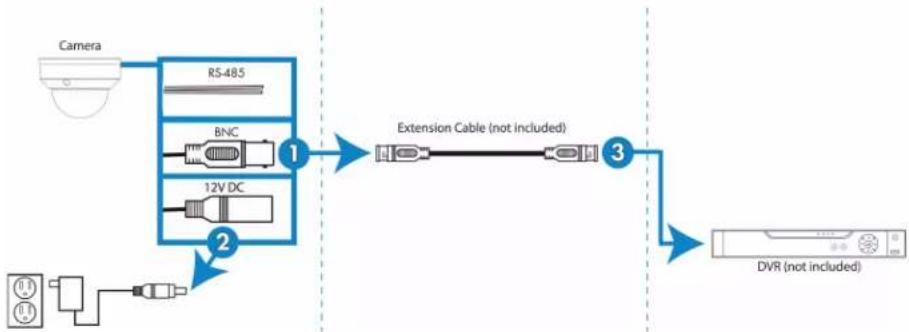
4.2.2 Connection Diagram for Extending the Cables Beyond 60ft (18.2m)
flowchart
graph LR
    A["Camera"] --> B["RS-485"]
    B --> C["BNC"]
    C --> D["12V DC"]
    D --> E["Extension Cable (not included)"]
    E --> F["DVR (not included)"]
    G["Sensor"] --> H["Ground"]
    I["External Portugal"] --> J["Switch"]
    K["External Portugal"] --> L["Switch"]
    M["External Portugal"] --> N["Switch"]
    O["External Portugal"] --> P["Switch"]
- Connect the BNC video connector on the camera cable to a single BNC extension cable up to 800ft / 242m long (not included).
- Connect the female 12V DC power connector on the camera cable to the included power adapter. Connect the power adapter to a power outlet.
| CAUTION |
| Make sure to disconnect the power adapter before installing the camera. The camera will be moving immediately when the power adapter is connected. |
- Connect the BNC extension cable to one of the Video Input ports on the DVR. Make note of the port number where you connect the camera, as it will be used when configuring the DVR to communicate with the camera.
4.3 Installation (Indoor/Outdoor)
The camera includes all necessary components for ceiling mounting and wall mounting. For full instructions on each type of mounting, see 4.3.1 Wall Mounting or 4.3.2 Ceiling Mounting.
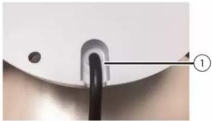
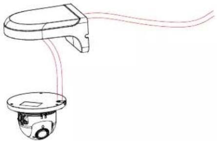
Before installing the camera, decide whether to run the cables through the wall / ceiling (drilling required) or along the wall / ceiling. If you run the cables along the wall / ceiling, you must run the cable through the cable notch on the dome camera base. This will keep the dome camera base flush to the ceiling when mounted.
natural_image
Close-up of a medical or surgical tool with a black cable inserted into a white circular component, labeled with number 1 (no text or symbols on the tool itself)- Cable Notch
4.3.1 Wall Mounting

CAUTION
Make sure to install in a location that can support the combined weight of the wall mounting bracket and the camera.
To wall mount the camera:
- Use the Allen key (S3.0) included with the wall mounting bracket kit to loosen the hex lock on the bottom of the wall mounting bracket. Once loose, remove the back plate of the mounting bracket.
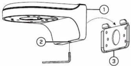
- Wall Mount
- Hex Lock
-
Back Plate
-
Use the Allen key included with the camera mounting kit to loosen the dome camera cover screws (x3). Remove the dome camera cover.
-
Insert the camera cable through the hole in the wall mounting bracket.
natural_image
Line drawing of a handheld device with a circular base and cable routing (no text or symbols)- Ensure that the cable notch on the dome camera base is aligned with the cable notch on the wall mounting bracket. Align the 3 mounting holes on the dome camera base with the 3 corresponding mounting holes on the wall mounting bracket.
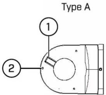
1: Cable Notch
2: Mounting Holes

NOTE
The wall mount you received may have more or less mounting holes than the one depicted in this guide. The mounting holes (3x) on the dome camera base will align with the corresponding mounting holes on the wall mount.
-
Use the Hex Bolt M4x10 (x3) screws included with the wall mounting bracket kit to secure the position of the dome camera base.
-
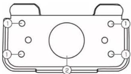
Holding the flat side of the back plate against the mounting surface, mark holes for the mounting screws ST4 (x4) and the camera cable. Remove the back plate and drill where marked.

NOTE
You do not need to mark holes for the camera cable if you plan to run it along the wall / ceiling.
natural_image
Technical line drawing of a mechanical component with labeled parts (no text or symbols)1: Mounting screw ST4 (x4) holes, 2: Camera cable hole
- Attach the back plate to the mounting surface using the mounting screws ST4 (x4) included with the wall mounting bracket kit.

NOTE
Use the drywall anchors included with the wall mounting bracket kit if installing on a drywall surface.
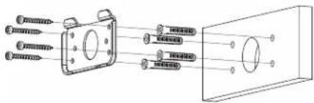
- Connect the camera cables as shown in the 3 Connecting the Camera section, then feed the cables through the cable hole in the back plate (attached to the mounting surface).
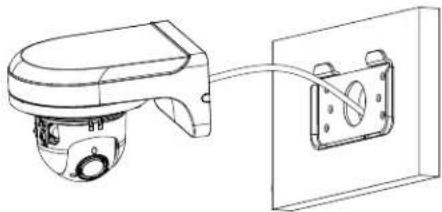
natural_image
Technical line drawing of a mechanical device connected to a wall-mounted bracket (no text or symbols)
CAUTION
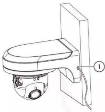
If you run the cables along the mounting surface, you must run the cable through the side notch on the wall mounting bracket. The camera cable will hang alongside the wall mounting bracket — see image below for reference:
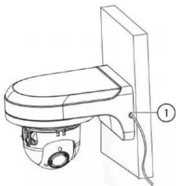
natural_image
Technical line drawing of a toilet with a base and wall-mounted panel, labeled with number 1 (no text or symbols on the diagram itself)-
Side Notch
-
Lower the wall mounting bracket onto the back plate. Ensure that the 2 metal flaps on the back plate lock into the 2 grooves in the wall mounting plate.
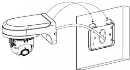
natural_image
Technical line drawing of a mechanical device with attached components and wiring (no text or symbols)Installation4
- Use the included Allen key (S3.0) to tighten the hex lock on the bottom of the wall mounting bracket.
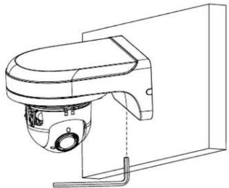
natural_image
Technical line drawing of a mechanical device mounted on a wall, showing no text or symbols.- Replace the dome camera cover and tighten the dome camera cover screws using the Allen key included with the camera mounting kit.
- Remove the vinyl film from the dome cover once installation is complete.
4.3.2 Ceiling Mounting
To ceiling mount the camera:
- Use the mounting template included with the camera mounting kit to mark holes for the mounting screws (x3) and camera cable.
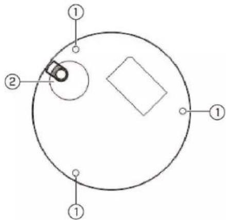
-
Mounting screw holes; 2. Camera cable hole (Optional)
-
Drill holes for the mounting screws, drywall anchors (optional) and camera cable (optional).
| NOTE |
| ·Use the included drywall anchors if installing on a drywall surface.·If you are planning on running the cables along the mounting surface, there is no need to do hole for the camera cable. |
- Use the Allen key included with the camera mounting kit to loosen the dome camera cover screws (x3). Remove the dome camera cover.
- Connect the camera cables as shown in 3 Connecting the Camera.
- Mount the dome camera base to the mounting surface using the mounting screws (x3) and drywall anchors (x3) (optional) included with the camera mounting kit.
- Replace the dome camera cover and tighten the dome camera cover screws using the included Allen key.
- Remove the vinyl film from the dome cover once installation is complete.
Controlling the PTZ Camera with your MPX DVR
You can connect the PTZ camera to a MPX DVR to control the camera's movement. The camera can accept PTZ commands directly through the video cable (MPX only), so there is no need to run special wiring (for example, RS-485).
| NOTE |
| For the latest list of compatible DVRs, please visit www.lorextechnology.com/compatibility. |
To connect the PTZ camera to a DVR:
- Connect the camera video cable to one of the Video IN ports on the DVR system as detailed in 3 Connecting the Camera.
-
Right-click and click Main Menu. Enter the system user name (default: admin) and password (default: 000000) if prompted.
-
Click >SETTING>PAN/TILT/ZOOM.
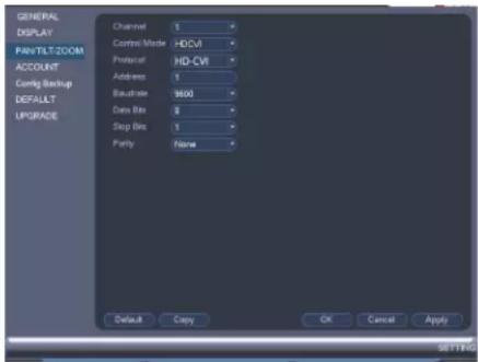
- Under Channel, select the channel your PTZ camera is connected to.
- Under Control Mode, select HDCVI.
- Under Protocol, select HD-CVI.
- Click OK. You can now control your PTZ camera using the system.
5.1 Controlling a PTZ Camera (Local DVR)
- In Live View, double-click the channel that has the PTZ camera connected to open in full-screen.
- Right-click and click Pan/Tilt/Zoom. Enter the system user name and password if prompted. The PTZ menu opens.
- Use the on-screen PTZ controls to control the camera.
PTZ Controls
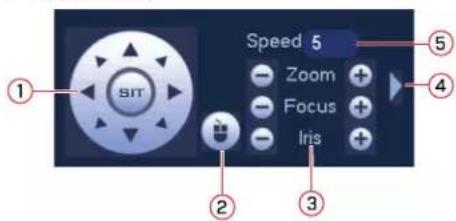
-
Direction keys: Click to pan and tilt the camera. Click SIT to stop the current action.
-
PTZ Trace: Click to activate PTZ trace mode. You can do the following:
-
Click and drag to move the camera.
- Use the scroll wheel to zoom in and out.
-
Right-click to exit and return to normal PTZ controls.
-
Zoom / Focus / Iris: Click +/- to adjust the zoom, focus, and iris.
- Advanced controls: Click to open advanced PTZ controls.
- Speed: Enter a PTZ speed from 1 (slowest) to 8 (fastest).
5.2 Advanced PTZ Controls
Advanced PTZ controls can be used to save camera positions and cycle through various positions, and automate camera actions.
To open advanced PTZ controls:
- Click the arrow in the PTZ control window to open advanced controls.
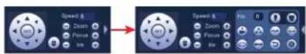
Advanced PTZ controls overview:
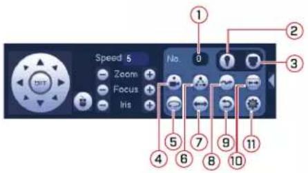
- No.: Select the number of the action you want to perform.
- Not supported.
- PTZ camera menu: Click to open the camera's OSD menu. This menu is for advanced users only.
- Preset: Click to move the camera to the selected preset location.
- Not supported.
- Tour: Click to run the selected tour.
- Not supported.
- Pattern: Click to run the selected pattern.
- Not supported.
- Not supported.
- Click to open the PAN/TILT/ZOOM menu, where you can set up Presets, Tours, and Patterns.

5.2.1 Presets
Presets will save the camera's position for quick retrieval.
To add presets:
-
Click 📋 to open the PAN/TILT/ZOOM menu.
-
Click the Preset tab.
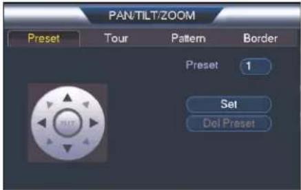
- Enter the number of the preset you want to create under Preset.
- Move the camera to the desired position and click Set.
- Right-click to return to the advanced PTZ controls window.
To go to a preset:
• Under No., select the number of the preset you would like to go to and click

5.2.2 Tours
Tours will cycle through a set of presets.
To create a tour:
- Click 🔍 to open the PAN/TILT/ZOOM menu.
- Click the Tour tab.
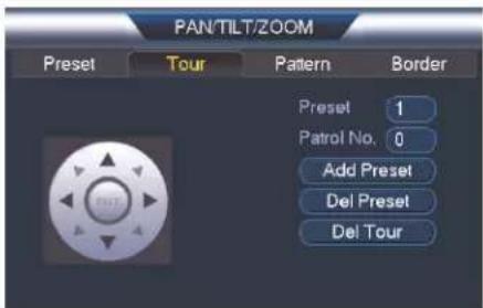
- Under Patrol No., select the tour you would like to configure.
- Under Preset, select a preset you would like to add to the tour.
- Click Add Preset.
- Repeat steps 4 and 5 to add additional presets to the tour.
| NOTE |
| Click Del Tour to clear all presets from a tour. |
- Right-click to return to the advanced PTZ controls window.
To run a tour:
• Under No., select the number of the tour you would like to go to and click


NOTE
- There is a 5 second minimum pause between presets.
- Tour panning / tilting speed is slower than manual panning / tilting speed. The reduced speed maximizes reliability.
- The camera's full panning range is 355^ . However, we recommend you do not make the camera pan more than 270^ between any two points in a tour.
5.2.3 Pattern
Patterns automatically cycle the camera between two positions.
To create a pattern:
- Click 🔒 to open the PAN/TILT/ZOOM menu.
- Click the Pattern tab.
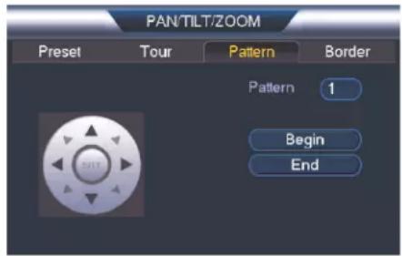
- Under Pattern, enter the pattern you would like to configure.
- Move the camera into the desired start position and click Begin.
- Move the camera into the desired end position and click End.
- Right-click to return to the advanced PTZ controls window.
To run a pattern:
• Under No., select the number of the pattern you would like to go to and click


NOTE
- The camera's full panning range is 355^ . However, we recommend you do not make the camera pan more than 270^ between any two points in a pattern.
- For instructions on how to control the PTZ camera using the smartphone or tablet app, refer to your 's instructional manual.
Technical Specifications
| Image Sensor 1/2.7", CMOS 2.1 MP | |
| Video Format | NTSC / PAL |
| Effective Pixels 1928 (H) x 1088 (V) | |
| Resolution Up to 1080p | |
| Range 0° ~ 355° Pan; 0° ~ 90° Tilt | |
| Pan/Tilt Speed Manual Speed — Max | 80°/Sec Pan; Max 40°/Sec TiltPreset Speed — Max 100°/Sec Pan; Max 60°/Sec TiltTour Speed — Max 80°/sec Pan; Max 40°/Sec Tilt |
| Zoom | 4x Optical Zoom & 16x Digital Zoom |
| Scan System Progressive | |
| Synchronization Internal | |
| S / N Ratio ≥55dB | |
| Iris Auto Iris | |
| AES Shutter Speed 1/1 ~ 1/30,000 Sec. | |
| Min. Illumination 0.1 Lux in Color; 0.05 | Lux in Black and White |
| Lens / Lens Type | 2.7mm ~ 11mm ,F1.6 ~ F2.7 / Auto / Manual Focus |
| Field of View (Horizontal) | 95° ~ 30° |
| Day/Night | IR Cut Filter (ICR) |
| Termination | BNC Video/ DC Power/ RS485 (service only) |
| Video Output | BNC |
| Power Requirement | 12V DC |
| Power Consumption | Max. 600mA |
| Operating Temperature Range | -22°F ~ 140°F / -30°C ~ 60°C |
| Operating Humidity Range | <95%RH |
| Indoor/Outdoor | Both (IP66)1 |
| Weight (Camera Alone) | 1.20lbs / 0.54kg |
| Weight (Camera & Wall Mount) | 2.35lbs / 1.06kg |
6.1 Dimensions
Camera Alone:
Camera and Wall Mount:
7
Troubleshooting
There is no picture at night.
- Camera is capable of seeing in extremely low-light conditions (0.1 Lux), but it cannot see in total darkness. It is recommended to install the camera where there is some ambient light (for example: street lighting, starlight, moonlight, etc.) or leave a light on in the area where the camera is installed.
No image at startup.
- When the camera is first powered on, it performs a startup check. It may take up to 2 minutes after startup for the camera image to appear.
- Check to ensure your camera is properly connected (see 3 Connecting the Camera) and the power adapter is plugged in.
- Connect the power adapter to a different outlet.
- Make sure power adapter is the original one provided (12V DC). Do not use other power adapters with this product, as this will void the warranty.
No image or camera image is unclear.
- Dome cover is dirty. Clean the dome cover with a soft, slightly damp cloth. Do not use anything other than water to clean the dome cover, as chemicals such as acetone can permanently damage the plastic.
- Extension cable run may be too long (see 4.2 Extension Cables for details).
- Voltage may drop over distance and affect image quality. The power adapter must be connected either at the end of the provided 60ft (18.2m) cable or directly to the camera cable.
Image is distorted.
- Image may become unclear when camera is tilted too close to the camera base (for example, pointed parallel to the ceiling). Tilt the camera using DVR PTZ controls.
Image is too bright.
- Ensure your camera isn't pointed directly at a source of light (e.g. sun or spot light).
- Check your DVR's brightness and contrast settings.
- Move your camera to a different location.
Image is too dark.
- Check your DVR's brightness and contrast settings.
- Move your camera to a different location.
PTZ controls are not working or are not working properly.
- Extension cables may be damaged or are not connected properly. Check your extension cable run.
- In your DVR settings, make sure the camera's channel is set to HD-CVI.
DVR motion detection is constantly triggering.
- Turn off motion detection on the channel the PTZ camera is connected to. DVRs use video motion detection, which means they detect motion by looking for changes between frames (images) in the video. If the camera is moving, the DVR will detect this as motion.
Notices
This product has been certified and found to comply with the limits regulated by FCC, EMC, and LVD. Therefore, it is designated to provide reasonable protection against interference and will not cause interference with other appliance usage. However, it is imperative that the user follows the guidelines in this manual to avoid improper usage, which may result in damage to the product, electrical shock and fire hazard injury.
8.1 FCC/IC Notice
This equipment has been tested and found to comply with the limits for a Class B digital device, pursuant to Part 15 of the FCC Rules. These limits are designed to provide reasonable protection against harmful interference in a residential installation. This equipment generates, uses, and can radiate radio frequency energy and, if not installed and used in accordance with the instruction, may cause harmful interference to radio communications.
However, there is no guarantee that interference will not occur in a particular installation. If this equipment does cause harmful interference to radio or television reception (which can be determined by turning the equipment on and off), the user is encouraged to try to correct the interference by one or more of the following measures:
- Reorient or relocate the receiving antenna.
- Increase the separation between the equipment and receiver.
- Connect the equipment into an outlet on a circuit different from that to which the receiver is connected.
- Consult the dealer or an experienced radio or television technician for assistance.
8.2 Modification
Any changes or modifications not expressly approved by the grantee of this device could void the user's authority to operate the device.
This product is fully compliant with the European Union Restriction of the Use of Certain Hazardous Substances in Electrical and Electronic Equipment ("RoHS") Directive (2002/95/EC). The RoHS directive prohibits the sale of electronic equipment containing certain hazardous substances such as lead, cadmium, mercury, and hexavalent chromium, PBB, and PBDE in the European Union.
Website
www.lorextechnology.com
Copyright
© 2017, Lorex Corporation
All rights reserved worldwide. Names and marks appearing herein are either registered trademarks or trademarks of Lorex Corporation and/or its subsidiaries. All other trademarks, trade names or company names referenced herein are used for identification only and are the property of their respective owners.
Legal disclaimer
As our product is subject to continuous improvement, Lorex Corporation & subsidiaries reserve the right to modify product design, specifications & prices without notice and without incurring any obligation.E&OE.
natural_image
Front view of a LOREX surveillance camera with lens and control buttons (no text or symbols on body)RISQUE D'ÉLECTROCUTION NE PAS OUVRIR

AVERTISSEMENT : NE PAS RETIRER LE COUVERCLE AFIN RÉDUIRE LE RISQUE DE DÉCHARGES ÉLECTRIQUES. AUCUNE PIÈCE INTERNE NE NÉCESSITE D'ENTRETIEN.
4 Installation ....4
natural_image
Close-up of a white mechanical component with a black cable inserted, labeled with number 1 (no text or symbols on the object itself)- Encoche pour câble
natural_image
Line drawing of a handheld device with a lid and cable, no text or symbols presentnatural_image
Technical line drawing of a mechanical component with labeled parts (no text or symbols beyond numbers)natural_image
Technical line drawing of a mechanical device connected to a wall-mounted bracket (no text or symbols)| ! | ATTENTION |
natural_image
Technical line drawing of a toilet with labeled component (no text or symbols present)natural_image
Technical line drawing of a surveillance camera mounted on a wall-mounted device, showing wiring connections (no text or symbols)natural_image
Technical line drawing of a mechanical device with no visible text or symbols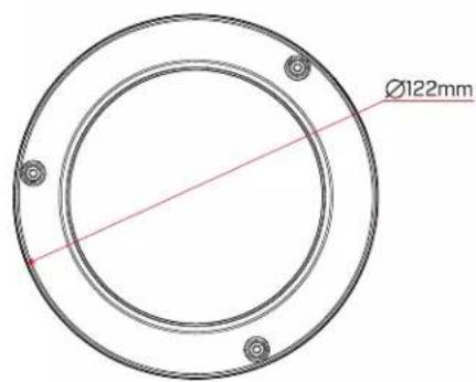
© 2017, Lorex Corporation
natural_image
Front view of a LOREX security camera with a central lens (no visible text or symbols beyond branding)flowchart
graph LR
    A["Camera"] --> B["RS-485"]
    B --> C["BNC"]
    C --> D["12V DC"]
    D --> E["2"]
    E --> F["Extension Cable (not included)"]
    F --> G["DVR (not included)"]
natural_image
Close-up of a white dome-shaped object with a black cable inserted, labeled with number 1 (no text or symbols on the object itself)- Ranura para cables
4.3.1 Soporte de pared
natural_image
Line drawing of a handheld device with a circular base and cable routing (no text or symbols)natural_image
Technical line drawing of a device casing with labeled components (no text or symbols)natural_image
Technical line drawing of a mechanical device connected to a wall-mounted panel (no text or symbols)
ATENCIÓN
natural_image
Technical line drawing of a mechanical device with a labeled component (1), no text or symbols present.natural_image
Technical line drawing of a surveillance camera mounted on a wall-mounted device (no text or symbols present)natural_image
Technical line drawing of a mechanical device mounted on a wall, showing no text or symbols.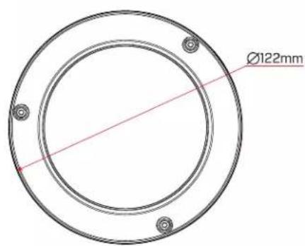
© 2017, Lorex Corporation