
L114V251 - Surveillance Camera Lorex - Free user manual and instructions
Find the device manual for free L114V251 Lorex in PDF.

| Product Type | Digital Video Recorder (DVR) for surveillance cameras |
| Model | L114V251 (L114 Series) |
| Video Input | 4 x BNC (1Vp-p 75 ohms) |
| Video Output | 1 x BNC (Monitor Out), 1 x VGA |
| Audio Input | 1 x RCA line-in |
| Audio Output | 1 x RCA line-out |
| Compression Format | MJPEG |
| Recording Frame Rate | NTSC: 60 fps max; PAL: 50 fps max |
| Display Resolution | NTSC: 640x448; PAL: 640x544 |
| Hard Drive | 3.5" SATA, up to 1 TB |
| Backup Method | USB flash drive (front panel) |
| Power Supply | 12V DC / 4A (AC 100-240V 50/60Hz) |
| Dimensions (WxDxH) | 220 mm x 228 mm x 48 mm (8.66" x 8.99" x 1.89") |
| Weight | 1.5 kg / 3.31 lbs |
| Recording Modes | Time (Continuous), Motion, Manual |
| Motion Detection | Adjustable sensitivity (1-4) and alarm duration (5-30 sec) |
| Audio Recording | Mono, line-in |
| Password Protection | 6-character password (default: 111111) |
| Remote Control | IR remote with CR2025 battery |
| Firmware Upgrade | Via USB flash drive |
| Safety Certifications | FCC Class B, UL/CSA |
Frequently Asked Questions - L114V251 Lorex
User questions about L114V251 Lorex
0 question about this device. Answer the ones you know or ask your own.
Ask a new question about this device
Download the instructions for your Surveillance Camera in PDF format for free! Find your manual L114V251 - Lorex and take your electronic device back in hand. On this page are published all the documents necessary for the use of your device. L114V251 by Lorex.
USER MANUAL L114V251 Lorex
natural_image
Black LOREX device front panel with ports and control buttons (no readable text beyond branding)MODEL:
L114V SERIES

LOREX®
www.lorexcctv.com
Thank you for purchasing the L114 Digital Video Surveillance Recorder. Lorex is committed to providing our customers with a high quality, reliable security product.
The L114 series offers excellent performance at a value price. This small form (9x12x2") surveillance DVR provides real time recording in quad mode and single channel, as well as audio recording and motion detection. The L114 also has a remote control and password protection.
To learn more about the DVR, and to learn about our complete range of accessory products, please visit our website at:
www.lorexcctv.com

CAUTION
RISK OF ELECTRIC SHOCK DO NOT OPEN

CAUTION: TO REDUCE THE RICK OF ELECTRIC SHOCK DO NOT REMOVE COVER. NO USER SERVICABLE PARTS INSIDE. REFER SERVICING TO QUALIFIED SERVICE PERSONNEL.

The lightning flash with arrowhead symbol, within an equilateral triangle, is intended to alert the user to the presence of uninsulated "dangerous voltage" within the products ' enclosure that may be of sufficient magnitude to constitute a risk of electric shock

The exclamation point within an equilateral triangle is intended to alert the user to the presence of important operating and maintenance (servicing) instructions in the literature accompanying the appliance.
WARNING: TO PREVENT FIRE OR SHOCK HAZARD, DO NOT EXPOSE THIS UNIT TO RAIN OR MOISTURE.
CAUTION: TO PREVENT ELECTRIC SHOCK, MATCH WIDE BLADE OF THE PLUG TO THE WIDE SLOT AND FULLY INSERT.
Important Safeguards
In addition to the careful attention devoted to quality standards in the manufacture process of your video product, safety is a major factor in the design of every instrument. However, safety is your responsibility too. This sheet lists important information that will help to assure your enjoyment and proper use of the video product and accessory equipment. Please read them carefully before operating and using your video product.
Installation
- Read and Follow Instructions - All the safety and operating instructions should be read before the video product is operated. Follow all operating instructions.
- Retain Instructions - The safety and operating instructions should be retained for future reference.
- Heed Warnings - Comply with all warnings on the video product and in the operating instructions.
- Polarization - Do not defeat the safety purpose of the polarized or grounding-type plug.
A polarized plug has two blades with one wider than the other.
A grounding type plug has two blades and a third grounding prong.
The wide blade or the third prong are provided for your safety.

If the provided plug does not fit into your outlet, consult an electrician for replacement of the obsolete outlet
- .Power Sources - This video product should be operated only from the type of power source indicated on the marking label. If you are not sure of the type of power supply to your location, consult your video dealer or local power company. For video products intended to operate from battery power, or other sources, refer to the operating instructions.
- Overloading - Do not overload wall outlets of extension cords as this can result in the risk of fire or electric shock. Overloaded AC outlets, extension cords, frayed power cords, damaged or cracked wire insulation, and broken plugs are dangerous. They may result in a shock or fire hazard. Periodically examine the cord, and if its appearance indicates damage or deteriorated insulation, have it replaced by your service technician.
-
Power-Cord Protection - Power supply cords should be routed so that they are not likely to be walked on or pinched by items placed upon or against them, paying particular attention to cords at plugs, convenience receptacles, and the point where they exit from the video product.
-
Ventilation - Slots and openings in the case are provided for ventilation to ensure reliable operation of the video product and to protect it from overheating. These openings must not be blocked or covered. The openings should never be blocked by placing the video equipment on a bed, sofa, rug, or other similar surface. This video product should never be placed near or over a radiator or heat register. This video product should not be placed in a built-in installation such as a bookcase or rack unless proper ventilation is provided or the video product manufacturer's instructions have been followed.
- Attachments - Do not use attachments unless recommended by the video product manufacturer as they may cause a hazard.
- Water and Moisture - Do not use this video product near water. For example, near a bath tub, wash bowl, kitchen sink or laundry tub, in a wet basement, near a swimming pool and the like.
Caution: Maintain electrical safety. Powerline operated equipment or accessories connected to this unit should bear the UL listing mark of CSA certification mark on the accessory itself and should not be modified so as to defeat the safety features. This will help avoid any potential hazard from electrical shock or fire. If in doubt, contact qualified service personnel.
- Accessories - Do not place this video equipment on an unstable cart, stand, tripod, or table. The video
equipment may fall, causing serious damage to the video product. Use this video product only with a cart, stand, tripod, bracket, or table recommended by the manufacturer or sold with the video product. Any mounting of the product should follow the manufacturer's instructions and

use a mounting accessory recommended by the manufacturer.
Service
- Servicing - Do not attempt to service this video equipment yourself as opening or removing covers may expose you to dangerous voltage or other hazards. Refer all servicing to qualified service personnel.
- Conditions Requiring Service - Unplug this video product from the wall outlet and refer servicing to qualified service personnel under the following conditions.
A. When the power supply cord or plug is damaged.
B. If liquid has been spilled or objects have fallen into the video product.
C. If the video product has been exposed to rain or water.
D. If the video product does not operate normally by following the operating instructions. Adjust only those controls that are covered by the operating instructions. Improper adjustment of other controls may result in damage and will often require extensive work by a qualified technician to restore the video product to its normal operation.
E. If the video product has been dropped or the cabinet has been damaged.
F. When the video product exhibits a distinct change in performance. This indicates a need for service.
- Replacement Parts - When replacement parts are required, have the service technician verify that the replacements used have the same safety characteristics as the original parts. Use of replacements specified by the video product manufacturer can prevent fire, electric shock or other hazards.
- Safety Check - Upon completion of any service or repairs to this video product, ask the service technician to perform safety checks recommended by the manufacturer to determine that the video product is in safe operating condition.
- Wall or Ceiling Mounting - The cameras provided with this system should be mounted to a wall or ceiling only as instructed in this guide, using the provided mounting brackets.
- Heat - The product should be situated away from heat sources such as radiators, heat registers, stoves, or other products (including amplifiers) that produce heat.
Use
- Cleaning - Unplug the video product from the wall outlet before cleaning. Do not use liquid cleaners or aerosol cleaners. Use a damp cloth for cleaning.
- Product and Cart Combination - Video and cart combination should be moved with care. Quick stops, excessive force, and uneven surfaces may cause the video product and car combination to overturn.
- Object and Liquid Entry - Never push objects for any kind into this video product through openings as they may touch dangerous voltage points or "short-out" parts that could result in a fire or electric shock. Never spill liquid of any kind on the video product.
- Lightning - For added protection for this video product during a lightning storm, or when it is left unattended and unused for long periods of time, unplug it from the wall outlet and disconnect the antenna or cable system. This will prevent damage to the video product due to lightning and power line surges.
General Precautions
- All warnings and instructions of this manual should be followed.
- Remove the plug from the outlet before cleaning. Do not use liquid aerosol detergents. Use a water dampened cloth for cleaning.
- Do not use this unit in humid or wet places.
- Keep enough space around the unit for ventilation. Slots and openings in the storage cabinet should not be blocked.
- During lightning storms, or when the unit is not used for a long time, disconnect the power supply, antenna, and cables to protect the unit from electrical surge.
FCC CLASS B NOTICE
Note
This equipment has been tested and found to comply with the limits for a Class B digital device, pursuant to Part 15 of the FCC Rules. These limits are designed to provide reasonable protection against harmful interference in a residential installation. This equipment generates, uses, and can radiate radio frequency energy and, if not in-stalled and used in accordance with the instruction, may cause harmful interference to radio communications.
However, there is no guarantee that interference will not occur in a particular installation. If this equipment does cause harmful interference to radio or television reception (which can be determined by turning the equipment on and off), the user is encouraged to try to correct the interference by one or more of the following measures:
- Reorient or relocate the receiving antenna
- Increase the separation between the equipment and receiver
- Connect the equipment into an outlet on a circuit different from that to which the receiver is connected
- Consult the dealer or an experienced radio or television technician for assistance
This equipment has been certified and found to comply with the limits regulated by FCC, EMC, and LVD. Therefore, it is designated to provide reasonable protection against interference and will not cause interference with other appliance usage.
However, it is imperative that the user follows this manuals guideline to avoid improper usage which may result in damage to the unit, electrical shock and fire hazard injury
In order to improve the feature functions and quality of this product, the specifications are subject to change without notice from time to time.

LOREX®
www.lorexcctv.com
Features
natural_image
Black LOREX internal storage unit with ports and control buttons (no readable text beyond branding)• Simultaneous Recording and Playback
- Up to 60 fps recording speed
- Backup to USB flash drive
- Adjustable screen position
• Quad and single channel recording
• NTSC / PAL
- MJPEG video compression
- Motion Detection with Adjustable Time Duration
- Date / Time search
• Power Recovery and Auto-Restore Record Mode
- Audio Recording
Table of Contents
Getting Started 1
Basic Setup 2
Connect the Cameras 2
Connect the Monitor 2
Connect the Power Adaptor 2
Front Panel 3
Rear Panel 4
Remote Control 5
Menu Navigation Tips & Tricks 5
Installing Cameras 6
Installation Warning 6
Assembling the Camera Stand 6
Connecting BNC Cameras 7
Camera Connections 7
Starting the System 8
On-Screen Display 9
Display Modes 9
Auto Sequence Mode 10
Logging in to the System 11
Entering Your Password 11
Setting the Date and Time 12
Recording 13
Motion Recording 13
Manual Recording 13
Recording Audio 13
Playback 14
Searching for Recorded Video 16
Time Search 16
Event List 17
Using the Setup Menu 19
Camera 20
Covert Channel Display 20
Record 21
Motion Detection 22
Motion Area 22
Screen 23
Audio 23
System 24
Hard Disk Setup 24
Password Change 25
Time Set 25
Event List 25
Loss Alarm 25
F/W Upgrade 25
Search 26
Exit 26
Load Setup Default 26
USB Backup 27
Playback 27
Search 27
Event List (System Menu) 27
Using USB Backup 27
System Requirements 28
Using Lorex Client 29
Launching Lorex Client 29
Playing Saved Video Files 30
Playback Options 30
Sub-Menu 31
Capture 32
Exporting to AVI 33
Options 34
Appendix 1: System Specifications ....35
Appendix 2: Full Connectivity Diagram 36
Appendix 3: Using Listen-in Audio 37
Appendix 4: Replacing the Hard Drive ....38
Removing the Hard Drive 38
Replacing the Hard Drive 39
Formatting the Hard Drive 40
Appendix 5: Compression Codecs .... 41
Troubleshooting 42
Getting Started
The system comes with the following components:

natural_image
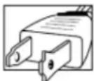
Black LOREX device with ports and indicator lights (no visible text or symbols on body)1 X DVR
natural_image
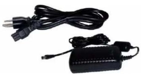
Electric guitar charger with black cable and power plug, no visible text or symbols1 X POWER ADAPTOR
1 X POWER CABLE

natural_image
Black remote control device with multiple function buttons (no visible text or symbols)1 X REMOTE CONTROL
INSTRUCTION MANUAL, QUICK START GUIDE, AND SOFTWARE CD
HARD DRIVE SIZE, NUMBER OF CHANNELS, AND CAMERA CONFIGURATION MAY VARY BY MODEL. PLEASE REFER TO YOUR PACKAGE FOR SPECIFIC CONTENT DETAILS. CHECK YOUR PACKAGE TO CONFIRM THAT YOU HAVE RECEIVED THE COMPLETE SYSTEM, INCLUDING ALL COMPONENTS SHOWN ABOVE.
Basic Setup
1. Connect the Cameras
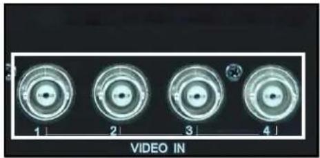
a. Connect up to four BNC cameras to the BNC (female) ports on the rear panel of the system.
2. Connect the Monitor
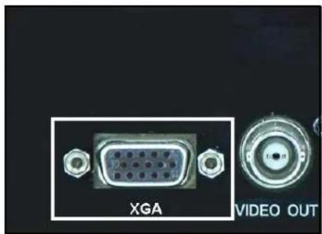
a. Connect the VGA cable from your monitor to the VGA port on the rear panel of the system.
3. Connect the Power Adaptor
a. Connect the power cable to the power adaptor.
b. Connect the power cable to the DC12V port on the rear panel of the system.
c. Connect the power adaptor to a wall outlet.
Optional
You can connect line-in audio (RCA) from an audio capable camera or microphone (not included). Use the audio-out port (RCA) to connect speakers (not included).
natural_image
Four circular video camera lens images labeled 1 to 4, with a small inset showing a magnified view (no text or symbols on the lenses themselves)Figure 1.0 Connect up to four BNC cameras
natural_image
Close-up of a VGA connector with hexagonal pins, labeled 'XGA' and 'VIDEO OUT' (no additional text or symbols)Figure 1.1 Connect a VGA monitor
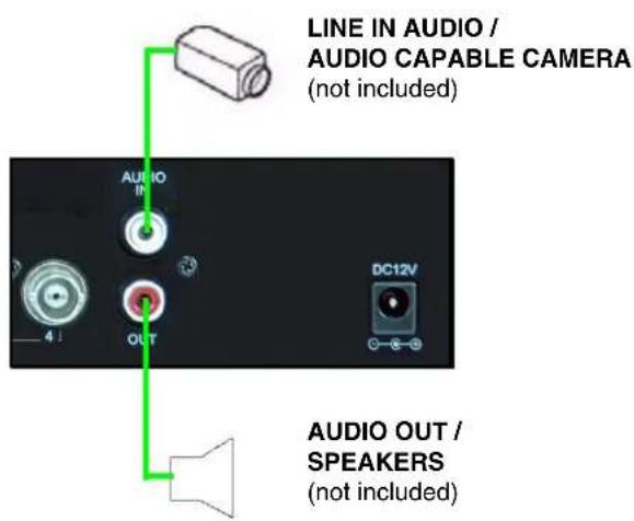
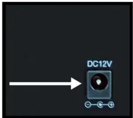
Figure 1.2 Connect the power cable
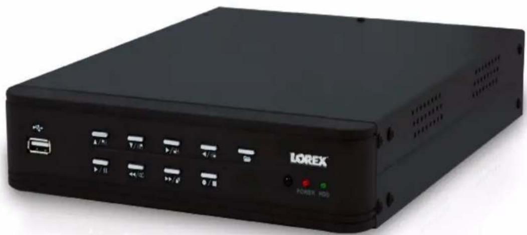
Front Panel
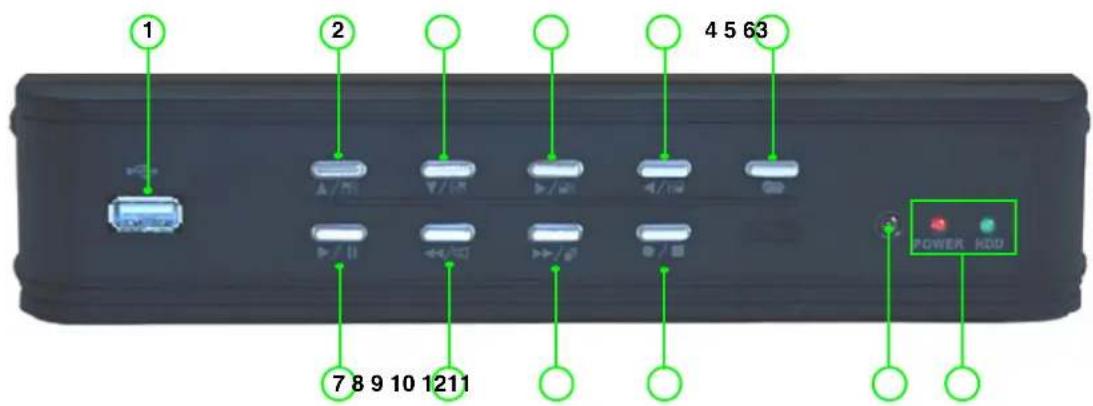
- USB 2.0 port: Connect a USB flash drive for backup.
- Up / CH 1: In menus, move cursor up; during live viewing, view channel 1 in full-screen.
- Down / CH 2: In menus, move cursor down; during live viewing, view channel 2 in full-screen.
- Right / CH 3: In menus, move cursor right; during live viewing, view channel 3 in full-screen.
- Left/ CH 4: In menus, move cursor left; during live viewing, view channel 4 in full-screen.
- Menu: Press to open system Menu; closes/exits options/menus.
- Play/Pause: During live viewing, press to open the Event List and select a recorded event; during playback, press to play/pause video.
- Rew/Mute: During playback, press to increase reverse playback speed (2X, 4X, 8X); in Live Mode, press to Mute/Unmute audio; in menus, press to enter/confirm selections.
- FF/Sequence: During playback, press to increase forward playback speed (2X, 4X, 8X); during live viewing, press to start/stop Auto-Sequence mode (system displays each channel in full-screen in sequence).
- Record/Stop: During playback, press to stop playback; during live viewing, press to start/stop manual recording (recording Schedule must be disabled).
- IR Receiver: Receives infrared signal from the remote control.
- Power / HDD Indicators: LED indicator for system power: when system is powered on, LED is red; LED indicator for internal hard disk: when in continuous recording mode, LED pulses green.
Rear Panel
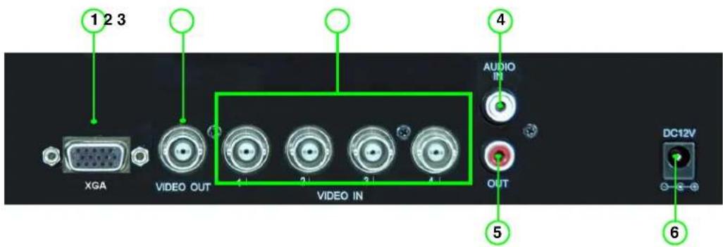
- XGA: Port to connect a VGA (VGA or XVGA output) monitor (not included).
- Video Out: BNC (female) port to connect the system to a DVR or observation system.
- Video In: BNC (female) inputs for cameras 1\~4.
- Audio In: RCA (female) port for audio recording (audio capable cameras or microphone).
- Audio Out: RCA (female) port to connect the system to external speakers, a DVR, or an observation system
- DC 12V: Power port for the included power adaptor.
Remote Control
The remote control is the primary input method for navigating the user interface of the system.
- CH 1\~4: During live viewing, press to view cameras 1\~4 in single channel full-screen; press 4 to return to quad split-screen; during USB Backup, 1=Start Time, 2=End Time, 3=N/A, 4=Start backup.
- ▲: Press to move cursor UP when navigating menus or while in Search mode.
- ▼: Press to move cursor DOWN when navigating menus or while in Search mode.
- ◀/+: During playback, press to increase reverse playback speed (2X, 4X, 8X); press to mute/unmute volume to a connect audio output device; in the Event List, press to switch pages.
- ▶/-: During playback, press to increase forward playback speed (2X, 4X, 8X); in the Event List, press to switch pages.
- ●/■: Start/stop manual recording—recording schedule must be disabled.
- MENU: Press to open system menu; closes/exits options/menus; during playback, press to open USB Backup menu.
- ENTER: Confirm menu selections; during playback of saved video.
- ▶ / || : During playback, press to play/pause video; during live viewing, press to open the Event List; in the Event List, press to playback selected file.
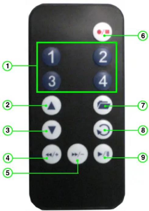
Figure 3.0 Remote Control
Menu Navigation Tips & Tricks
When navigating the system menus with the remote control, the following buttons are most commonly used on the remote control:
• /! Move cursor UP
• /: Move cursor DOWN
• / : Move cursor RIGHT
• /4 Move cursor LEFT
• : Confirm selection
• : Close/exit options/menus.
ATTENTION: This manual refers to basic navigation (up, down, left, right) as ▲▼◀▶. You can use buttons 1\~4 and the ▲▼◀▶ buttons for basic navigation.
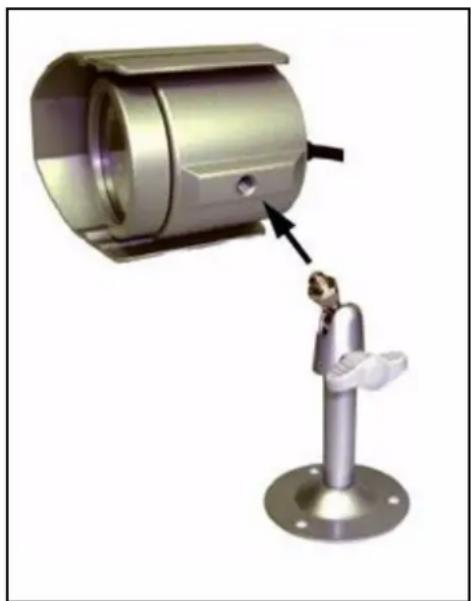
Installing Cameras
Before you install the camera, carefully plan where and how it will be positioned, and where you will route the cable that connects the camera to the DVR or observation system.
Installation Warning
- Select a location for the camera that provides a clear view of the area you want to monitor, which is free from dust, and is not in line-of-sight to a strong light source or direct sunlight.
- Plan the cables' route so that it is not close to power or telephone lines, transformers, microwave ovens or other electrical equipment that could interfere with the DVR.
- Select a location for the camera that has an ambient temperature between 14^ 113^ (-10^ 45^) .
- If you plan to install the camera in a location that has conditions not recommended in this manual, consult with a professional installer and consider use of a separate camera cover or housing.
- Before starting permanent installation, have another person hold the camera for you while you verify its performance by observing the image on a monitor.
Assembling the Camera Stand
To assemble the camera stand:
- Attach the pedestal to the ceiling, wall, or other surface by the base using the provided screws.
- Attach the camera to the pedestal. Adjust the angle of the camera, and tighten the thumbscrew to set the position.
Note: You can attach the camera to the stand using the screw point on the top or the bottom of the camera (to maintain proper camera alignment). This prevents the image from becoming inverted.
natural_image
3D rendering of a mechanical sensor or camera module with a mounted probe and a close-up view showing the component (no text or symbols visible)Figure 4.0 Attach camera to base
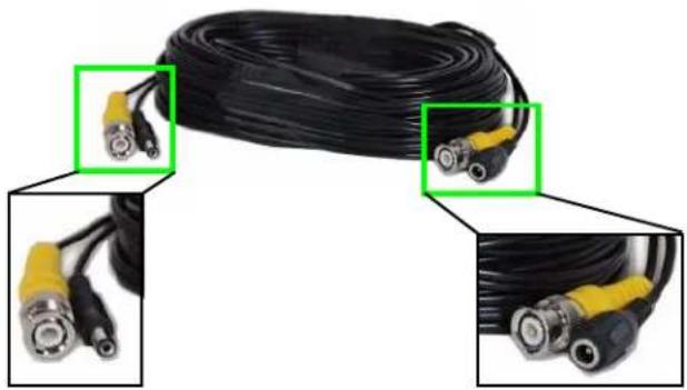
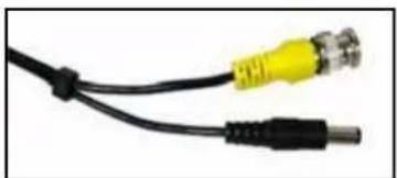
Connecting BNC Cameras
Use a BNC/Power extension cable (not included) to connect your BNC cameras to a monitor, DVR, or observation system and power source.
To connect the extension cable:
-
Connect the extension cable to the camera:
-
Connect the BNC cable to the camera.
-
Connect the power cable (male) to the camera.
-
Connect the extension cable to the DVR/monitor/observation system:
-
Connect the BNC cable to BNC port (female) on the DVR.
- Connect the power cable to a power adaptor.
natural_image
Close-up of a black cable with two connected BNP cables, shown in three views (no text or symbols visible)Figure 5.0 Male and female ends of BNC/Power extension cable
ATTENTION - The ends of the extension cable are NOT THE SAME: one end has a male connector and the other end has a female connector. Before permanently running the cable, make sure you have oriented the extension cable correctly between the camera and the DVR, monitor, or observation system.
natural_image
Close-up of a black cable with two metallic connectors (no text or symbols visible)Power cable—male: Connect the male power cable to the camera.
natural_image
Close-up of a black cable with two yellow connectors (no text or symbols visible)Power cable—female: Connect the female power cable to the power adaptor.
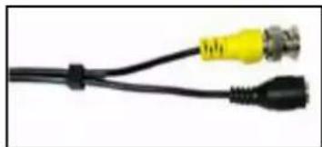
Camera Connections
flowchart
graph TD
    A["DVR"] -->|Video IN| B["Power Socket"]
    B --> C["BNC"]
    C --> D["Adaptor"]
    D --> E["Wall Socket"]
    E --> F["Camera"]
    style A fill:#f9f,stroke:#333
    style F fill:#ccf,stroke:#333
Figure 5.1 Full connectivity diagram
Starting the System
To power the system On/Off:
- Connect the power cable to the DC 12V port on the rear panel of the system
Note: Make sure all cameras and cables are properly connected prior to powering on the system.
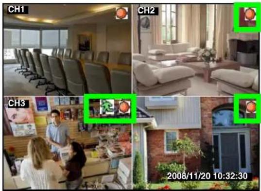
At startup, the system performs a basic system check and runs an initial loading sequence. After a few moments, the system loads a live Quad split-screen display view—Live Viewing: you can also view in full-screen single channel. See “Display Modes” on page 9.
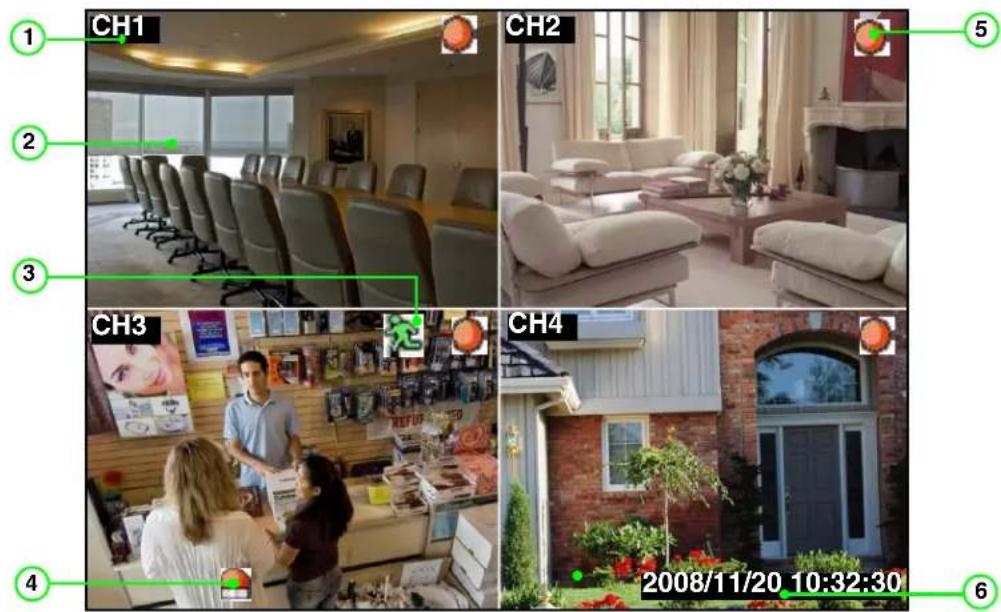
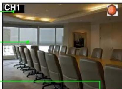
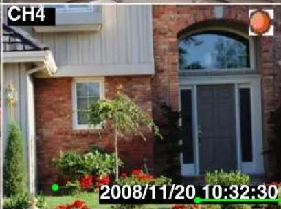
Camera Title, Status Icons, and Date / Time bar appear on the On-Screen Display.
natural_image
Interior view of a modern conference room with rows of chairs and large windows (no visible text or symbols)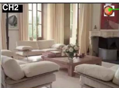
natural_image
Interior living room scene with white sofas, a coffee table, and large windows (no visible text or symbols)
natural_image
Exterior view of a brick house with a large arched doorway and surrounding greenery (no signage)Figure 6.0 Live viewing with on-screen display
- Camera Title: CH1\~4 appears in the top-left corner of each channel.
- Main Display: Displays both full-screen single channel and Quad split-screen.
- Status Icons: Status icons for Motion recording and Video Loss.
- Motion Alarm Icon: Icon for triggered motion alarm.
- Recording Icon: Shown during active recording (manual and scheduled recording).
- Date / Time: Year/month/day and hour/minute/second appear in a black bar in the bottom-left corner of the main display screen.
On-Screen Display
The following makeup the on-screen display of the system:
- Recording: Indicates active recording on each channel (manual and scheduled recording).
• Motion: Indicates motion recording or motion detected on active channel.
• Motion Alarm: Indicates motion has been detected on active channel.
Note: Sensitivity and Alarm Duration must be enabled for the selected channel.
• Video Loss: Indicates that a camera is not connected or has been disconnected.
- Date / Time bar: The date appears as yyyy/mm/dd; the time appears as hh/mm/ss.
Note: You cannot change the date and time format.
2008/11/20 10:32:30
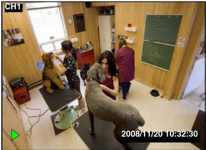
Display Modes
The system can display channels in full-screen single channel and quad split-screen. It also features an Auto Sequence Mode, where all four channels are displayed in sequence in full-screen.
Note: By default, the system loads the quad split-screen at startup.
To change display modes:
-
Press buttons 1 2 3 4 on the remote control to view each respective channel in full-screen.
-
Press the 4 button to return to Quad split-screen.

natural_image
Interior of a cozy room with two dogs, one seated on a bench and the other standing near a chalkboard (no visible text or symbols)Single Channel Full-Screen
natural_image
Four-panel collage showing interior scenes: a meeting room with chairs, a living room with sofa, a retail store interior, and a brick house at night (no visible text or symbols)Quad Split-Screen
Figure 6.1 Display modes
Auto Sequence Mode
In Auto Sequence Mode, the system automatically switches between full-screen channels 1\~4 in sequence.
natural_image
Interior view of a modern living room with staircase and lounge (no visible text or symbols)
natural_image
Two black curved arrows forming a circular loop on white background (no text or symbols)

Figure 6.2 Auto Sequence Mode
To enable/disable Auto Sequence Mode:
- Press the button on the front panel. "AUTO" appears in the bottom-right corner of the main display screen; the system begins displaying full-screen channels in sequence.
Note: Auto Sequence can be started in both full-screen single channel and quad split-screen modes.
- Press the button again to stop Auto Sequence Mode. By default, the system returns to quad split-screen mode.
You can customize the dwell time for Auto Sequence mode. For more details, see "Screen" on page 23.
Logging in to the System
You must login to the system with a 6-character password every time you access the system Setup Menu.
ATTENTION: The default system password is 111111
Entering Your Password
If your press the screen will appear. button on the front panel or on the remote control, the password
To enter your password:
- Press the following buttons on the remote control to move the cursor and input selections:
- /! Move cursor UP
• / 4 Move cursor LEFT
• /: Move cursor DOWN
- Confirm selection
• /3 Move cursor RIGHT
-
Select Shift and press 📋 to change to uppercase characters and symbols.
-
Select + and press 🔍 to delete/backspace.
-
When finished, select Enter and press .
For more details on changing your password, see "Password Change" on page 25.
Setting the Date and Time
It is highly recommended to immediately set the date and time when first setting up your system.
To set the date and time:
- Click 📄 to open the Setup Menu. Login with your system password (by default, 111111).
- Select System and press .
- Select Time Set and press Ⓞ . The Time Set menu appears.
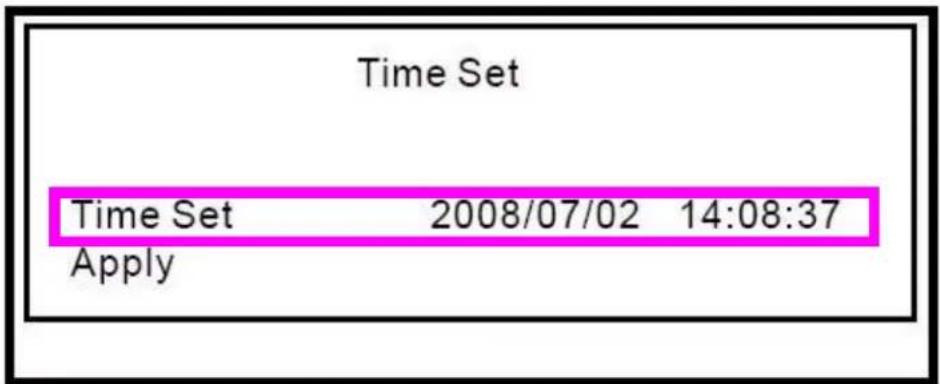
Figure 6.3 Time Set screen
- Under Time Set, press ◀▶ to select the date and time (yyyy/mm/dd and hh/mm/ss) and press ▲▼ to change values.
- Press 📄 and then select Apply and press ⏻ . The new time is saved.
- Press repeatedly to exit all menus.
Recording
By default, the system is set to immediately record video from connected cameras in continuous Time Record Mode.
The system automatically records and saves events in 4-hour blocks. Active recording is indicated by the red Record Icon in the top-right corner of each channel.
natural_image
Four-panel collage showing interior scenes: office with chairs, living room with sofa, meeting room with staff, and brick house at night (no visible text or symbols)Figure 7.0 Recording on all four channels
Motion Recording
You can configure the system to only record when motion is detected on selected cameras. Motion Recording is indicated by the green Motion Icon in the top-right corner of the channel. You can configure both Time Recording and Motion Recording in the Record Schedule in the Setup Menu. See "Record" on page 21.
Manual Recording
Press ⏻ on the remote control or press 📄 on the front panel to start/stop manual recording on all four channels.
Note: "No Recording" must be selected in the Record Schedule in order to use manual recording. See "Record" on page 21.
Recording Audio
The system can record one audio channels. You must have audio enabled cameras or microphones connected to the system in order to use this function.
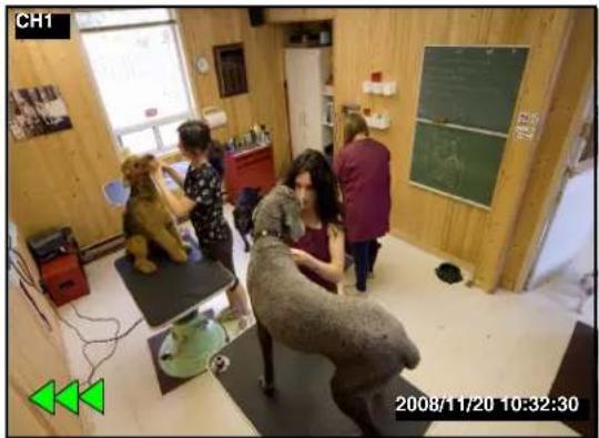
Playback
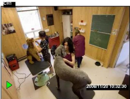
View recorded video on the system through playback mode.
natural_image
Interior of a dog-themed room with people interacting near a dog sculpture, no visible text or symbols on the main subjects.Figure 8.0 Playback display view
To begin playback:
- Press ▶/Ⅱ. The Event List opens. For more details, see "Event List" on page 17.
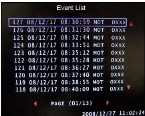
Figure 8.1 Event List
- Press ▲▼ to select a record event from the list (press ◀▶ to turn pages) and press ⬇/Ⅱ. Playback begins for the selected event.
Note: Please allow a few seconds for the event file to load.
-
During playback, you have access to the following:
-
Press to pause playback; press again to resume playback
- Click to increase reverse playback speed (2X, 4X, 8X).
- Click to increase forward playback speed (2X, 4X, 8X).
natural_image
Interior scene of a dog-themed room with people and furniture, no visible text or symbolsFigure 8.2 Icons for 8X reverse playback
4. Press

to stop playback.
During playback, you can select start/stop times for a selected clip and backup the data to a USB flash drive (not included). For more details on USB Backup, see "USB Backup" on page 27.
Searching for Recorded Video
You can search for recorded video on the system using Time Search or the Event List.
Time Search
Use Time Search to manually select a time for the system to search for record video.
To use Time Search:
- Press ☐ to open the Setup Menu. Login with your system password (by default, 111111).
- From the Setup Menu, select Search and press 📋. The Time Search menu opens.
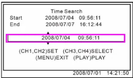
Figure 9.0 Time Search menu
-
Press ◀▶ to select the date and time (yyyy/mm/dd and hh/mm/ss) and press ▲▼ to change values.
-
Press ▶/Ⅱ. Playback begins for the selected time.
Note: Please allow a few moments for the system to search for the requested data.
-
During playback, you have access to the following:
-
Press to pause playback; press again to resume playback
- Click to increase reverse playback speed (2X, 4X, 8X).
-
Click to increase forward playback speed (2X, 4X, 8X)
-
Press ☐ to stop playback.
Event List
You can also search for recorded video data by using the Event List.
Note: The Event List contains events which have occurred over the last 4 hours.
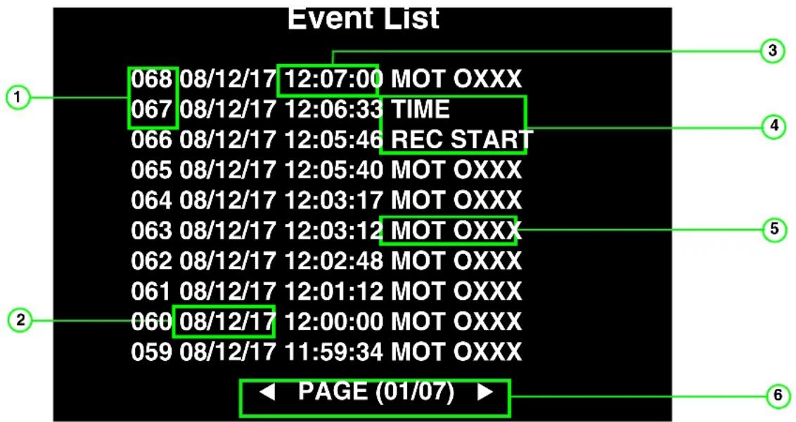
Figure 9.1 Event List
- Event Number: The system tags each event with a number; the highest number indicates the most recent event.
- Date: The date the event occurred (yy/mm/dd).
- Time: The time the event occurred (hh/mm/ss).
-
Message: System messages for particular instances:
-
REC START: Recording started on the system
- REC STOP: Recording stopped on the system.
- TIME: time changed on system's internal clock (the system saves a 4-hour block for each recorded event).
-
POWER ON: The system has been powered on.
-
MOT Status: Motion status for channels 1\~4. 0 = motion detection enabled; X = motion detection disabled.
-
Page: There are ten events for page; press ◀▶ to turn pages in the Event List.
To use the Event List:
- Press

. The Event List opens.
- Press ▲▼ to select a record event from the list (press ◀▶ to turn pages) and press 🧑/∥. Playback begins for the selected event.
Note: Please allow a few seconds for the event file to load.
-
During playback, you have access to the following:
-
Press to pause playback; press again to resume playback
- Click to increase reverse playback speed (2X, 4X, 8X).
- Click to increase forward playback speed (2X, 4X, 8X).
natural_image
Interior of a small room with two people seated on tables, one holding a teddy bear, and another observing; no visible text or symbols.Figure 9.2 Playback from Event List
- Press

to stop playback.
During playback (from Time Search or from the Event List), you can select start/stop times for a selected clip and backup the data to a USB flash drive (not included). For more details on USB Backup, see "USB Backup" on page 27.
Using the Setup Menu
The Setup menu allows you to configure various settings on the system, including date/time, camera settings, and motion detection.
To open the Setup menu:
- Press 📋. You must login with your system password (by default, 111111).
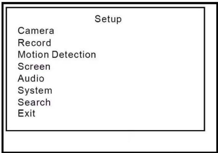
Figure 10.0 Setup Menu
The Setup Menu contains the following options:
- Camera
- Record
- Motion Detection
- Screen
- Audio
- System
- Search
- Exit

natural_image
Simple line drawing of a light bulb with radiating lines (no text or symbols)TIP!
When navigating menus:
- Press ▲▼ to select options.
- Press or ◀ to confirm
selections.
Camera
Configure settings for each camera and enable/disable display on the main display screen (covert display).
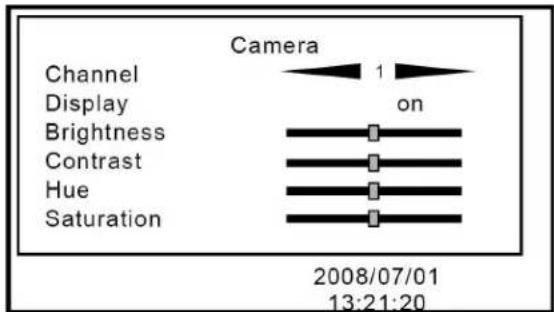
Figure 11.0 Camera menu
To configure camera settings:
- From the Setup Menu, select Camera and
press 📋. The Camera menu opens.
-
Under Channel, press ◀▶ to select camera 1, 2, 3, or 4.
-
Select the following options and press ◀▶ to increase/decrease the sliders:
-
Brightness
- Contrast
• Hue -
Saturation
-
Press until the Exit menu appears.
Select Save & Exit and press 📄 to save your settings.
Covert Channel Display
You can turn off a channel from the main display screen from the system Main Menu. Use this function as a covert camera display.
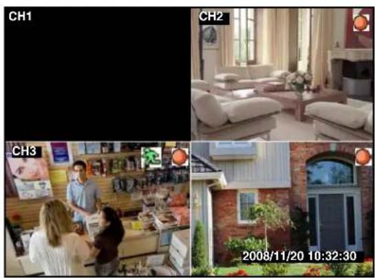
Figure 11.1 Diabled/covert camera display
To enable/disable covert camera display:
-
From the Camera menu, select Channel and press ◀▶ to channel 1\~4.
-
Select Display and press ◀▶ to select On/Off.
-
Press until the Exit menu appears.
Select Save & Exit and press 🔍 to save your settings. The disabled channel will appear black.

TIP!
If your monitor is in a public viewing area, use the disable display feature for covert recording. The system will continue to record from the connected camera, but the display on the monitor gives the appearance that a camera is not connected
Record
Set record speed, quality, record schedule and recording duration for triggered events.
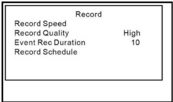
Figure 12.0 Record Menu
To configure record settings:
- From the Setup Menu, select Record and
press 📊 . The Record menu opens.
- Select the following options and press
◀▶ to configure settings:
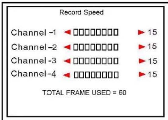
- Record Speed:
Select channels 1\~4 and press ◀ to set the frames per second (FPS) for each channel. NTSC: by default, 15 fps; max. 60 fps. PAL: by default, 12 fps, max. 50 fps.
bar
Record Speed | Channel | Record Speed | |---|---| | Channel -1 | ▶□□□□□□□ ▶ 15 | | Channel -2 | ▶□□□□□□□ ▶ 15 | | Channel -3 | ▶□□□□□□□ ▶ 15 | | Channel -4 | ▶□□□□□□□ ▶ 15 | TOTAL FRAME USED = 60Figure 12.1 Record Speed menu
- Record Quality:
Set as Normal, High, or Highest.
• Event Rec Duration:
Event Record Duration is the length of time the system will record when motion is detected on a selected camera. Set from 5, 10, 15, 20, 25, or 30 seconds (by default, 10 seconds).
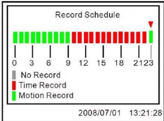
- Record Schedule:
Press ◀▶ to select each hour from 0\~23. Press ▲▼ to set the record method (Red=Time/Continuous Recording, Green=Motion Recording, Grey=No recording).
Note: In order to use Manual Recording, you must apply "No Recording" to a selected hour block in the record Schedule.
bar
| Time | Record Type | |------|-----------------| | 0 | No Record | | 3 | No Record | | 6 | No Record | | 9 | No Record | | 12 | Time Record | | 15 | Time Record | | 18 | Time Record | | 21 | Motion Record | | 23 | Motion Record |Figure 12.2 Record Schedule
- Press

until the Exit menu appears.
Select Save & Exit and press save your settings.

to
Motion Detection
Configure settings for motion sensitivity, motion grid, and the motion alarm for channels 1\~4.
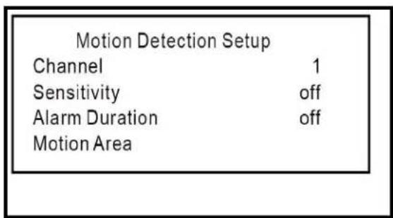
Figure 13.0 Motion Detection Setup menu
To apply motion detection:
- From the Setup Menu, select Motion
Detection and press 📄. The Motion Detection Setup menu opens.
- Select Channel, and press ◀▶ to select channels 1\~4.
- Select Sensitivity and press ◀▶ to select 1\~4, or Off (1=lowest sensitivity, 4=highest sensitivity).
- Select Alarm Duration and press ◀▶ to select 5, 10, 15, 20, 25, 30, CONT (continuous), or Off.
Note: Alarm Duration enables a buzzer to accompany motion detection. Set the time (in seconds) for the buzzer to sound when motion is detected on a selected camera.
- Press until the Exit menu appears.
Select Save & Exit and press 📋 to save your settings.

Note: Sensitivity and Alarm Duration must be enabled in order to see the Alarm icon when motion is detected on a selected channel.
Motion Area
Motion Area allows you set the specific area of the channel for motion detection. This can be useful in both high traffic and static areas.
ATTENTION: The Motion Area can only be set using the buttons on the front panel.
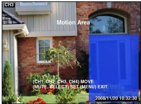
Figure 13.1 Motion Area
To configure the motion area:
- From the Setup Menu, select Motion
Detection and press 📄. The Motion Detection Setup menu opens.
-
Select Motion Area and press
-
Press ▲▼◀▶ to move the cursor to a desired area. Press 4/10 to set the cursor.
-
Press ▲▼◀▶ to apply the blue motion
area. When finished, press to set.
- Press until the Exit menu appears.
Select Save & Exit and press to save your settings.
Screen
Use the Screen menu to set resolutions, turn the channel border on/off, adjust the main display position, and set the dwell time for Auto Sequence Mode..
| Screen | |
| Border | off |
| Video Adjustment | |
| Auto Switching | 05 |
| Resolution | 1024 x 768 |
Figure 14.0 Screen menu
To configure screen settings:
- From the Setup Menu, select Screen and
press 📊 . The Screen menu opens.
- Select Border and press ◀▶ to select On/Off. If On, a white border appears in Quad mode dividing the quadrants of the main display screen.
- Select Video Adjustment and press ◀▶. The menu disappears. Press ▲▼◀▶ to adjust the vertical and horizontal position of the main display.
- Select Auto Switching and press ◀▶ to set the dwell time for Auto Sequence mode from 1\~10 seconds or Off. The higher the time, the longer the single channel will remain on-screen during Auto Sequence mode.
- Select Resolution and press ◀▶ to set the display resolution at 640x480, 800x600, 1024x768 (default), or 1280x1024.
- Press until the Exit menu appears.
Select Save & Exit and press save your settings.

Audio
Use the Audio menu to enable/disable audio recording, change audio input/output volume, and enable/disable mute.
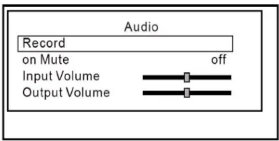
Figure 15.0 Audio menu
To configure audio settings:
- From the Setup Menu, select Audio and
press 📋. The Audio menu opens. - Select Record and press ◀▶ to turn audio recording On/Off.
Note: If audio recording is enabled, you must connect line-in audio (RCA) to the Audio-In port on the rear panel of the system. - Select Mute and press ◀▶ to Mute On/Off. If off, all audio on the system will be disabled (input and output).
- Select Input Volume and press ◀▶ to increase/decrease the slider.
- Select Output Volume and press ◀▶ to increase/decrease the slider.
- Press until the Exit menu appears.
Select Save & Exit and press save your settings.

to
System
Use the Sytem menu to configure the internal hard drive, change your password, set the date/time, view the event list, enable/disable the video loss alarm, and upgrade system firmware.
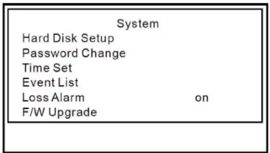
Figure 16.0 System menu
To configure system settings:
- From the Setup Menu, select System and press. The System menu opens.
Hard Disk Setup
The Hard Disk Setup menu displays the size of the internal hard drive (Disk 0) and amount of drive space currently consumed (in MB).
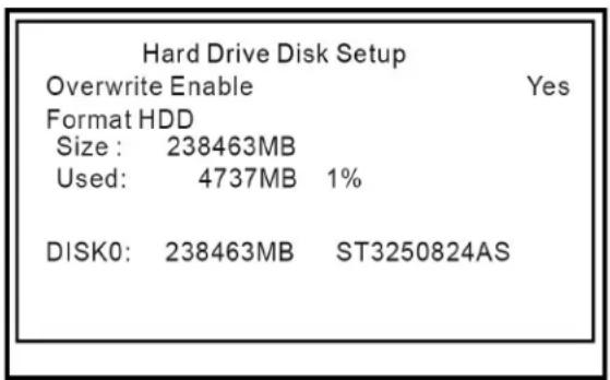
Figure 16.1 Hard Disk Setup menu
Use Hard Disk Setup to enable/disable disk overwrite.
Overwrite Enable
- From the Hard Disk Setup menu, select Overwrite Enable and press ◀ to select Yes or No.
Note: If Yes, the system will overwrite the oldest recorded video data on the hard drive once the hard drive is full (the system stores the last 4 hours of any recorded event). If No, the system will prompt you that the hard drive is full and will stop recording.
Format HDD
Use Hard Disk Setup to format the internal hard drive.
Note: You must stop recording before attempting to format the hard drive.
ATTENTION: Formatting erases all recorded video data on the hard drive. Formatting cannot be undone. System settings are not affected by formatting.
To format the hard drive:
- Select Format HDD and press ◀▶.
Note: If you have not already stopped recording, you will be prompted to press CH4(◀) to stop recording prior to formatting.
- Enter your 6-character system password. The system begins formatting the hard drive. This could take several moments depending on the size of your system's hard drive.
Once formatting is complete, the system will return to Live Mode.
Password Change
Use Hard Disk Setup to change your system password (by default, 111111).
![Password Change Current Password 1 2 3 4 5 6 7 8 9 0 - = + q w e r t y u l o p [ ] a s d f g h j k l ; Shift z x c v b n m , . / Enter](/content/2026/06/1184688/images/f2a00e44196e90c3fec035025b7b085dc8fabd04cf69eafeee5a011f26eaee5a.jpg)
Figure 16.2 Password Change screen
To change your system password:
- From the Hard Disk Setup menu, select Password Change and press ◀▶.
- Enter your current password.
Note: Enter your new 6-character password. Select Shift to view uppercase characters and symbols.
- Re-enter your new 6-character password to confirm. The password screen closes and returns you to the System menu.
- Press until the Exit menu appears.
Select Save & Exit and press 📋 to save your settings.
ATTENTION: You must save your settings from the Exit menu for your new password to take effect.
Time Set
You should always set the date and time when first starting up the system. For details on setting the time, see “Setting the Date and Time” on page 12.
Event List
You can access the Event List from the System menu. For more details on using the Event List, see "Event List" on page 17.
Loss Alarm
Enable/disable the buzzer when a camera is disconnected.
To enable/disable the loss alarm:
- From the System menu, select Loss Alarm and press ◀▶ to select On/Off.
Note: If On, a short buzzer will sound if a camera is disconnected; the loss icon will also appear in the top-right corner of the affected channel. If Off, the buzzer will not sound, but the loss icon will appear in the top-right corner of the affected channel.
F/W Upgrade
Firmware upgrades can provide improved functionality to your system. You can download these free upgrades from www.lorexcctv.com
Note: You must disable recording on the system prior to updating the firmware.
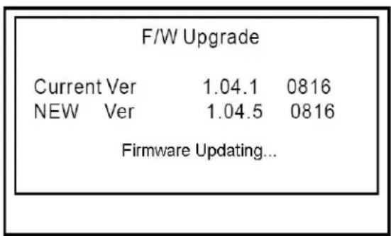
Figure 16.3 Firmware upgrade screen
To upgrade firmware:
-
Download the update from www.lorexcctv.com to your PC. The firmware carries the file extension, .FWI
-
Connect a USB flash drive to your PC. Copy the .FWI file to the connect USB flash drive.
- Connect the USB flash drive to the USB port on the front panel of the system
- Open the Setup menu. Login with your system password (by default 111111).
- From the Setup menu select System and press ◀▶.
Note: The current firmware version appears under F/W Update in the System menu.
- Select F/W Update and press ◀▶.
Note: If you have not already stopped recording, the system will prompt you to press 4 to stop recording.
- Press 📋 to start the firmware update. The screen closes and the system updates the firmware automatically. Please allow 3 minutes for the update to take place.
ATTENTION: DO NOT operate the system or remove the USB flash drive while the update is in progress.
- Disconnect and then re-connect the power cable from the rear panel to reset the system. Remove the USB flash drive. The new firmware version should appear in the top-left corner of the initial loading screen.
Search
You can search for recorded video on your system according to a specific time. For more details on using Time Search, see “Searching for Recorded Video” on page 16.
Exit
Use the Exit menu to save changes to system settings and load factory defaults.
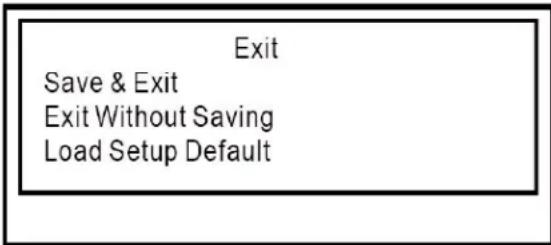
Figure 16.4 Exit menu
To open the Exit menu and save your changes:
- From any open system menu, press until the Exit menu appears.

OR
- From the System menu, select Exit and press ◀▶.
- Select Save & Exit and press 📋 to save your settings.
Load Setup Default
You can restore your system to factory settings from the Exit menu.
To load factory settings:
- From the Main Menu, select System and press 📄 . The System menu opens.
- Select Exit and press ◀▶.
- From the Exit menu, select Load Setup Default and press ◀►. The system immediately begins restoring the system to factory settings.
USB Backup
You can backup recorded video data from the system to a USB flash drive (not included). You can access USB Backup through direct Playback, or through Search and Event List in the system menus.
Note: You must connect a USB flash drive to the USB port on the front panel in order to use USB Backup.
To open USB Backup:
Playback
- Press the ▶/□ button to open the Event List.
- Select a file and press / _II to begin playback.
- Press . The USB Backup screen opens.
OR
Search
- Open the Setup menu. Login with your system password (by default, 111111).
- Select Search and press 📋. The Time Search screen opens.
- Enter a Start and End Time and press

to begin playback.
- Press . The USB Backup screen opens.
OR
Event List (System Menu)
- Open the System Menu, select Event List
and press

- Select a file and press // to begin playback.
- Press . The USB Backup screen opens.
Using USB Backup
To use USB Backup:
- Connect a USB flash drive to the USB port on the front panel.
- Begin Playback through direct Playback, Search, or the Event List.
- During playback, press . The USB Backup screen opens.
- Press 1 to set a Start Time. You can pause/play video, and increase/decrease playback speeds.
- Press 2 to set a Stop Time. The size of the backup file appears.
- Press 4 to start backup. The system scans the USB flash drive.
Note: If there is not enough space on the USB flash drive, the following message will appear: "CAPACITY IS NOT ENOUGH."
- Press 4 again to copy data to the USB flash drive. The system displays the estimated time remaining for file transfer.
- Once the system displays the message
"COMPLETE, press Ⓞ/■ to exit the Backup menu.
Note: Copied video files are saved as .VVF files.
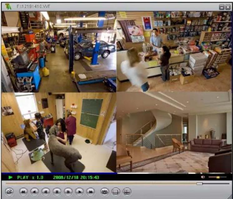
Lorex Client Software
The system comes with the Lorex Client application that lets you playback video files you have saved to a USB flash drive (not included)..
natural_image
Four-panel collage showing a retail store interior with furniture, staff, and interior spaces; no visible text or symbols.Figure 17.0 DVR Viewer main window
System Requirements
Prior to using Lorex Client, make sure your PC meets or exceeds the following system requirements:
| Requirement | |
| CPU PentiumTM | 4 or above |
| Operating System | Windows XP/Vista |
| Memory 512 MB | RAM |
| Video 16 MB of video memory | |
Using Lorex Client
Prior to using Lorex Client, make sure you have copied video data from the system to a USB flash drive (not included).
Launching Lorex Client
To open DVR Viewer:
-
Insert the software CD included with your system into your PC's CD-ROM or DVD-R/RW drive.
-
Double-click the file, vVF Player.exe. DVR Viewer opens.
Note: You can also copy this file to your PC.
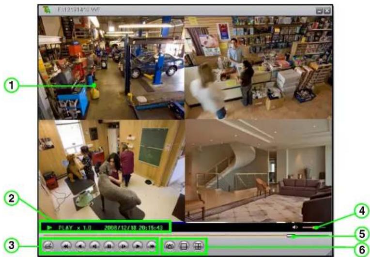
Figure 18.0 Lorex Client main screen
-
Main Display Screen: Displays video in single channel and Quad mode.
-
Display Information: Shows playback speed and date/stamp.
-
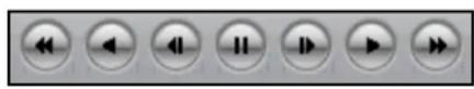
Control Buttons: Primary control buttons include the following:
• Click to open a saved video file (.VVF).
- Increase reverse playback speed (2X, 4X, 8X).
• :Rewind one frame and pause.
-
Click to pause playback.
• : Advance one frame and pause.
• :Click to start forward playback.
• : Increase forward playback (2X, 4X, 8X). -
Volume: Volume slider.
Note: Line-in audio required during original recording in order to hear volume during playback.
-
Playback Slider: Move the playback slider to jump forward or backward in the video file.
-
Still Capture & View mode buttons: Snapshot & View buttons include the following:
-
Click to take a screenshot of the DVR Viewer display screen—copy the image to MS Paint, Photoshop or another imaging application.
- Click to view in full-screen single channel.
- Click to view in Quad split-screen.
Playing Saved Video Files
Use Lorex Client to playback saved/backed up video files copied from the system a USB flash drive.
To playback saved files:
- Connect a USB flash drive with saved video data to your PC.
- Launch Lorex Client.
- Click 📄. In the new window, select the .VVF file and click Open. The file immediately begins playing (at 1X speed) in DVR Viewer.
Note: You can also right-click anywhere on the DVR Viewer main window and select Open file... or press F2 on your keyboard.
Playback Options
During playback, you have access to the following options:
Playback control buttons: Click any of the buttons along the bottom of the DVR Viewer main window to increase/decrease forward and reverse playback, pause, and play video frame-by-frame.
Change Display Mode On-the-Fly: From the DVR Viewer main window (by default, Quad split-screen mode), double click channels 1\~4 to view the respective channel in single-channel. Double-click again to return to Quad mode.
Note: You can also click a channel in Quad mode and then click ☐ to view it in single-channel. Click ☐ to return to Quad mode.
Playback Slider: Click and drag the slider to jump forward or backward in the file.
Sub-Menu
The sub-menu lets you access several options.
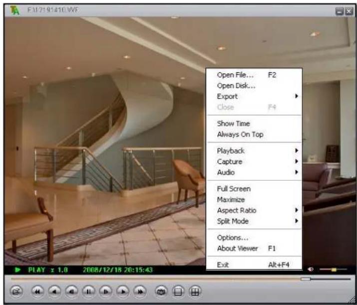
Figure 18.1 Lorex Client sub menu
To open the sub-menu:
-
Right-click anywhere on the main window to open the sub-menu. The sub-menu includes the following:
-
Open File: Select to open a .VVF file
- Open Disk: Select to view data from a connected hard drive previously installed in a DVR system (hard drive must be set as slave).
- Export: Select to convert the .VVF file to an .AVI file. AVI files are compatible with media players such a VLC and DiVx.
• Show Time: Show/hide the time from all channels during playback.
• Always On Top: Keep the Lorex Client window on top of other application windows. - Playback: Open the playback menu (same playback options as on the main window).
- Capture: Add markers to save a portion of the saved video as a . VVF file. See "Capture" on page 32.
• Audio: Volume up/down; Mute on/off.
• Full-Screen: View Lorex Client channel display in full screen (controls hidden).
- Maximize: View Lorex Client main window in large window (controls along bottom of window).
- Aspect Ratio: Set the screen size as either 640x448 or 640x544.
- Split-Mode: Set the display mode to Split 1 (single channel) or Split 4 (Quad split-screen).
- Options: Select to open the Lorex Client options menu. See "Options" on page 34.
- About Viewer: View application information for Lorex Client.
- Exit: Close Lorex Client.
Capture
Use the capture feature to save a portion of video from the original VVF file.
To capture video:
- Open Lorex Client. Open a saved video file.
- During playback, select a portion of the video you want to save. Pause playback.
- Right-click anywhere on the main window and select Capture>Marker In. Play video.
- Advance the video/select the end-point for the video. Right-click anywhere on the main window and select Capture>Marker Out.
- Right-click anywhere on the main window and select Capture>Export.
- In the Save As dialogue window, select a file name and save location and click Save.
Note: Captured files carry the file extension .VVF.
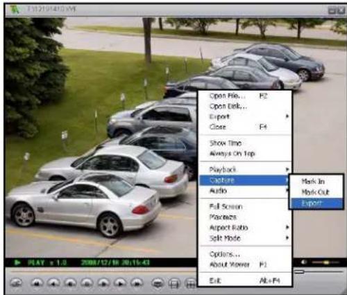
Figure 18.2 Capture sub menu
Please allow a few moments to save the captured video. This could take several moments depending on the size of the capture.
With the captured video now saved to your PC, you can use Lorex Client to export the file as an AVI for greater flexibility of playback among other media players.
Exporting to AVI
Lorex Client allows you export .VVF files to .AVI for increased flexibility when playing back the video in third-party media players, such as VLC™ and DivX Player™. Converting the file to AVI can be particularly useful if you need to provide authorities with copies of your video data if there is a security incident at your business or home.
Note: The DivX or XviD codec (not included) is required if viewing AVIs in Windows Media Player™.
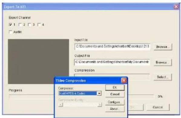
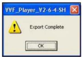
Figure 18.3 Exporting to AVI
To export video files:
- Open Lorex Client.
- Right-click anywhere on the main display screen and select Export>AVI.
- In the Export window, under Input File, click Browse to select the file to be exported (.VVF).
- Under Output File, click Browse to select a save location for the exported file (by default, output files are saved to the save location as the input file).
Note: Output files carry the default naming convention, CAPTURE-CH(channelnumber).avi.
- Under Export Channel, check/uncheck the boxes for channels 1\~4.
- Under Audio, check/uncheck the box to include/exclude audio in the file conversion.
- Under Compression, click Select. In the Video Compression window, select a compression type from the drop-down menu and click OK. See "Appendix 5: Compression Codecs" on page 41.
- In the Export window, click OK. File conversion begins. Exporting to AVI could take several moments depending on the number of channels being exported, the inclusion of audio, and the size of the original file.
Note: Depending on your compression type, windows may open windows showing the progress of the file conversion for each channel. When the files are finished exporting to AVI, you can close these windows.
Note: Lorex Client creates a placeholder file, dummy.avi in the Output folder.
Options
Use the Options window to configure general options, on-screen display, and the default path for still capture.
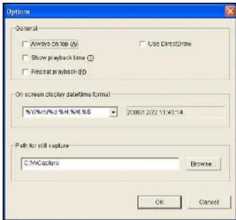
Figure 18.4 Options menu
To configure options:
-
Under General, check/uncheck the boxes to enable/disable the following:
-
Always on Top: Keep the Lorex Client window on top of other application windows. Shortcut Key, A.
• Show playback time: During playpack, show/hide the date-stamp. Shortcut Key, T. - Repeat playback: Repeat (loop) playback. Shortcut key, R.
- Use DirectDraw: Enable/disable DirectDraw to enhance visual quality during playback.
Note: DirectDraw is part of Microsoft DirectX.
- Under On screen display date/time format, select your desired format for the date and time from the drop-down menu. For example, yyyy/mm/dd, hh/mm/ss; or Month Day, AM/PM, hh/mm/ss yyyy.
- Under Path for still capture, click Browse to select a save location for the still image bitmap (.BMP) files. By default, C:\VxCapture.
- When you are finished, click OK to save your settings, or click Cancel to exit without saving.
Appendix 1: System Specifications
| Description Specification | |
| Video Format NTSC | PAL |
| Operating System RTOS | |
| VGA Output VGA | |
| Video Input 4 x BNC | (1Vp-p 75 ohms) |
| Audio Input 1 x RCA | line-in |
| Video Output 1 x BNC (Monitor Out) | |
| Audio Output 1 x RCA | A line-out |
| Language Multi-language | |
| Display Frame NTSC | 120 fps (4 x 30 fps)PAL: 100 fps (4 x 25 fps) |
| Recording Frame NT | SC: 60 fps max.PAL: 50 fps max. |
| Recording Resolution | NTSC: 640x224PAL: 640x272 |
| Display Resolution NT | TSC: 640x448PAL: 640x544 |
| Compression Format | MJPEGNormal: 12KB/frame; High: 15KB/frame; Highest: 20KB/frame |
| Hard Disk 3.5" SATA | (1 TB max.) |
| Backup USB (front panel) | |
| Power Supply 12V DC / 4 A (AC 100V~240V 50/60 Hz) | |
| Dimensions(WxDxH) | 220 mm x 228 mm x 48 mm8.66" x 8.99" x 1.89" |
| Weight 1.5 kg / 3.31 | bs |
As our products are subject to continuous improvement, Lorex Technology Inc. and its subsidiaries reserve the right to modify product design, specifications, and prices without notice and without incurring any obligation.
E&OE
Appendix 2: Full Connectivity Diagram
The following diagram outlines a general set of connections available with the DVR.
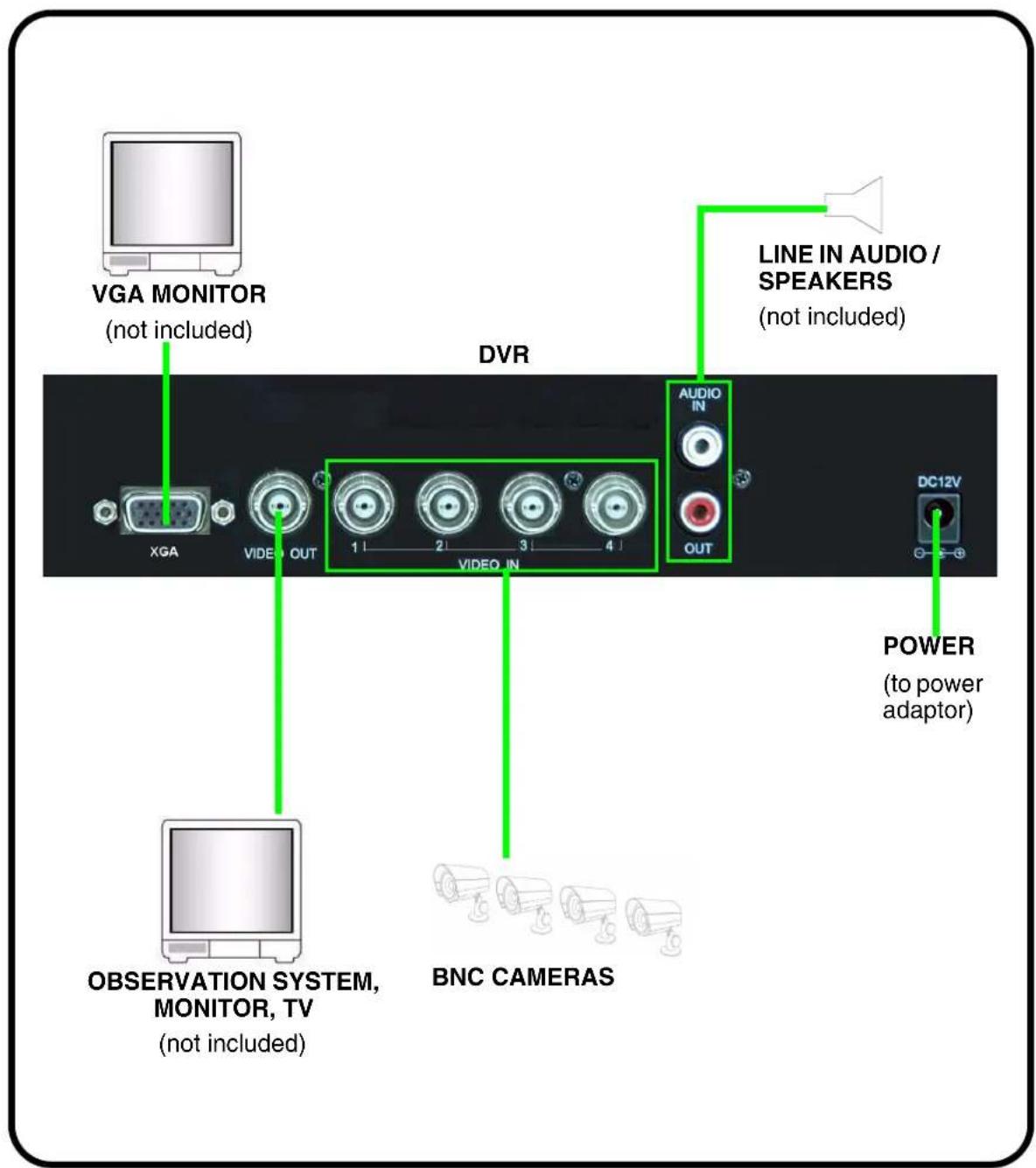
Figure 19.0 Full connectivity diagram
Appendix 3: Using Listen-in Audio
Listen-in audio allows you to listen to, and record live audio on the system. You can record one audio channel (mono) with an RCA (male) audio cable.
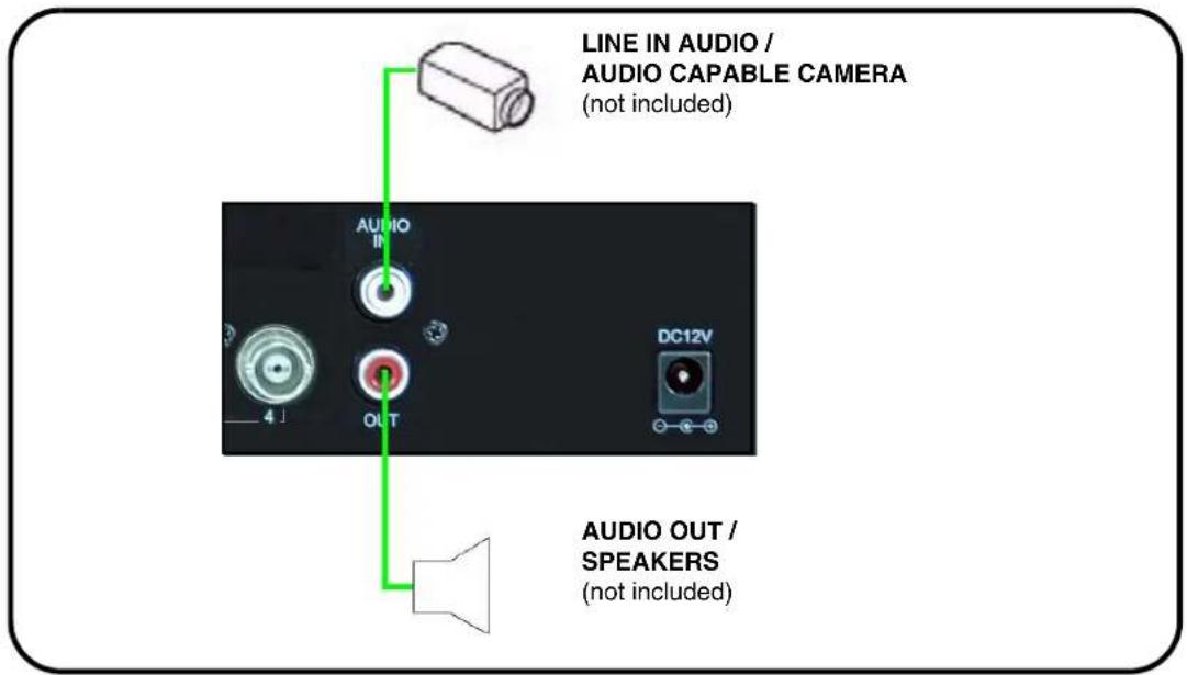
Figure 20.0 Audio connection diagram
To enable listen-in audio:
- Connect an RCA audio cable (male) from an audio capable camera to the AUDIO IN port on the rear panel.
-
Connect an RCA audio out cable (male) to the AUDIO OUT port on the rear panel.
-
From the Setup Menu, select Audio and press 📷. The Audio menu opens.
-
Select Record and press ◀▶ to turn audio recording On.
-
Press 📄 until the Exit menu appears. Select Save & Exit and press 🔒 to save your settings.
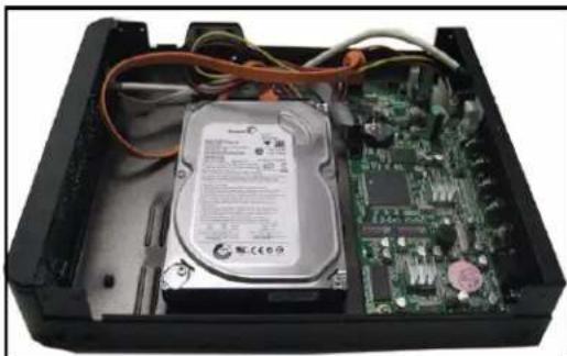
Appendix 4: Replacing the Hard Drive
The system comes with a pre-installed 3.5" SATA hard drive, however the unit will work with a replacement single hard drive (up to 1 TB).
Note: Make sure that the system is OFF and the power cable has been disconnected before changing the hard drive.
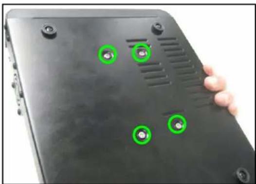
Removing the Hard Drive
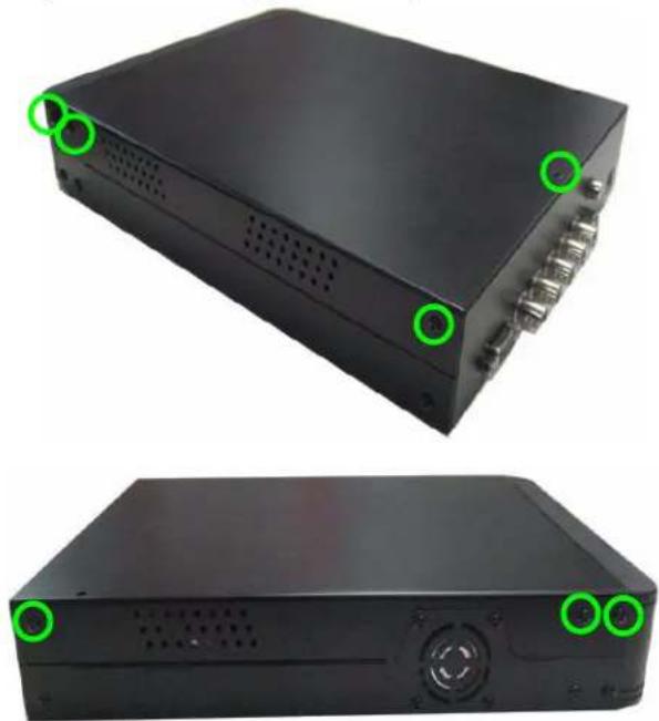
To remove the hard drive:
- Remove seven screws from the cover of the housing: three from the top half of each side panel; one from the top near the rear panel.
- Gently lift off the cover.
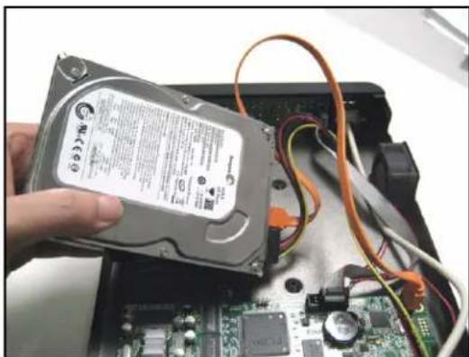
-
With your hand supporting the hard drive, turn the unit upside down. Remove the four mounting screws from the bottom of the unit. Turn the unit right side up.
-
Disconnect the power and data cables.
-
Remove the hard drive.
Note: Make sure to keep the two sets of screws (cover, mounting) in a safe place.
natural_image
Two views of a black electronic device with ports and ventilation slots, marked by green circular annotations (no text or symbols visible)Figure 21.0 Remove seven screws from cover
natural_image
Interior view of an open hard disk drive showing internal components like a hard disk, circuit board, and cable (no visible text or symbols)Figure 21.1 Remove cover.
natural_image
Close-up of a black electronic device with green circular annotations on its surface, held by a hand (no text or symbols visible)Figure 21.2 Support the HDD with your hand and remove mounting screws.
natural_image
Hand holding a hard disk drive with visible circuit board and wiring, no text or symbols presentFigure 21.3 Carefully remove the HDD from housing.
Replacing the Hard Drive
To replace the hard drive:
- Firmly connect the power and data cables to the replacement SATA hard drive—each cable can only connect in one way.
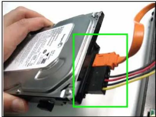
natural_image
Close-up of a hand holding a hard disk with attached orange cable and wiring (no visible text or symbols)Figure 21.4 Connect the power and data cables.
- Carefully place the hard drive in the housing.
Note: Make sure not to damage any of the cables when placing the hard drive in the housing.
Note: Make sure no cables are caught beneath the drive.
-
With your hand supporting the hard drive, turn the housing upside down: replace the four screws on the bottom of the housing.
-
Turn the housing right side up. Replace the cover, making sure to slide the cover toward the front panel until flush.
-
Replace the screw on the top panel (x1) and side panels (x6).
-
Reconnect all cameras and cables.
-
Power on the system. If you have installed a new hard drive, you must format the drive before using the system.
Note: The system will detect the hard drive a few seconds after powering on the system. The system will prompt you if the hard drive is not detected.
Formatting the Hard Drive
Use Hard Disk Setup in the System menu to format the internal hard drive.
Note: You must stop recording before attempting to format the hard drive.
ATTENTION: Formatting erases all recorded video data on the hard drive. Formatting cannot be undone. System settings are not affected by formatting.
To format the hard drive:
- Open the Setup menu. Select System and press . The System menu opens.
- From the System menu, select Hard Disk Setup and press .
- Select Format HDD and press ◀▶.
- Enter your 6-character system password. The system begins formatting the hard drive. This could take several moments depending on the size of your system's hard drive.
Once formatting is complete, the system will return to Live Mode.
Appendix 5: Compression Codecs
When exporting a .VVf file to .AVI, you can choose any of the following codecs for compression:
• Cinepak Codec by Radius
- Intel 4:2:0 Video V2.50
- Intel Indeo(R) Video R3.2
- Intel IYUV Codec
- Microsoft RLE
- Microsoft Video 1
• Microsoft H.263 Video Codec
• Microsoft H.261 Video Codec
- Indeo® Video 5.10
• Sunplus 32-bit Compressor
• DivX® 6.1.1 Codec (1 Logical)
• DivX® 6.1.1 YV12 Decoder
• Xvid MPEG-4 Codec
• Full Frames (uncompressed)
Note: Video Codecs for playback are NOT supplied with this software. Codecs can be downloaded from such sites as www.microsoft.com or www.divx.com
Troubleshooting
When a malfunction occurs, it may not be serious and can be corrected easily. The following describes the most common problems and solutions. Please refer to the following before calling Lorex Technical Support:
| Possible Causes Solutions | ||
| • DVR Unit is not receiving power, or is not powering up | • Cable from power adaptor is loose or is unplugged | • Confirm that all cables are connected correctly• Confirm that the power adaptor is securely connected to the back of the unit |
| • Cables are connected, but DVR unit is not receiving sufficient power | • Confirm that the unit is powered on (LED indicators on the front should be ON)• If the unit is connected through a power bar or surge protector, try bypassing the bar and connecting the power directly to the wall outlet• Confirm that there is power at the outlet:• Connecting the power cable to another outlet• Test the outlet with another plugged device (such as an electric calculator or phone charger) | |
| • Remote control is not detected by the system• There are no batteries• Hard drive is not detected by the system | • Batteries in the remote control are drained | • Install a fresh CR2025 lithium battery in the remote control |
| • Hard drive cables are loose or not properly connected | • Remove the houseing and check that hard drive cables are firmly connected | |
| • There is no hard drive in the system | • Open the housing and install a 3.5" SATA hard drive | |
| Hard drive is full (0%) and the unit is no longer recording | • Overwrite is not enabled • Turn On | • Overwrite on. Setup>System>Hard Disk Setup. |
Troubleshooting (cont'd.)
| Error Possible Causes Solutions | ||
| • There is no picture on selected channels / camera picture is not being displayed | • Camera cables are loose or have become disconnected | • Check the camera video cable and connections• Disconnect and reconnect the cable at the DVR and at the Camera• Try moving the camera to another channel or use another cable |
| • The image on the DVR appears, but does not have sound | • Audio cables are loose or have been disconnected | • Check the AUDIO connections to the DVR |
| • Audio channels are disabled in the system menu | • Check the Configurations: Setup Menu>Audio | |
| • Volume on external speakers (not included) is low or off | • Increase volume on external speakers (not included) | |
| LOREX PRODUCT/LIMITED WARRANTY | LUXE ITEMS:THE WRNTY SETS NO INCOME—Buses, LDS, and Betachies—Lores, obligations under the warranty shall be limited to clarifies, respectively under this is of any warranty, insured or expressed is linked to request, approval or refund, as set forth above. These licenses are the last ten items in accordance with each other's rights, which are not required to receive any right to pay for any benefit from the Product or its owners and may be a secure deal or a secure deal for the Product or its owners and may be a secure deal for the Product or its owners and may be a secure deal for the Product or its owners and may be a secure deal for the Product or its owners and may be a secure deal for the Product or its owners and may be a secure deal for the Product or its owners and may be a secure deal for the Product or its owners and may be a secure deal for the Product or its owners and may be a secure deal for the Product or its owners and may be a secure deal | |
| ARGARANTIE LIMITED DES PRODUCTS LOREX | 1. Name of agencies, which are not required to receive any right to pay for any benefit from the Product or its owners and may be a secure deal or a secure deal for the Product or its owners and may be a secure deal for the Product or its owners and may be a secure deal for the Product or its owners and may be a secure deal for the Product or its owners and may be a secure deal for the Product or its owners and may be a secure deal for the Product or its owners and may be an intermediate class or a certain class or a certain class or a certain class or a certain class or a certain class or a certain class or a certain class or a certain class or a certain class or a certain class or a certain class or a certain class or a certain class or a certain class or a certain class or a certain class or a certain class or a certain class or a certain class or a certain class or a certain class or a certain class or a certain class or a certain class or a certain class or a specific class or a certain class or a certain class or a certain class or a certain class or a certain class or a certain class or a certain class or a certain class or a certain class or a certain class or a certain class or a certain class or a certain class or a certain class or a certain class or a certain class or a certain class or a certain class or a certain class or a certain class or a certain class or a certain class or a certain class or a certain class or a different class or a certain class or a certain class or a certain class or a certain class or a certain class or a certain class or a certain class or a certain class or a certain class or a certain class or a certain class or a certain class or a certain class or a certain class or a certain class or a certain class or a certain class or a certain class or a certain class or a certain class or a certain class or a certain class or a certain class or a certain class or a similar class or a certain class or a certain class or a certain class or a certain class or a certain class or a certain class or a certain class or a certain class or a certain class or a certain class or a certain class or a certain class or a certain class or a certain class or a certain class or a certain class or a certain class or a certain class or a certain class or a certain class or a certain class or a certain class or a certain class or a certain class or a other than some other than some other than some other than some other than some other than some other than some other than some other than some other than some other than some other than some other than some other than some other than some other than some other than some other than some other than some other than some other than some other than some other than some other than some other than some other than some other than some other than some other than some other than some other than some other than some other than some other than some more than some more than some more than some more than some more than some more than some more than some more than some more than some more than some more than some more than some more than some more than some more than some more than some more than some more than some more than some more than some more than some more than some more than some more than some more than some more than some more than some more than some more than some more than some more than some more than some more than some more that we have not applied any right to pay for any benefit from the Product or its owners and may be a secure deal or a secure deal for the Product or its owners and may be a secure deal for the Product or its owners and may be a secure deal for the Product or its owners and may be a secure deal for the Product or its owners and may be a secure deal for the Product or its owners and may be a secure deal for the Product or its owners and may be a secure deal for the Product or his owners and may be a secure deal for the Product or his owners and may be a secure deal for the Product or his owners and may be a secure deal for the Product or his owners and may be a secure deal for the Product or his owners and may be a secure deal for the Product or his owners and may be a secure deal for the Product or his owners and may be a secure deal for the Product or his owners and may be a secure deal for the Product or his owners and may have no payment to claim on this warranty, provided by the Product required services under its warranty, to the purchase of your warranty may not apply to you. This limited warranty gives you also pay for you only pay for you only pay for you only pay for you only pay for you only pay for you only pay for you only pay for you only pay for you only pay for you only pay for you only pay for you only pay for you only pay for you only pay for you only pay for you only pay for you only pay for you only pay for you only pay for you only pay for you only pay for you only pay for you only pay for you only pay for you only pay for you sole pay for you only pay for you only pay for you only pay for you only pay for you only pay for you only pay for you only pay for you only pay for you only pay for you only pay for you only pay for you only pay for you only pay for you only pay for you only pay for you only pay for you only pay for you only pay for you only pay for you only pay for you only pay for you only pay for you only pay for you only pay for you one pay for you only pay for you only pay for you only pay for you only pay for you only pay for you only pay for you only pay for you only pay for you only pay for you only pay for you only pay for you only pay for you only pay for you only pay for you only pay for you only pay for you only pay for you only pay for you only pay for you only pay for you only pay for you only pay for you only pay for you only pay for you all pay for you only pay for you only pay for you only pay for you only pay for you only pay for you only pay for you only pay for you only pay for you only pay for you only pay for you only pay for you only pay for you only pay for you only pay for you only pay for you only pay for you only pay for you only pay for you only pay for you only pay for you only pay for you only pay for you only pay for you only pay for you both pay for you only pay for you only pay for you only pay for you only pay for you only pay for you only pay for you only pay for you only pay for you only pay for you only pay for you only pay for you only pay for you only pay for you only pay for you only pay for you only pay for you only pay for you only pay for you only pay for you only pay for you only pay for you only pay for you only pay for you only pay for you every pay for you only pay for you only pay for you only pay for you only pay for you only pay for you only pay for you only pay for you only pay for you only pay for you only pay for you only pay for you only pay for you only pay for you only pay for you only pay for you only pay for you only pay for you only pay for you only pay for you only pay for you only pay for you only pay for you only pay for you only pay for you any pay for you only pay for you only pay for you only pay for you only pay for you only pay for you only pay for you only pay for you only pay for you only pay for you only pay for you only pay for you only pay for you only pay for you only pay for you only pay for you only pay for you only pay for you only pay for you only pay for you only pay for you only pay for you only pay for you only pay for you only pay for you total pay for you only pay for you only pay for you only pay for you only pay for you only pay for you only pay for you only pay for you only pay for you only pay for you only pay for you only pay for you only pay for you only pay for you only pay for you only pay for you only pay for you only pay for you only pay for you only pay for you only pay for you only pay for you only pay for you only pay for you only pay for you daily pay for you only pay for you only pay for you only pay for you only pay for you only pay for you only pay for you only pay for you only pay for you only pay for you only pay for you only pay for you only pay for you only pay for you only pay for you only pay for you only pay for you only pay for you only pay for you only pay for you only pay for you only pay for you only pay for you only pay for you only pay for you multiple pay for you only pay for you only pay for you only pay for you only pay for you only pay for you only pay for you only pay for you only pay for you only pay for you only pay for you only pay for you only pay for you only pay for you only pay for you only pay for you only pay for you only pay for you only pay for you only pay for you only pay for you only pay for you only pay for you only pay for you only pay for you primary pay for you only pay for you only pay for you only pay for you only pay for you only pay for you only pay for you only pay for you only pay for you only pay for you only pay for you only pay for you only pay for you only pay for you only pay for you only pay for you only pay for you only pay for you only pay for you only pay for you only pay for you only pay for you only pay for you only pay for you only pay for you single pay for you only pay for you only pay for you only pay for you only pay for you only pay for you only pay for you only pay for you only pay for you only pay for you only pay for you only pay for you only pay for you only pay for you only pay for you only pay for you only pay for you only pay for you only pay for you only pay for you only pay for you only pay for you only pay for you only pay for you only pay for you monthly pay for you only pay for you only pay for you only pay for you only pay for you only pay for you only pay for you only pay for you only pay for you only pay for you only pay for you only pay for you only pay for you only pay for you only pay for you only pay for you only pay for you only pay for you only pay for you only pay for you only pay for you only pay for you only pay for you only pay for you only pay for you almostly pay for you only pay for you only pay for you only pay for you only pay for you only pay for you only pay for you only pay for you only pay for you only pay for you only pay for you only pay for you only pay for you only pay for you only pay for you only pay for you only pay for you only pay for you only pay for you only pay for you only pay for you only pay for you only pay for you only pay for you only pay for you slightly pay for you only pay for you only pay for you only pay for you only pay for you only pay for you only pay for you only pay for you only pay for you only pay for you only pay for you only pay for you only pay for you only pay for you only pay for you only pay for you only pay for you only pay for you only pay for you only pay for you only pay for you only pay for you only pay for you only pay for you only pay for you several pay for you only pay for you only pay for you only pay for you only pay for you only pay for you only pay for you only pay for you only pay for you only pay for you only pay for you only pay for you only pay for you only pay for you only pay for you only pay for you only pay for you only pay for you only pay for you only pay for you only pay for you only pay for you only pay for you only pay for you only pay for you-only pay for you only pay for you only pay for you only pay for you only pay for you only pay for you only pay for you only pay for you only pay for you only pay for you only pay for you only pay for you only pay for you only pay for you only pay for you only pay for you only pay for you only pay for you only pay for you only pay for you only pay for you only pay for you only pay for you only pay for you only pay for you solo pay for you only pay for you only pay for you only pay for you only pay for you only pay for you only pay for you only pay for you only pay for you only pay for you only pay for you only pay for you only pay for you only pay for you only pay for you only pay for you only pay for you only pay for you only pay for you only pay for you only pay for you only pay for you only pay for you only pay for you only pay for you primarily pay for you only pay for you only pay for you only pay for you only pay for you only pay for you only pay for you only pay for you only pay for you only pay for you only pay for you only pay for you only pay for you only pay for you only pay for you only pay for you only pay for you only pay for you only pay for you only pay for you only pay for you only pay for you only pay for you only pay for you only pay for you or only pay for you only pay for you only pay for you only pay for you only pay for you only pay for you only pay for you only pay for you only pay for you only pay for you only pay for you only pay for you only pay for you only pay for you only pay for you only pay for you only pay for you only pay for you only pay for you only pay for you only pay for you only pay for you only pay for you only pay for you only pay for |
LOREX
It's all on the Web!
Specification Sheets

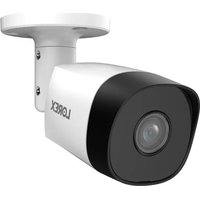
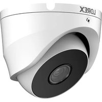

- CAUTION
- Important Safeguards
- Installation
- Service
- Use
- General Precautions
- FCC CLASS B NOTICE
- Note
- Features
- Table of Contents
- Getting Started 1
- Basic Setup 2
- Front Panel 3
- Rear Panel 4
- Remote Control 5
- Menu Navigation Tips & Tricks 5
- Installing Cameras 6
- Starting the System 8
- Logging in to the System 11
- Setting the Date and Time 12
- Recording 13
- Playback 14
- Searching for Recorded Video 16
- Using the Setup Menu 19
- Hard Disk Setup 24
- USB Backup 27
- Using Lorex Client 29
- Appendix 1: System Specifications ....35
- Appendix 2: Full Connectivity Diagram 36
- Appendix 3: Using Listen-in Audio 37
- Appendix 4: Replacing the Hard Drive ....38
- Appendix 5: Compression Codecs .... 41
- Troubleshooting 42
- Getting Started
- Basic Setup
- Connect the Cameras
- Connect the Monitor
- Connect the Power Adaptor
- Optional
- Front Panel
- Rear Panel
- Remote Control
- Menu Navigation Tips & Tricks
- Installing Cameras
- Installation Warning
- Assembling the Camera Stand
- Connecting BNC Cameras
- Camera Connections
- Starting the System
- On-Screen Display
- Display Modes
- Auto Sequence Mode
- Logging in to the System
- Entering Your Password
- Setting the Date and Time
- Recording
- Motion Recording
- Manual Recording
- Recording Audio
- Playback
- Press
- Searching for Recorded Video
- Time Search
- Event List
- Using the Setup Menu
- TIP!
- Camera
- Covert Channel Display
- Record
- Motion Detection
- Motion Area
- Screen
- Audio
- System
- Hard Disk Setup
- Overwrite Enable
- Format HDD
- Password Change
- Time Set
- Loss Alarm
- F/W Upgrade
- Search
- Exit
- OR
- USB Backup
- Event List (System Menu)
- Using USB Backup
- Lorex Client Software
- System Requirements
- Using Lorex Client
- Launching Lorex Client
- Playing Saved Video Files
- Playback Options
- Sub-Menu
- Capture
- Exporting to AVI
- Options
- To configure options:
- Appendix 2: Full Connectivity Diagram
- Appendix 3: Using Listen-in Audio
- Appendix 4: Replacing the Hard Drive
- Removing the Hard Drive
- Replacing the Hard Drive
- Formatting the Hard Drive
- Appendix 5: Compression Codecs
- Troubleshooting
- Troubleshooting (cont'd.)
- It's all on the Web!
Brand : Lorex
Model : L114V251
Category : Surveillance Camera