Smart 2 - Smart Home ECOFLOW - Free user manual and instructions
Find the device manual for free Smart 2 ECOFLOW in PDF.

| Product Type | Smart Home Distribution Panel |
| Brand | EcoFlow |
| Model | Smart Home Panel 2 (Smart 2) |
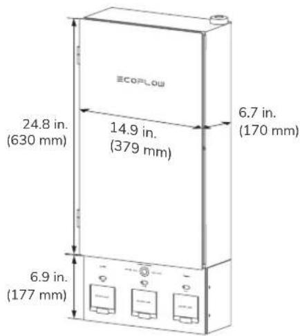
| Dimensions (L × H × D) | 823.7 × 379 × 170 mm |
| Weight | 24 kg |
| Rated voltage | 120/240 V (split phase) |
| Panel nominal current | 100 A max |
| Storage nominal current | 90 A max |
| Number of load circuits | 12 |
| Enclosure type | NEMA TYPE 3R (panel), NEMA TYPE 1 (battery enclosure) |
| Operating temperature | -30 °C to 50 °C |
| Operating humidity | Up to 100% RH with condensation |
| Maximum altitude | ≤ 2000 m |
| Overvoltage category | IV |
| Communication | Ethernet, Wi-Fi (2.4 GHz), Bluetooth |
| Compatible generator | 120 V single-phase / 240 V split-phase (3-12 kW) |
| Compatible batteries | EcoFlow DELTA Pro (max 2), DELTA Pro Ultra (max 3) |
| Compatible circuit breakers | Eaton, Square D, Siemens, GE (see manual for models) |
| Main functions | Grid/generator switching, load management, app monitoring, mechanical interlock |
| Safety | Mechanical interlock, emergency stop, error indicators, surge protection |
| Installation | Indoor or outdoor (rainproof panel) |
| Included accessories | Input/output cable, installation guide, glass door, safety cover |
| Maintenance | Clean with a soft cloth without solvents |
| Compliance | FCC Part 15, IC RSS, UL |
Frequently Asked Questions - Smart 2 ECOFLOW
User questions about Smart 2 ECOFLOW
0 question about this device. Answer the ones you know or ask your own.
Ask a new question about this device
Download the instructions for your Smart Home in PDF format for free! Find your manual Smart 2 - ECOFLOW and take your electronic device back in hand. On this page are published all the documents necessary for the use of your device. Smart 2 by ECOFLOW.
USER MANUAL Smart 2 ECOFLOW
For the latest installation guide, owner's manual, and tutorial video, please scan the QR code or visit: https://manuals.ecoflow.com/product/smart-home-panel-2
CONTENTS SOMMAIRE
1 Safety Instructions
1 Disclaimer
1 Symbol Conventions
1 FCC Warning
1 IC Warning
1 Technical Specifications
2 Product Overview
2 With Deadfront Cover Installed
3 With Deadfront Cover Removed
4 What's In The Box
4 What You Need
4 How to Install
4 Dimension
5 System Overview
5 Installation Scenarios
6 Mounting Options
7 Internet Access
7 Choosing Cable Entry
8 Scenario 1: Installing the Entire SHP2 Indoors
9 Scenario 2: Installing the Panel and Battery Connection Box Separately
11 Wiring
11 Removing the Interlock
11 Installing Circuit Breakers
11 Connecting the Grid Conductors
12 Connecting the Generator Conductors
12 Connecting the Home Load Conductors
12 Connecting Communications Cables (If Needed)
12 Checking Connection
13 Completing Installation
13 Installing the Interlock
13 Installing the Deadfront Cover
14 Installing the Glass Door
14 Energizing
14 Internet and Initialization Setup
15 LED Indication
15 Locking the Panel
16 Connecting And Using Generator
16 Connecting a Generator
16 Using Interlock
16 Manually Switching Grid Supply And Backup
17 Connecting With Battery Storage
17 Circuit Breaker Compatibility
17 Eaton
18 Square D
18 Siemens
18 GE
Please read the product document and ensure that you understand it fully before using the product. After reading this document, keep it for future reference. Improper use of this product may cause serious injury to yourself or others, or cause product damage and property loss. Once you use this product, it is deemed that you understand, approve and accept all the terms and content in this document. EcoFlow is not liable for any loss caused by the user's failure to use the product in compliance with the product document.
In compliance with laws and regulations, EcoFlow reserves the right to the final interpretation of this document and all documents related to the product. This document is subject to changes (updates, revisions, or termination) without prior notice. Please visit EcoFlow's official website to obtain the latest product information: https://www.ecoflow.com/.
Symbol Conventions
| Symbol Description | |
| Indicates a hazard with a medium level of risk which, if not avoided, could result in death or serious injury. | |
| Indicates a hazard with a low level of risk which, if not avoided, could result in minor or moderate injury. | |
| NOTICE | Indicates important or additional information. |
| The position for connecting the protection ground cable. | |
| CAUTION, RISK OF ELECTRIC SHOCK. | |
| Caution, risk of danger. | |
| Refer to the operation instructions. | |
WARNING
- Only qualified electrical personnel should install or service the product.
- Please read the Installation Guide carefully before installing, operating, or servicing this product.
- Installation of this product must conform to local standards, national electrical safety standards, and the manufacturer's instructions.
-
Specifications of self-provided cables should meet the requirements of the Installation Guide and local regulations.
-
The AC cables are high voltage cables. Risk of death or serious injury due to electric shock.
-
There is a high possibility of electric shock or serious burns due to the high voltage in the product.
-
Use appropriate personal protective equipment (PPE) and follow safe electrical work practices.
-
Do not touch exposed wires with your hands.
-
Be cautious to prevent injury when moving heavy objects. Wear personal protective equipment such as protective gloves and shoes when manually moving the product.
-
Do not install or operate the equipment in extreme weather events such as lightning, snow, heavy rain, strong wind, etc.
-
Do not install or operate the product in an area where flammable or explosive materials are stored.
-
Inspect the product and cables for damage before installing. Do not install the product or cables if damaged in any way.
-
Turn off all power supplying this product before installation. Disconnect each circuit individually before servicing.
-
Always use a properly rated voltage sensing device to confirm that the power is off.
-
During the drilling process, cover the interior product to prevent debris from falling into the product, and clear the debris after drilling to prevent interference with the equipment.
-
Do not damage, smear or cover any warning labels on the device. All labels must be visible after installation.
-
Before operating the product, check the electrical connections to ensure that the product is reliably and permanently grounded.
-
Do not place any kind of objects on top of the product during operation.
-
To completely de-energize the product, you must turn off the upstream breakers as well as physically unplug all EcoFlow DELTA Pro series. Failure to do so may present a shock hazard.
-
Do not place or install flammable or potentially explosive objects near the product or in explosive atmospheres.
-
Do not insert foreign objects into any part of the equipment.
-
Do not connect life-support systems, medical equipment, or any other equipment use where product failure could lead to injury to persons or loss of life to circuits which can be remotely switched.
-
Install the product in a location that prevents damage from flooding. Ensure that no water sources are above or near the product, including downspouts, sprinklers, or faucets.
-
If needed, replace all devices, doors, and covers before turning on the power.

CAUTION
- In the case of cable damage, it must be replaced by the manufacturer, customer service or qualified personnel to prevent a safety hazard.
- Do not use solvents to clean the product.
- The product must be disposed of according to local codes and regulations.
- This product is not intended to be used as a service disconnect.
- Do not use parts or accessories other than those specified for use with the product.
- When installing the product, the screws need to be tightened according to the specification torque using a special tool.
- Keep out of reach of children or animals.
- This product is designed for residential use only.
FCC Warning
This device complies with part 15 of the FCC Rules. Operation is subject to the following two conditions:
(1) This device may not cause harmful interference, and (2) this device must accept any interference received, including interference that may cause undesired operation.
Any Changes or modifications not expressly approved by the party responsible for compliance could void the user's authority to operate the equipment.
Note: This device has been tested and found to comply with the limits for a Class B digital device, pursuant to part 15 of the FCC Rules. These limits are designed to provide reasonable protection against harmful interference in a residential installation.
This equipment generates uses and can radiate radio frequency energy and, if not installed and used in accordance with the instructions, may cause harmful interference to radio communications. However, there is no guarantee that interference will not occur in a particular installation. If this equipment does cause harmful interference to radio or television reception, which can be determined by turning the product off and on, the user is encouraged to try to correct the interference by one or more of the following measures:
-Reorient or relocate the receiving antenna.
-Increase the separation between the product and receiver.
-Connect the product into an outlet on a circuit different from that to which the receiver is connected.
-Consult the dealer or an experienced radio/TV technician for help.
This equipment complies with FCC radiation exposure limits set forth for an uncontrolled environment.
This equipment should be installed and operated with minimum distance 20 cm between the radiator & your body.
IC Warning
This device complies with Industry Canada licence-exempt RSS standard(s). Operation is subject to the following two conditions:
(1) this device may not cause interference, and
(2) this device must accept any interference, including interference that may cause undesired operation of the device.
This Class B digital apparatus complies with Canadian ICES-003. IC RF Statement:
When using the product, maintain a distance of 20 cm from the body to ensure compliance with RF exposure requirements.
Technical
Specifications
| AC voltage (nominal) 120V/240V | |
| Feed-in type Split phase | |
| Maximum current rating 100A panel / 90A storage | |
| Busbar rating 120A | |
| Maximum input short-circuit current | 10kA |
| Operating temperature -30°C to 50°C (-22°F to 122°F) | |
| Operating humidity Up to 100% | RH, condensing |
| Altitude ≤ 2,000 m (6,562 ft) | |
| Overvoltage category IV | |
| Enclosure type | NEMA TYPE 3R rainproof (distribution panel)NEMA TYPE 1 (battery connection box) |
| Number of load branches 12 | |
| Communication | Ethernet, Wi-Fi, and Bluetooth* |
| Wi-Fi | Frequency range:20M: 2412 - 2472 MHz40M: 2422- 2462 MHzMaximum output power: ≤ 16.5 dBm |
| Bluetooth* | Frequency range: 2402-2480MHzMaximum output power: ≤ 8.76 dBm |
| Weight | 52.9 lb (24 kg) |
| Dimensions | 32.4 x 14.9 x 6.7 in. (823.7 x 379 x 170 mm) |
| Compatible generator | 120V single phase / 240V split phase (3-12kW) |
With Deadfront Cover Installed
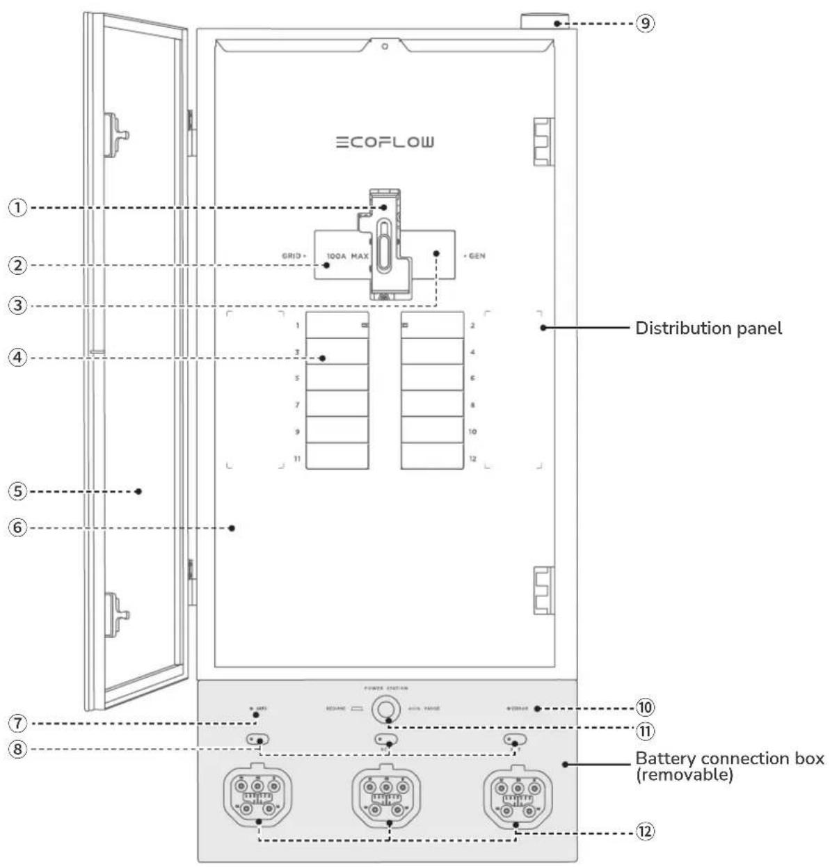
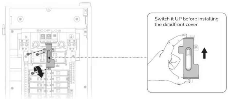
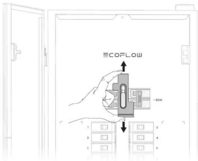
① Interlock (can be slid up/down to ensure that only one main circuit breaker to be in the ON position at any time)
② Main circuit breaker (grid)
③ Main circuit breaker (generator)
④ Branch circuit breaker
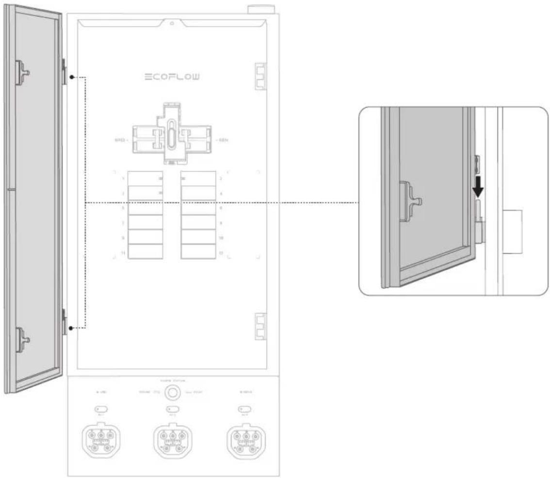
⑤ Glass door
⑥ Deadfront cover
⑦ Grid indicator
⑧ Power input/output button and storage indicator
⑨ Antenna (works with the EcoFlow app)
⑩ Error indicator
⑪ Emergency stop button
⑫ Power input/output port
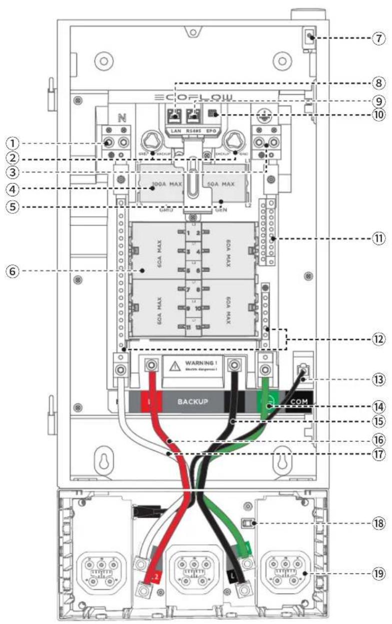
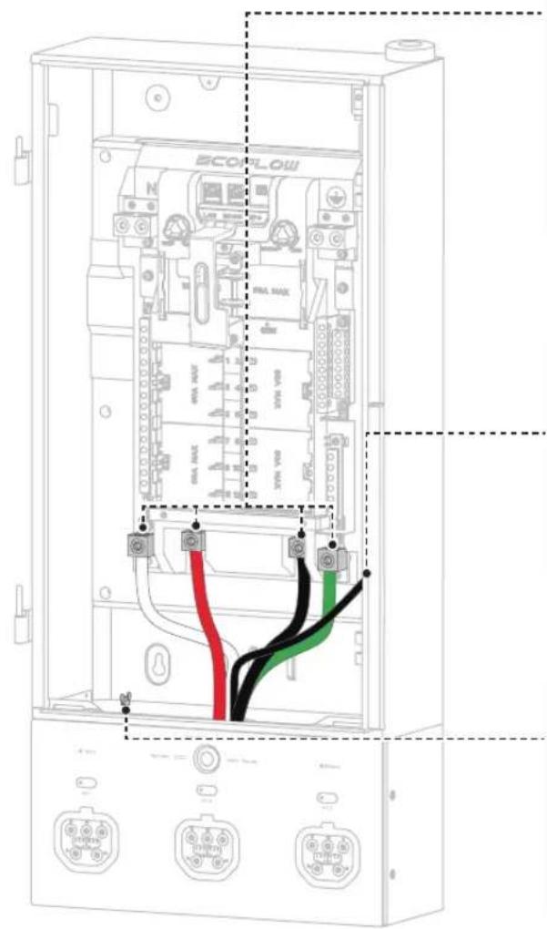
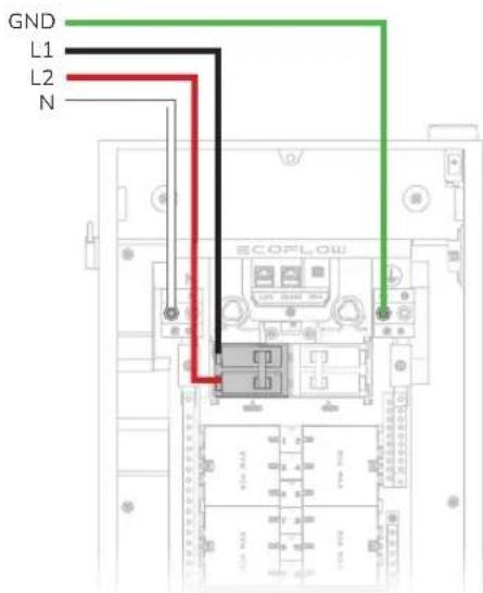
① Grid & generator neutral lugs
② Relay switching knob
③ Grid & generator ground lugs
④ Grid supply (L1, L2)
⑤ Generator supply (L1, L2)
⑥ 12 Loads (branch circuits) (L1, L2)
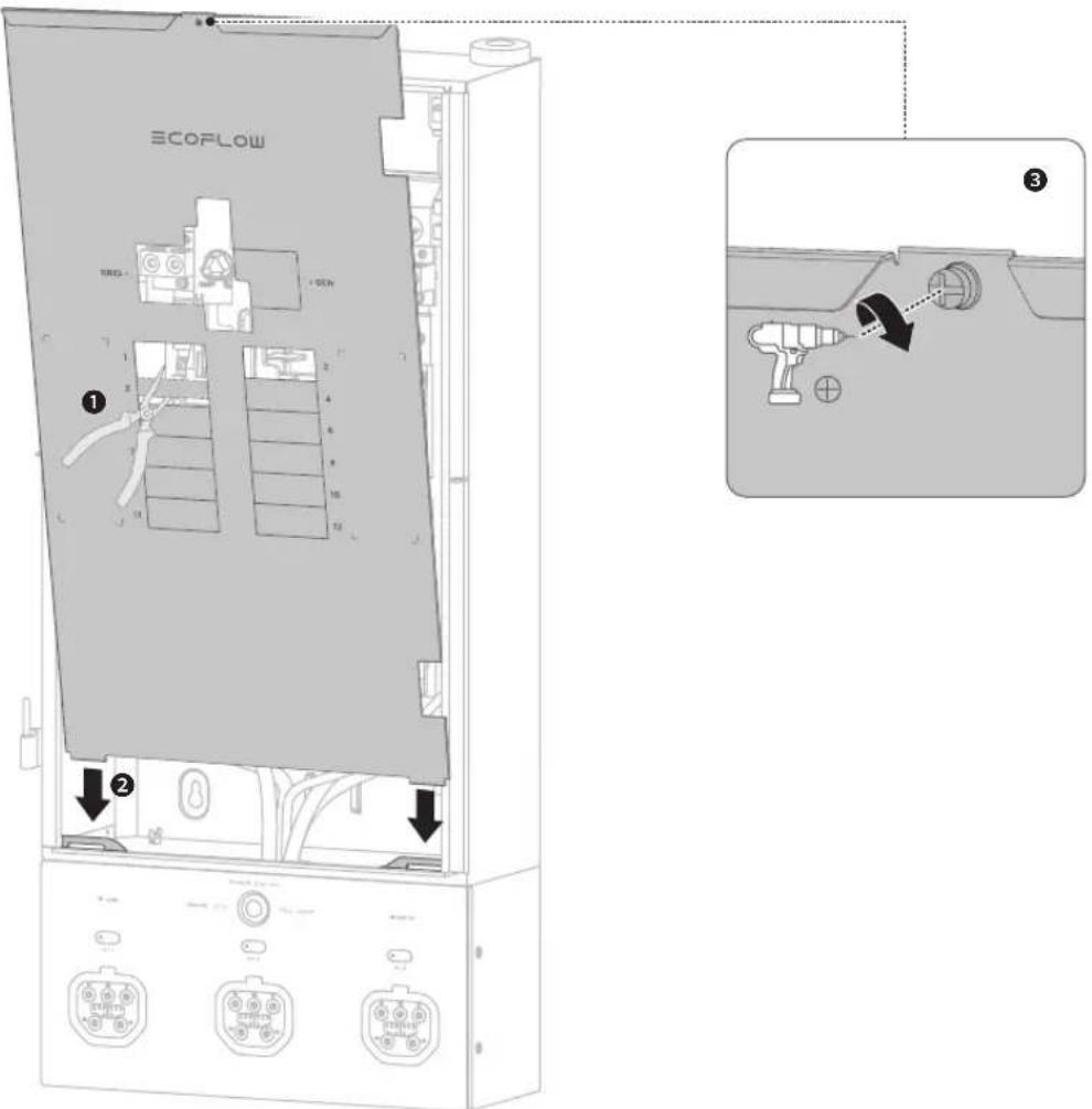
⑦ Deadfront switch (Triggered to power off the "power input/output port" when removing deadfront cover)
⑧ Ethernet port
⑨ RS485 port
⑩ EPO port
⑪ Load ground bus bar
⑫ Load neutral bus bar
⑬ Internal communication (COM) cable
⑭ Backup ground power cable
⑮ Backup L1 power cable
⑯ Backup L2 power cable
⑰ Backup neutral power cable
⑱ Auxiliary power port
⑲ Power input/output port
A ×1
Smart Home Panel 2 (glass door and deadfront cover packaged separately)
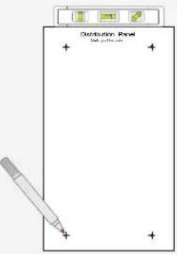
B ×1
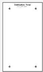
Marking-off template EcoFlow Power Input/Output Cable
C×1
What
You Need
WARNING
- Use appropriate personal protective equipment (PPE) and follow safe electrical work practices.
·Essentials
Main circuit breaker: 100A for grid, 50A for generator
Branch circuit breaker: Max. 60A, 1 in, AFCI/GFCI supported, plug-on neutral unsupported
See "Circuit Breaker Compatibility" for details.
-Optionals
If you need to install the battery connection box individually:
Power cables: 2 AWG, 6 AWG
CAT6, 568B straight-through shielded network cable :
≤787 in. (20 m)
Conduit fitting: 1-1/2 in.
If you need to connect a generator:
Generator main circuit breaker: 50A
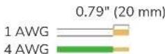
Cables for generator supply: AWG 8 AWG
Inlet box

Cables for grid supply: 1 AWG, 4 AWG
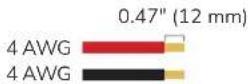
Cables for home loads: 14 AWG - 4 AWG, 14 AWG - 6 AWG
Cable for Ethernet communication : CAT6, T568B straight-through
Hydraulic hole puncher (used for cable entry)

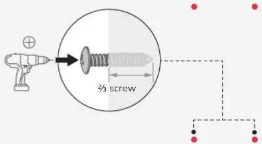
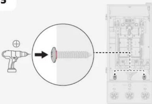
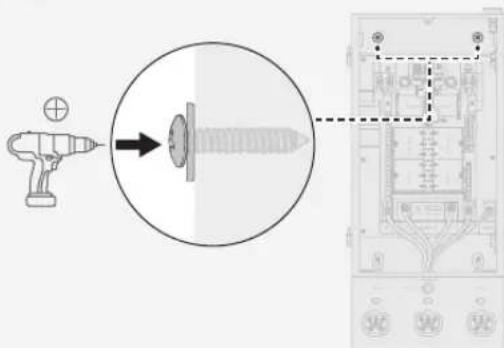
Screw ST5.5x32 (used for mounting Smart Home Panel 2)

Sealing washer (outside diameter 0.79 in. and inside diameter 0.24 in.)
How to
Install
Dimension
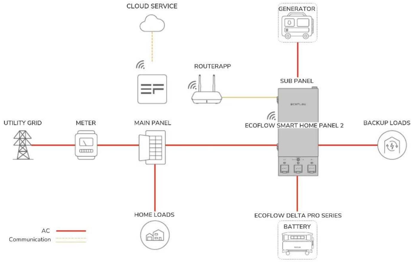
flowchart
graph TD
    A["UTILITY GRID"] --> B["METER"]
    B --> C["MAIN PANEL"]
    C --> D["HOME LOADS"]
    D --> E["ECOFLOW SMART HOME PANEL 2"]
    E --> F["BATTERY"]
    F --> G["ECOFLOW DELTA PRO SERIES"]
    G --> H["BACKUP LOADS"]
    I["CLOUD SERVICE"] --> J["云"]
    K["ROUTERAPP"] --> L["Routerapp"]
    M["GENERATOR"] --> N["SUB PANEL"]
    style A fill:#f9f,stroke:#333
    style B fill:#ccf,stroke:#333
    style C fill:#cfc,stroke:#333
    style D fill:#fcc,stroke:#333
    style E fill:#cff,stroke:#333
    style F fill:#ffc,stroke:#333
    style G fill:#cfc,stroke:#333
    style H fill:#fcc,stroke:#333
    style I fill:#fff,stroke:#333
    style J fill:#fff,stroke:#333
    style K fill:#fff,stroke:#333
    style L fill:#fff,stroke:#333
    style M fill:#fff,stroke:#333
    style N fill:#fff,stroke:#333
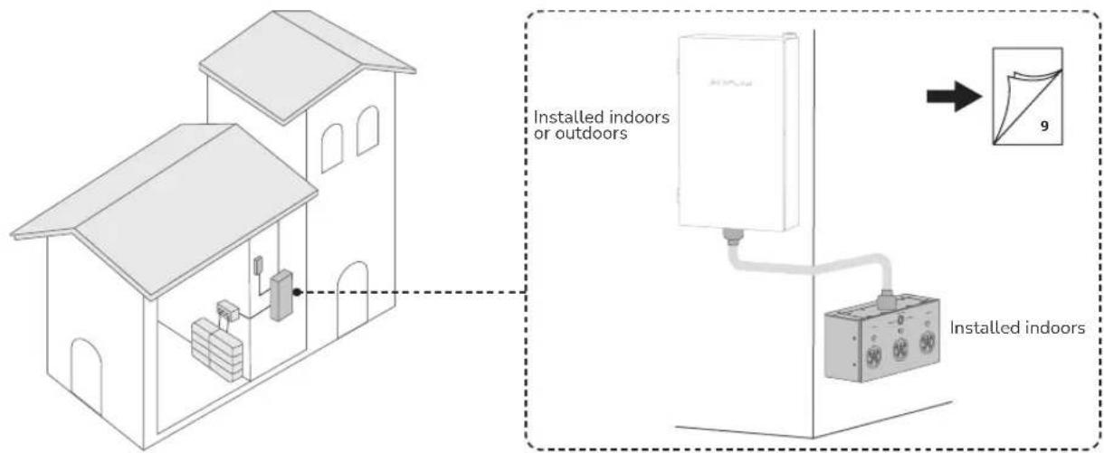
Installation
Scenarios
- Install the entire SHP2 indoors
NOTICE
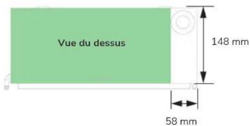
- Ensure that the glass door may swing open to 90^ .
Minimum clearance: 3 in. above, 21.7 in. - 52 in. below, 1.5 in. for the left side, and 3 ft for front clearance.
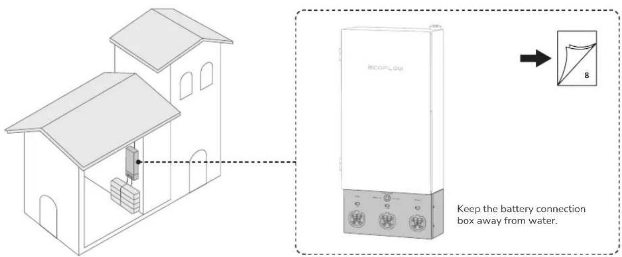
- Install the panel and the battery connection box individually
WARNING
- The battery connection box is not waterproof. Therefore, it should be installed indoors to avoid water.
- Ensure that the glass door may swing open to 90^ .
Minimum clearance for the distribution panel: 3 in. above and below, 3 ft for front clearance, 1.5 in. for the left side Minimum clearance for the battery connection box: 3 in. above, 21.7 in. - 52 in. below
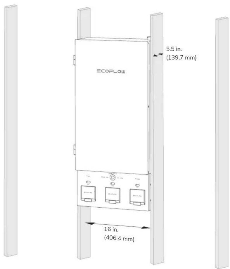
Mounting Options
Surface mounting and flush mounting are supported. Flush-mounting is shown below.
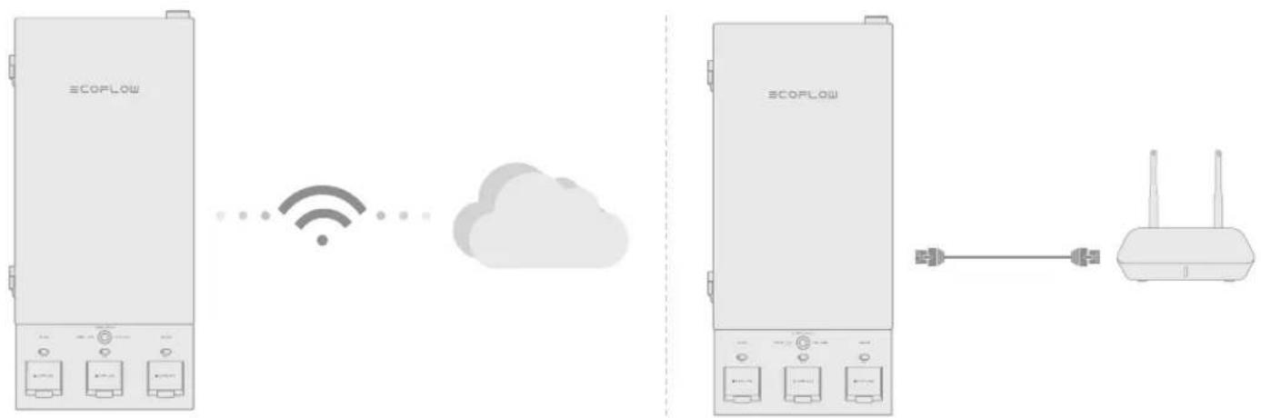
Internet Access
EN
You can use Wi-Fi or wired connection to access Internet.
Identify the location of the router and decide whether to use a wireless or wired connection.
For wired connection, prepare a CAT6, T568B straight-through cable, and set the corresponding cable entry.
flowchart
graph LR
    A["ECOPLOW"] -->|Wireless Signal| B["Cloud"]
    B --> C["Router"]
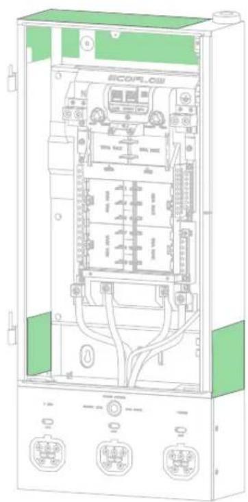
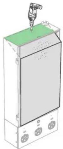
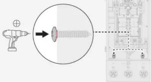
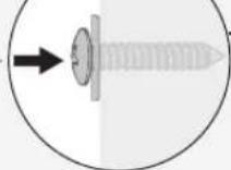
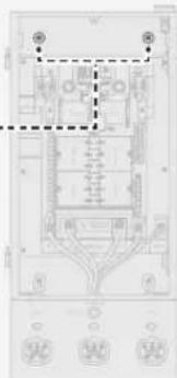
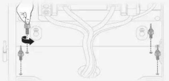
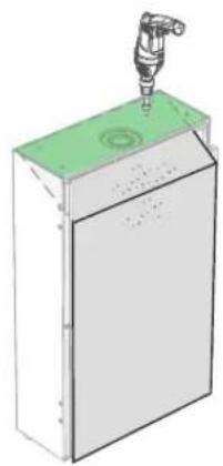
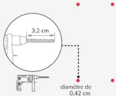
Choosing Cable Entry
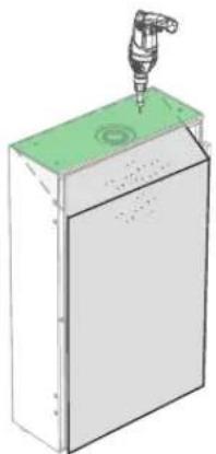
WARNING
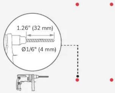
- Before drilling cable entry, cover the interior equipment to prevent debris from falling into the equipment, as shown in the 4 orientations below. If the device you receive is covered with protective firm, you can skip this step.
- Ensure that all the protective film has been fully removed after drilling. Otherwise, heat dissipation will be affected.
- Clear the debris after drilling to prevent interference with the equipment. A hydraulic hole puncher is recommended.
natural_image
Technical line drawing of an electrical enclosure with internal components and wiring (no readable text or symbols)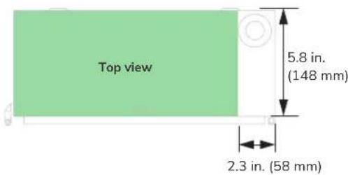
natural_image
3D diagram of a mechanical device with a central component and mounting holes (no text or symbols)Top

natural_image
3D diagram of a mechanical device with a lever and green base (no text or symbols)Bottom
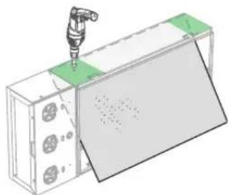
natural_image
3D diagram of a mechanical assembly with a tool inserted, showing a green component and a gray panel (no text or symbols)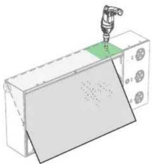
natural_image
3D illustration of a robotic arm operating on a device with a green indicator light (no text or symbols)RightLeft
1


2
3

(ST5.5×32) ×2
4


5
6

(ST5.5×32) ×2

×2
Scenario 2:
Installing the Panel and Battery Connection Box Individually
EN
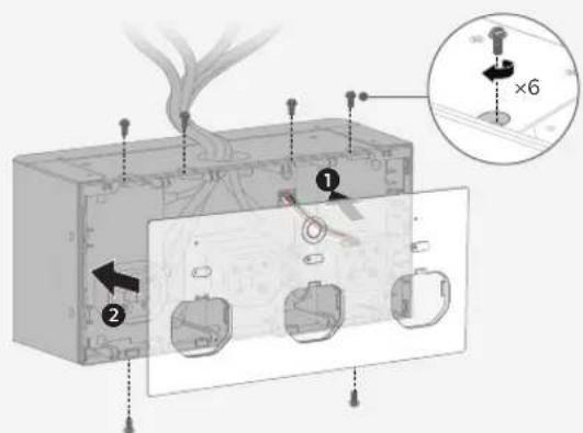
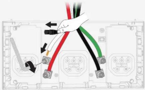
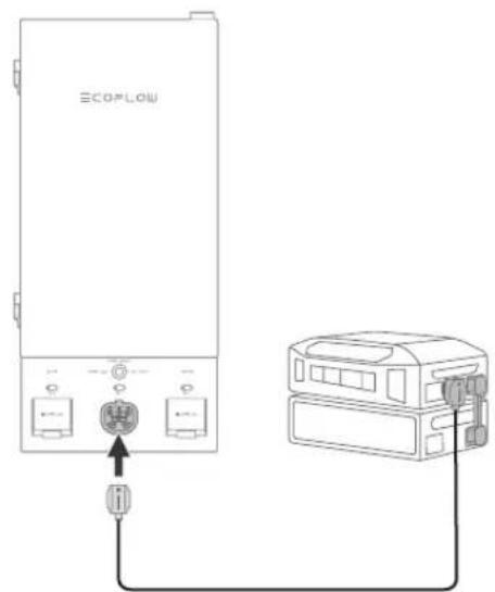
Step 1: Remove the battery connection box from the panel.
Step 2: Mount the panel on the wall.
Step 3: Mount the battery connection box on the wall.
- Removing the battery connection box
1
Loosen the nuts on backup lugs.
Disconnect the internal communication cable.
2
natural_image
Line drawing of a cable being inserted into a device (no text or symbols present)3
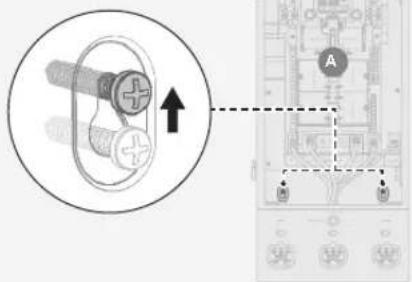
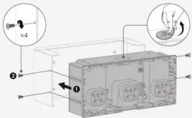
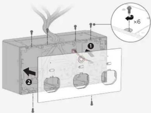
Remove the screws that secure the battery connection box, and take off the box.
natural_image
Diagram of a device with connected components and directional arrows, no readable text or symbols present- Mounting the panel and the battery connection box
NOTICE
- Make new 2-AWG power cables (N, L1, L2), 6-AWG for the GND cable, and a new shielded network cable, CAT6, T568B, ≤787 in. (20 m), for connection.
- Mounting the battery connection box upside down is not recommended.
- Torque value: 50 in-lbs (5.6 N·m) for 2 AWG, 45 in-lbs (5.1 N·m) for 6 AWG.
- Conduit fitting: 1-1/2 in.
To mount the panel, see "Scenario 1: Installing the Entire SHP2 Indoors" on page 8 for detailed steps.
Follow the steps on the next page to mount the battery connection box.
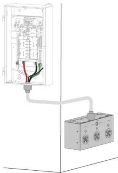
natural_image
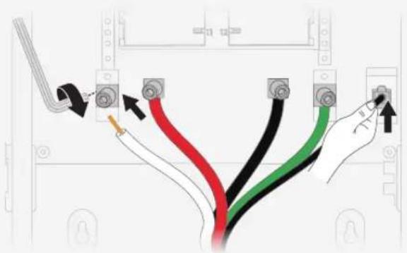
Diagram of an electrical enclosure connected to a terminal block, showing wiring and components (no text or labels)1
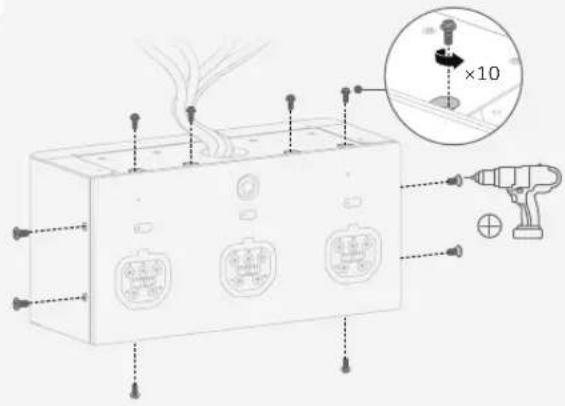
Unscrew the top, side, and bottom screws.
3
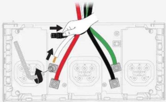
Loosen the screws on backup lugs, and unravel the internal COM cable.
5
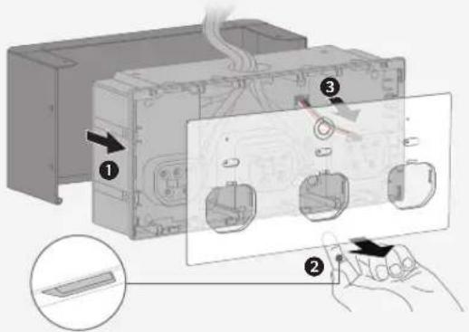
Install the battery connection box back to its enclosure.
Remove the protective pad before installing the conduit fitting.
7
Connect the other ends to the panel's matching lugs.
2
Take out the cover and remove the auxiliary power cable.
4
Mount the enclosure of battery connection box on the wall.
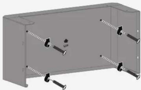
natural_image
3D diagram of a mechanical housing with multiple bolts and an 'UP' label (no text or symbols beyond the label)6
Make new power and COM cables. Connect their ends to the battery connection box's matching lugs.
8
Close the box.
Wiring
WARNING
- Risk of electric shock. Before wiring, make sure the power is off. Ensure that main and branch circuit breakers are in the OFF position.
• Install conduit fittings when wiring.
EN
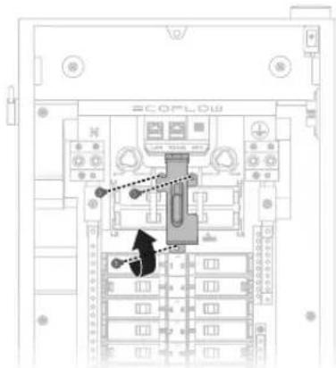
Removing the Interlock
The interlock has been pre-installed when shipped, so remove it before installing main circuit breakers.
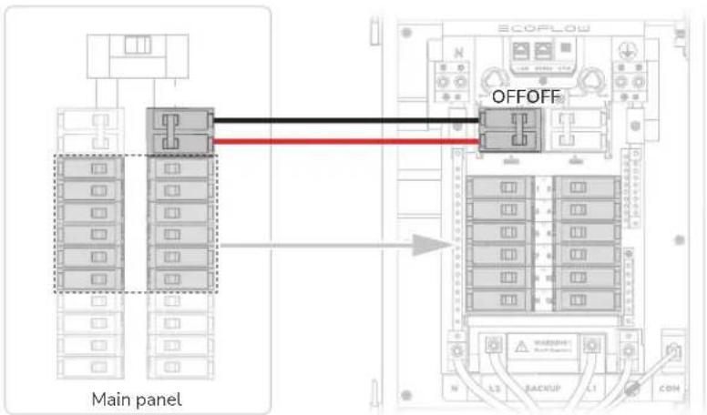
Installing Circuit Breakers
One 50A main circuit breaker for the generator (optional), two 100A for the grid (one installed in the branch breaker slot of the main panel, one installed in the main breaker slot of Smart Home Panel 2), to be purchased separately.
Branch circuit breaker: Max. 60A, 1 inch, AFCI/GFCI supported, relocated from the main panel
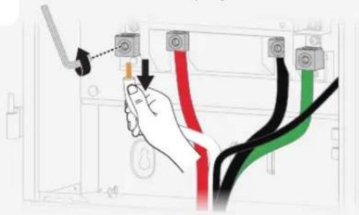
Connecting the Grid Conductors
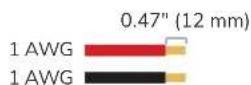

See instructions on breakers for torque value of hot wires

50 in-lbs (5.6 N·m) for 1 AWG 45 in-lbs (5.1 N·m) for 4 AWG
Connecting the Generator Conductors

See instructions on breakers for torque value of hot wires
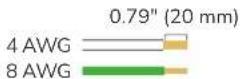

45 in-lbs (5.1 N·m) for 4 AWG 40 in-lbs (4.5 N·m) for 8 AWG
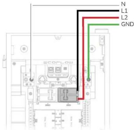
Connecting the Home Load Conductors


See instructions on breakers for torque value of hot wires

35 in-lbs (4.0 N·m) for 6-4 AWG 25 in-lbs (2.8 N·m) for 8 AWG 20 in-lbs (2.3 N·m) for 14-10 AWG
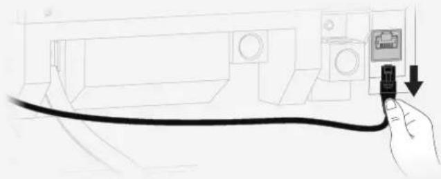
Connecting Communications Cables (If Needed)
For Ethernet connection, plug a CAT6, T568B straight-through cable to the Ethernet port.

Checking Connection
Before installing the defront cover and glass door, check the following connection items.
| No. Check Item | |
| 1 Confirm that all | connections are correct, properly grounded, and secure. |
| 2 Confirm that all | screws are tightened. |
| 3 Use a multimeter | in continuity setting to make sure that the hot wire is not short circuited to neutral. |
| 4 Use a multimeter | in continuity setting to make sure that the hot wire is not short circuited to ground. |
Installation
Installing the Interlock
Install the interlock onto the panel before installing the deadfront cover.
Installing the Deadfront Cover
Remove twist-outs for home loads. If you connect with a generator, remove the twist-out for the generator main circuit breaker. Fill any unused open spaces on the cover.
Installing the
Glass Door
Slide down the glass door onto the hinges.
Energizing

- Before energizing, ensure that main and branch circuit breakers are in the OFF position.
To energize, first turn ON the main breaker, and then turn ON each individual branch circuit breaker.
SHP2 starts self-test. Check the LED indicator, the grid indicator should be white and always on, the error indicator is off. please view the error description and eliminate it in the EcoFlow app.
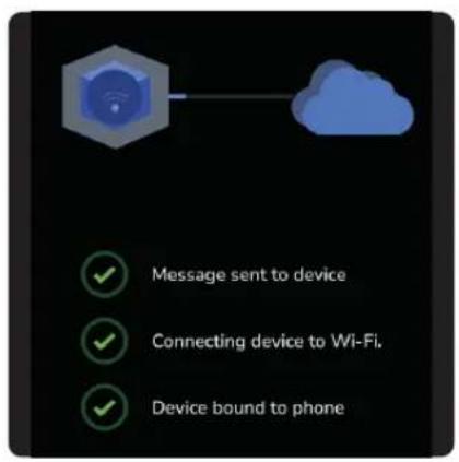
Internet and
Initialization Setup
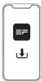
- Download the EcoFlow app.


- Pair the Smart Home Panel 2 with the EcoFlow app. 3. Follow instructions in the EcoFlow app to carry out system commissioning.
EN

| LED Indication
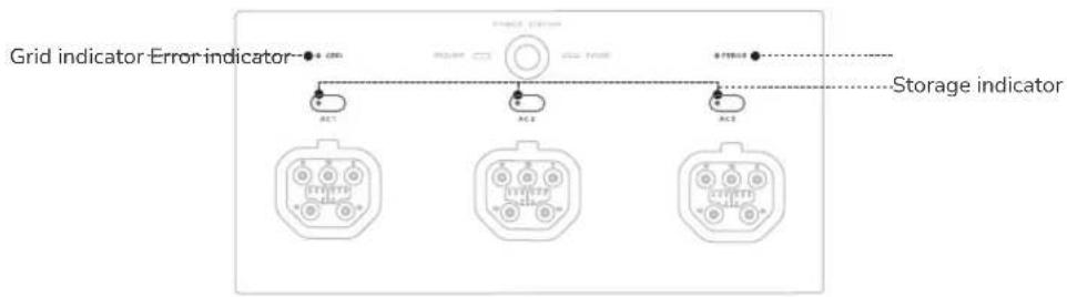
| Indicator Status Description | ||||
| Grid indicator | ○ | White Solid Power grid is on | ||
| ☀️ | Red and white Alternate blinking Power grid is faulty | |||
| ● | Red Solid Grid voltage is not detected | |||
| Storage indicator (AC1/AC2/AC3) | ● | Green | Solid Feeding electricity to loads | |
| ☀️ | Green | Breathing Standby | ||
| ● | Yellow Solid | Charging | ||
| ● | Red Solid | Error | ||
| Error indicator | ● | Dim Off No system error | ||
| ● | Red | Solid System error | ||
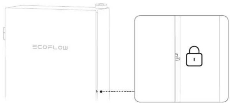
| Locking the Panel
Generator

- If the generator has a bonded neutral, you should remove the ground-neutral bond from the generator. Otherwise, GFCI/AFCI will malfunction.
Connecting a Generator
Install an inlet box between the generator and the panel.
To connect with a generator, see "Connecting the Generator Conductors".
To install the interlock, see "Installing the Interlock".
Remove the twin-out for generator main breaker.
Using Interlock
NOTICE
- After connecting the generator and turning on the power, it takes 25s for the house to get electricity.
Switch up for grid supply or switch down for generator supply.
When on grid supply, you can only turn on/off the main circuit breaker (grid).
When on generator supply, you can only turn on/off the main circuit breaker (generator).
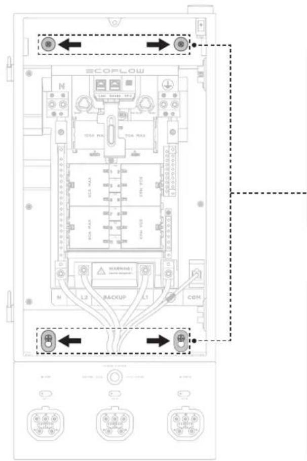
Manually Switching
Grid Supply And Backup
If you fail to switch between grid supply and backup power using the EcoFlow app, you can manually turn the both relay switching knobs in the distribution panel. However, only qualified electrical personnel should perform this manual switch.
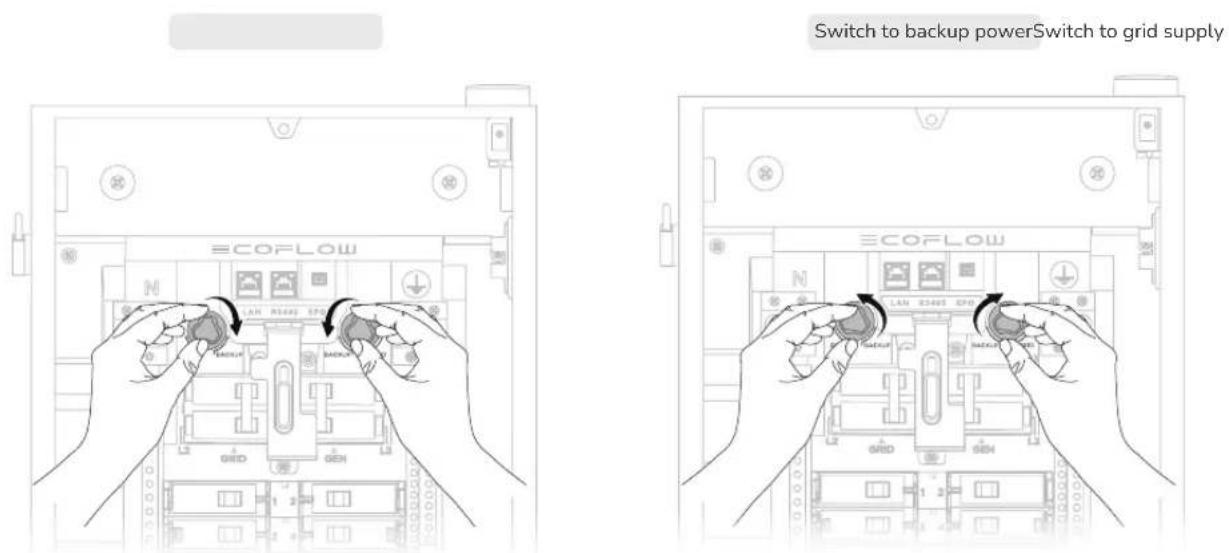

- Two knobs must be turned for switching.
NOTICE
- If you only connect 1 EcoFlow DELTA Pro, DELTA Pro will undergo charging, but not discharging.
- If you connect both EcoFlow DELTA Pro Ultra and DELTA Pro, both of them will undergo both charging and discharging.
- Refer to EcoFlow Smart Home Panel 2 Owner's Manual for more details: https://manuals.ecoflow.com/product/smart-home-panel-2
EN
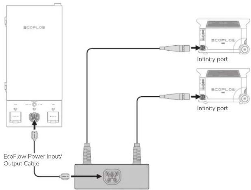
EcoFlow Power Input/Output Cable
For EcoFlow DELTA Pro (max. 2) For EcoFlow DELTA Pro Ultra (max. 3 units)
flowchart
graph TD
    A["ECOFlow"] --> B["EcoFlow Power Input/Output Cable"]
    B --> C["Device 1"]
    B --> D["Device 2"]
    C --> E["Infinity port 1"]
    D --> F["Infinity port 2"]
    E --> G["ECOFlow 1"]
    F --> H["ECOFlow 2"]
EcoFlow Double Voltage Hub - Power Input/Output Port (EcoFlow DELTA Pro)
Circuit Breaker
Compatibility
NOTICE
- EcoFlow Smart Home Panel 2 has been evaluated for use with the branch circuit breaker types listed below in accordance with the UL Standard for Panelboards.
Eaton
| Type Amp Catalog number Pole | |||
| General circuit breakers type BR 10-90 BR or BRH; followed by 110 to 290 | 1-pole and 2-pole | ||
| Duplex (tandem) circuit breakers type BD 10-50 BD followed by 1010 to 5050 1-pole | |||
| Quadplex (tandem) circuit breakers type BQ and BQC | 15-50 BQ followed by 215215 to 2502120 | 1-pole and 2-pole | |
| Combination arc fault circuit interrupter circuit breakers type BR | 10-20 | BRC, BRN or BRL followed by 110 to 120; followed by AF or CAF (pigtail only) | 1-pole and 2-pole |
| Ground fault circuit interrupter circuit breakers type GFTCB and GFEP | 10-60 | BRN, GFTCB, BRHN, or GFTCBH followed by 110 to 260; may be followed by GF (pigtail only) | 1-pole and 2-pole |
| Ground fault equipment protection circuit breakers type GFEP | 15-50 | BRN or GFEP followed by 115 to 250; may be followed by EP (pigtail only) | 1-pole and 2-pole |
| Dual function combination ground fault and arc-fault protection circuit breakers type BR | 10-20 | BRN or BRAFGF followed by 110 to 120; may be followed by DF (pigtail only) | 1-pole |
Square D
| Type Amp Catalog number Pole | |||
| General circuit breakers type HOM 10-90 HOM followed by 1 | 10 to 290 | 1-pole and 2-pole | |
| Tandem circuit breakers type HOMT | 10-30 | HOMT followed by 1010 to 3020 | 1-pole |
| Quad tandem circuit breakers type HOMT | 15-50 | HOMT followed by 1515215 to 2020250 | 1-pole and 2-pole |
| Quad tandem circuit breakers type HOMT | 15-50 | followed by 110 to 220; may be followed by P; followed by CAFI | 2-pole |
| Combination arc-fault circuit interrupter circuit breakers type HOM-CAFI | 10-20 | HOM followed by 110 to 220; may be followed by P; followed by CAFI (pigtail only) | 1-pole and 2-pole |
| Ground fault circuit interrupter circuit breakers type HOM-GFI | 10-50 | HOM followed by 110 to 250; may be followed by P; followed by GFI (pigtail only) | 1-pole and 2-pole |
| Ground fault equipment protection circuit breakers type HOM-EPD | 15-50 | HOM followed by 115 to 250; followed by EPD (pigtail only) | 1-pole and 2-pole |
| Dual function combination ground fault and arc-fault protection circuit breakers type HOM-DF | 10-20 | HOM followed by 110 to 120; may be followed by P; followed by DF (pigtail only) | 1-pole |
Siemens
| Type Amp Catalog number Pole | |||
| General circuit breakers type QP 10-90 | Q followed by 110 to 290; may be followed by H | 1-pole and 2-pole | |
| Duplex (tandem) circuit breakers type QT 10-30 | Q followed by 1010 to 3030 may be followed by NC | 1-pole | |
| Triplex (tandem) circuit breakers type QT 10-30 Q followed by 2 | 1010 to 23030; followed by CT | 1-pole and 2-pole | |
| Quadplex (tandem) circuit breakers type QT 15-40 | Q followed by 21515 to 24040; followed by CT2 | 2-pole | |
| Branch-feeder arc-fault circuit interrupter circuit breakers type QAF2 | 15-20 | QA followed by 115 to 120; followed by AF; may be followed by H (pigtail only) | 1-pole and 2-pole |
| Combination arc-fault circuit interrupter circuit breakers type QAF and QAF2 | 10-20 | Q or QA followed by 115 to 120; followed by AFC; may be followed by H (pigtail only) | 1-pole and 2-pole |
| Tandem combination arc-fault circuit interrupter circuit breakers type CAFCI | 10-20 | Q followed by 1010 to 2020; followed by AFC (pigtail only) | 1-pole |
| Ground fault circuit interrupter circuit breakers type QPF and QPF2 | 10-60 | QF followed by 110 to 260; followed by A; may be followed by H (pigtail only) | 1-pole and 2-pole |
| Ground fault equipment protection circuit breakers type QE | 15-60 | QE followed by 115 to 260; may be followed by H (pigtail only) | 1-pole and 2-pole |
| Dual function combination ground fault and arc-fault protection circuit breakers type QFGA2 | 10-20 | Q followed by 110 to 120; followed by DF; may be followed by H (pigtail only) | 1-pole |
GE
| Type Amp Catalog number Pole | |||
| General circuit breakers type THQL 15-70 THQL followed by 115 to 170; | 1-pole and 2-pole | ||
| Ground fault circuit interrupter circuit breakers type THQL | 15-20 Followed by GF (pigtail only) | 1-pole and 2-pole | |
| Branch-feeder arc-fault circuit interrupter circuit breakers type THQL | 15-30 Followed by AF (pigtail only) | 1-pole and 2-pole | |
Consignes
de sécurité
Avertissement
natural_image
Interior view of an open electrical enclosure with visible wiring and switches (no text or labels)natural_image
3D diagram of a mechanical device with a tool inserted into a green top panel, showing internal components and mounting holes (no text or symbols)Dessus
natural_image
3D diagram of a mechanical device with a lever and green base (no text or symbols)Fond
natural_image
3D diagram of a mechanical assembly with a precision tool inserted into a housing, showing internal components and a grid pattern (no text or symbols)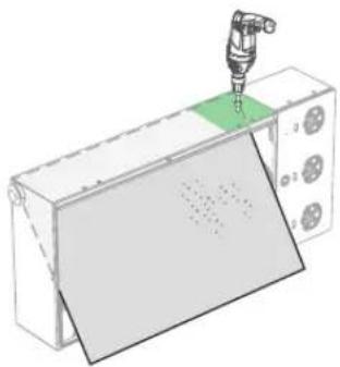
natural_image
3D illustration of a mechanical assembly with a tool inserted into a green component, no text or symbols presentDroitGauche
2
5
6

(ST5,5×32) ×2

×2
Scénario 2 :
natural_image
Illustration of a hand connecting electrical connectors to a device (no text or symbols visible)natural_image
Line drawing of a cable being inserted into an electronic device (no text or symbols)natural_image
Technical line drawing of a mechanical assembly with no visible text or symbolsnatural_image
Diagram of an electrical enclosure connected to a terminal block, showing wiring and components (no text or labels)7
natural_image
3D diagram of a mechanical housing with multiple hanging components and an 'UP' label (no text or symbols beyond the label)8
Fermez le boîtier.