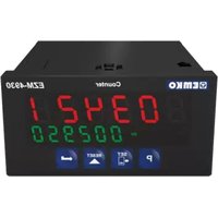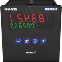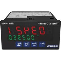
EZM-4950 - Programmable meter Emko - Free user manual and instructions
Find the device manual for free EZM-4950 Emko in PDF.


User questions about EZM-4950 Emko
0 question about this device. Answer the ones you know or ask your own.
Ask a new question about this device
Download the instructions for your Programmable meter in PDF format for free! Find your manual EZM-4950 - Emko and take your electronic device back in hand. On this page are published all the documents necessary for the use of your device. EZM-4950 by Emko.
USER MANUAL EZM-4950 Emko
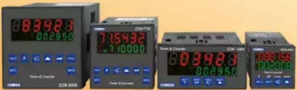
EZM-4450,EZM-4950,EZM-7750,EZM-9950 Programmable Timers & Counters
text_image
EZW-8350 EZW-4350 EZW-2008 EZW-1756 EZW-8350 EZW-4350 EZW-2008 EZW-1756 EZW-8350 EZW-4350 EZW-2008 EZW-1756 EZW-8350 EZW-4350 EZW-2008 EZW-1756 EZW-0950 EZW-0950 EZW-0950 EZW-0950 EZW-0950 EZW-0950 EZW-0950 EZW-0950 EZW-0950 EZW-0950 EZW-0950 EZW-0950 EZW-0950 EZW 1756 EZW 1756 EZW 1756 EZW 1756 EZW 1756 EZW 1756 EZW 1756 EZW 1756 EZW 1756 EZW 1756 EZW 1756 EZW 1756 EZW 1756 EZW - 1756 EZW - 1756 EZW - 1756 EZW - 1756 EZW - 1756 EZW - 1756 EZW - 1756 EZW - 1756 EZW - 1756 EZW - 1756 EZW - 1756 EZW -1756 EZW -1756 EZW -1756 EZW -1756 EZW -1756 EZW -1756 EZW -1756 EZW -1756 EZW -1756 EZW -1756 EZW -1756 EZW -1756 EZW -1754 EZW -1754 EZW -1754 EZW -1754 EZW -1754 EZW -1754 EZW -1754 EZW -1754 EZW -1754 EZW -1754 EZW -1754 EZW -1754 EZW -1754 EZW 1754 EZW 1754 EZW 1754 EZW 1754 EZW 1754 EZW 1754 EZW 1754 EZW 1754 EZW 1754 EZW 1754 EZW 1754 EZW 1754 EZW 1753 EZW 1753 EZW 1753 EZW 1753 EZW 1753 EZW 1753 EZW 1753 EZW 1753 EZW 1753 EZW 1753 EZW 1753 EZW 1753 EZW 1753 EZW - 1753 EZW - 1753 EZW - 1753 EZW - 1753 EZW - 1753 EZW - 1753 EZW - 1753 EZW - 1753 EZW - 1753 EZW - 1753 EZW - 1753cRus CE UK CA EAC
EZM-4450,EZM-4950,EZM-7750,EZM-9950 Universal Input Programmable Timer & Counter with Output Module System
- 6 digits Process (PV) and 6 digits Set (SV) Value Display
- Operation with 2 Set Values
- Reset, Pause and ChA-ChB Counting Inputs
- NPN/PNP input type selection
- Configurable Counter/Totalizer Counter, Batch Counter, Timer, Chronometer, Frequencymeter and Tachometer Functions
-Programmable Time Bases for Timer and Chronometer (Second, Minute, Hour) - Operation with Automatic and Manual Reset
- Output Module System
- INC,DEC,INC/INC,INC/DEC,UP/DOWN, x1 / x2 / x4Counting with Phase Shifting Property in Counter Function
- Multiplication Coefficient and Decimal Point Position
-Different Alarm Alternatives in Frequencymeter and Cycle Measuring Functions - Absolute or Offset Operation in Counter Function
- RS-232 (standard) or RS-485 (optional) Serial Communication with Modbus ASCII or RTU Protocol
SPECIFICATIONS:
INPUT :
Counting Inputs (Ch-A, Ch-B): Switch, Proximity, Capacitive sensor or encoder can be connected.
Reset Input: Switch, Proximity or Capacitive sensor can be connected.
Pause Input: Switch, Proximity or Capacitive sensor can be connected.
Input Type Selection: It can be selected NPN/PNP with DIP Switch that is located on the device.
Reset Function: Automatic or Manual.
Count Input Types:
INC,DEC,INC/INC,INC/DEC,UP/DOWN ,x1 / x2 / x4: (PfaserStudlerg)
counting
OUTPUT
Output Modules : There are two module sockets for plugging the output modules.
- Relay Output Module
- SSR Output Module (Max. 26mA, 22V==)
- Digital (Transistor) Output Module (Max.40mA@18V)
SUPPLY VOLTAGE
Supply Voltage :
100-240 V ∼ 50/60 Hz (-15%; +10%) -6VA
24V ∼ 50/60 Hz (-15% ; +10%) -6VA
24V = (15%; +10%) -6W
(Must be determined in order.)
DISPLAY
Actual Count Value Display :
EZM-4450 : 8 mm Red 6 digit LED Display
EZM-4950 : 13.2 mm Red 6 digit LED Display
EZM-7750 : 10.8 mm Red 6 digit LED Display
EZM-9950 : 13.2 mm Red 6 digit LED Display
Set Value Display
EZM-4450 : 8 mm Green 6 digit LED Display
EZM-4950 : 8 mm Green 6 digit LED Display
EZM-7750 : 8 mm Green 6 digit LED Display
EZM-9950 : 8 mm Green 6 digit LED Display
LEDs: S1(Set1 value), S2(Set2 value), O1/2(Output Status) LEDs.
ENVIRONMENTAL RATINGS and PHYSICAL SPECIFICATIONS Operating
Temperature 0...50°C
Humidity none condensing
Protection Class IP65 at Front, IP20 at rear.
Mounting: Type-1 Enclosure Mounting
Installation: Fixed installation Category II
Over Voltage Category: II
Pollution Degree: II, office or workplace, none conductive pollution
Weight
DIP SWITCH Adjustment
Function Selection
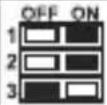 | Counter / Totalizer Counter |
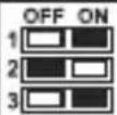 | Batch Counter |
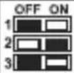 | Timer |
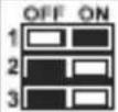 | Frequencymeter / Tachometer |
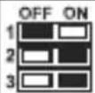 | Chronometer |
Input Type Selection
| OFF ON4 | NPN |
| OFF ON4 | PNP |
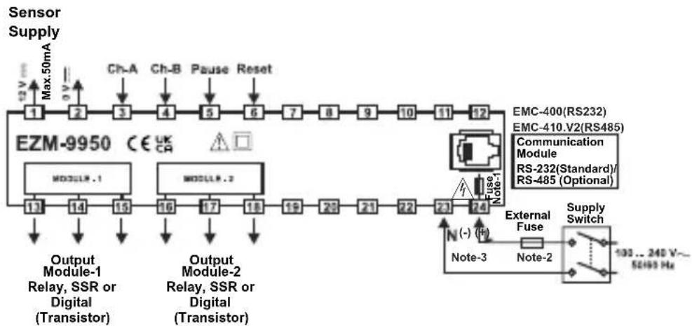
Electrical Wirings
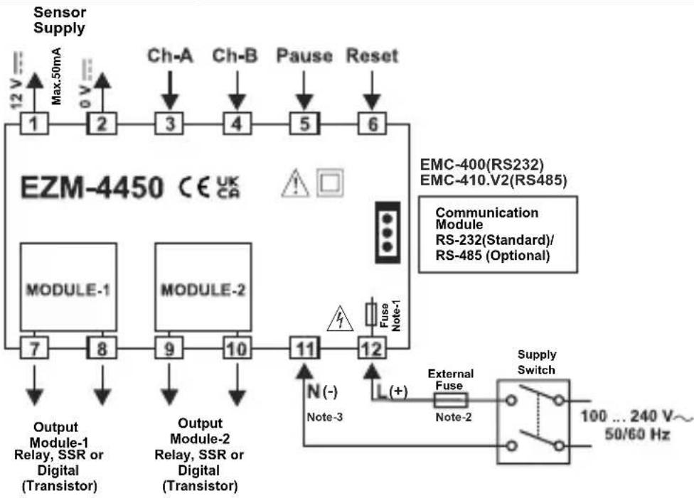
flowchart
graph TD
    A["Sensor Supply"] --> B["1"]
    B --> C["2"]
    C --> D["3"]
    D --> E["4"]
    E --> F["5"]
    F --> G["6"]
    H["EZM-4450 CE UK CA"] --> I["MODULE-1"]
    H --> J["MODULE-2"]
    H --> K["Output Module-1 Relay, SSR or Digital (Transistor)"]
    H --> L["Output Module-2 Relay, SSR or Digital (Transistor)"]
    H --> M["External Fuse"]
    M --> N["Supply Switch"]
    N --> O["100 ... 240 V~ 50/60 Hz"]
    P["Ch-A"] --> Q["3"]
    R["Ch-B"] --> S["4"]
    T["Pause"] --> U["5"]
    V["Reset"] --> W["6"]
    X["Fuse Note-1"] --> Y["11"]
    Z["N(-)"] --> AA["Note-3"]
    AB["L(+)"] --> AC["Note-2"]
    AD["EMC-400(RS232) EMC-410.V2(RS485)"] --> AE["Communication Module RS-232(Standard)/RS-485 (Optional)"]
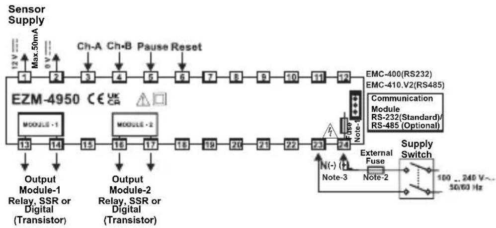
flowchart
graph TD
    A["Sensor Supply"] --> B["1"]
    B --> C["2"]
    C --> D["3"]
    D --> E["4"]
    E --> F["5"]
    F --> G["6"]
    G --> H["7"]
    H --> I["8"]
    I --> J["9"]
    J --> K["10"]
    K --> L["11"]
    L --> M["12"]
    M --> N["EMC-400(RS232)"]
    M --> O["EMC-410.V2(RS485)"]
    P["Ch-A Ch-B Pause Reset"] --> Q["EZM-4950 CE UK CR"]
    R["MODULE 1"] --> S["13"]
    T["MODULE 2"] --> U["14"]
    V["Output Module-1 Relay, SSR or Digital (Transistor)"] --> W["15"]
    X["Output Module-2 Relay, SSR or Digital (Transistor)"] --> Y["16"]
    Z["Output Module-2 Relay, SSR or Digital (Transistor)"] --> AA["17"]
    AB["External Fuse Note-1"] --> AC["23"]
    AD["External Fuse Note-2"] --> AE["24"]
    AF["External Fuse Note-3"] --> AG["N(-) (-)"]
    AH["External Fuse Note-2"] --> AI["Note-3"]
    AJ["External Fuse Note-2"] --> AK["Supply Switch 100 ... 240 V~ 50/60 Hz"]
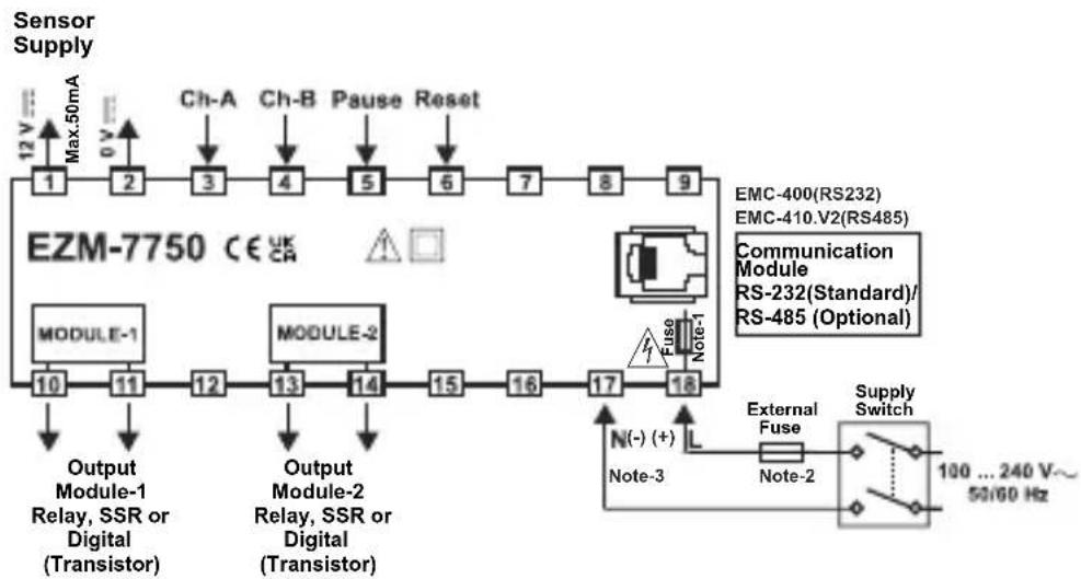
flowchart
graph TD
    A["Sensor Supply"] --> B["Ch-A"]
    A --> C["Ch-B"]
    A --> D["Pause"]
    A --> E["Reset"]
    B --> F["1"]
    C --> G["2"]
    D --> H["3"]
    E --> I["4"]
    F --> J["6"]
    G --> K["7"]
    H --> L["8"]
    I --> M["9"]
    J --> N["EMC-400(RS232)"]
    J --> O["EMC-410.V2(RS485)"]
    J --> P["Communication Module"]
    P --> Q["RS-232(Standard)/RS-485 (Optional)"]
    R["EZM-7750 CE UK CA"] --> S["MODULE-1"]
    R --> T["MODULE-2"]
    U["Output Module-1 Relay, SSR or Digital (Transistor)"] --> V["10"]
    U --> W["11"]
    X["Output Module-2 Relay, SSR or Digital (Transistor)"] --> Y["13"]
    X --> Z["14"]
    AA["External Fuse"] --> AB["Note-3"]
    AC["External Fuse"] --> AD["Note-2"]
    AE["External Fuse"] --> AF["Supply Switch"]
    AG["N(-) (+)"] --> AH["L"]
    AI["Note-1"] --> AJ["Fuse"]
    AK["Note-1"] --> AL["External Fuse"]
    AM["100 ... 240 V~ 50/60 Hz"] --> AN["Supply Switch"]
flowchart
graph TD
    A["Sensor Supply"] --> B["EZM-9950 CE UK CR"]
    B --> C["Ch-A"]
    B --> D["Ch-B"]
    B --> E["Pause"]
    B --> F["Reset"]
    B --> G["Max.50mA"]
    B --> H["Ch-A"]
    B --> I["Ch-B"]
    B --> J["Pause"]
    B --> K["Reset"]
    B --> L["Ch-A"]
    B --> M["Ch-B"]
    B --> N["Pause"]
    B --> O["Reset"]
    P["Output Module-1 Relay, SSR or Digital (Transistor)"] --> Q["MODULE-1"]
    R["Output Module-2 Relay, SSR or Digital (Transistor)"] --> S["MODULE-2"]
    T["Fuse Note-1"] --> U["EMC-400(RS232)"]
    T --> V["EMC-410.V2(RS485)"]
    T --> W["Communication Module RS-232(Standard)/RS-485 (Optional)"]
    X["External Fuse"] --> Y["Supply Switch"]
    Z["Note-3"] --> AA["(-) (F)"]
    AB["Note-2"] --> AC["Note-3"]
    AD["103... 240 V~ 52493 Hz"] --> AE["Supply Switch"]
Note-1 : There is an internal fusible flameproof resistor.
Note-2 : External fuse is recommended.
1A00.T for power supply 240 V\~ or 24V\~
1A—T for power supply 24V ---
Note-3: "L" is (+), "N" is (-) for 24V—supply voltage
DIMENSIONS
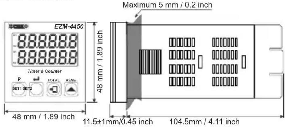
text_image
EZM-4450 888888 888888 Timer & Counter P SET1 SET2 TOTAL RESET 48 mm / 1.89 inch 48 mm / 1.89 inch Maximum 5 mm / 0.2 inch 11.5±1mm/0.45 inch 104.5mm / 4.11 inch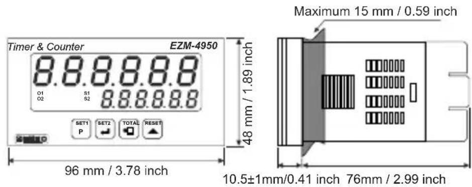
text_image
Timer & Counter EZM-4950 8.8.8.8.8.8 O1 S1 O2 S2 8.8.8.8.8 SET1 SET2 TOTAL RESET P 48 mm / 1.89 inch 96 mm / 3.78 inch Maximum 15 mm / 0.59 inch 10.5±1mm/0.41 inch 76mm / 2.99 inch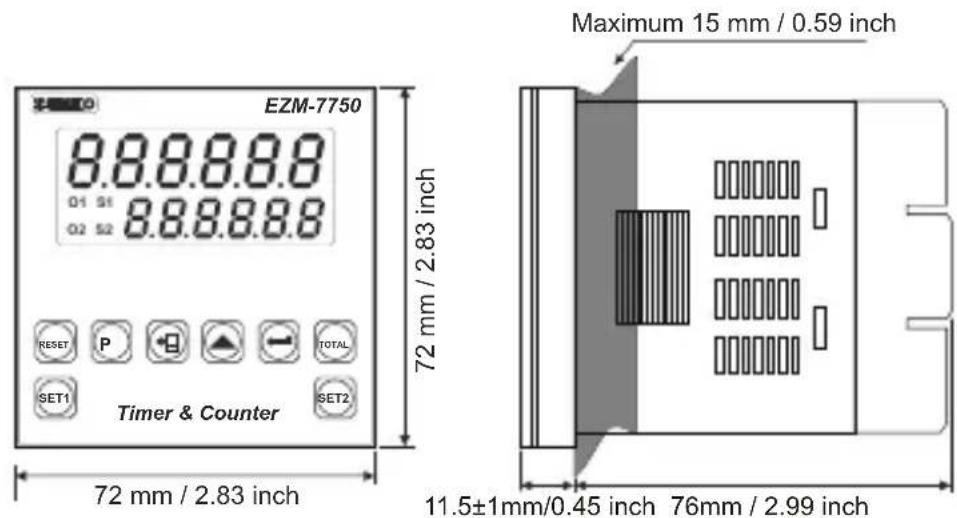
text_image
EZM-7750 8.8.8.8.8 O1 S1 O2 S2 8.8.8.8.8 72 mm / 2.83 inch Timer & Counter RESET P TOTAL SET1 SET2 72 mm / 2.83 inch Maximum 15 mm / 0.59 inch 11.5±1mm/0.45 inch 76mm / 2.99 inch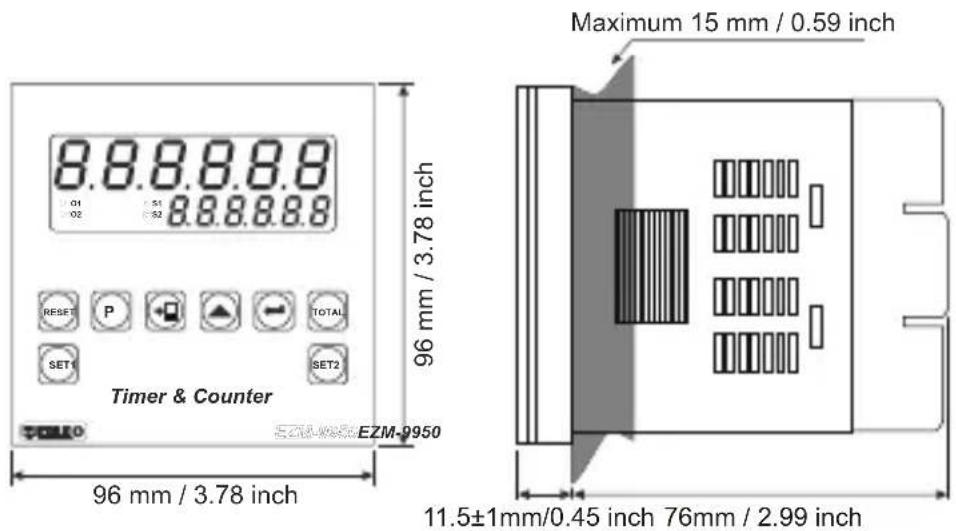
text_image
8.8.8.8.8 01 51 02 8.8.8.8.8 96 mm / 3.78 inch Timer & Counter EZM-9950 96 mm / 3.78 inch Maximum 15 mm / 0.59 inch 11.5±1mm/0.45 inch 76mm / 2.99 inchPANEL MOUNTING
text_image
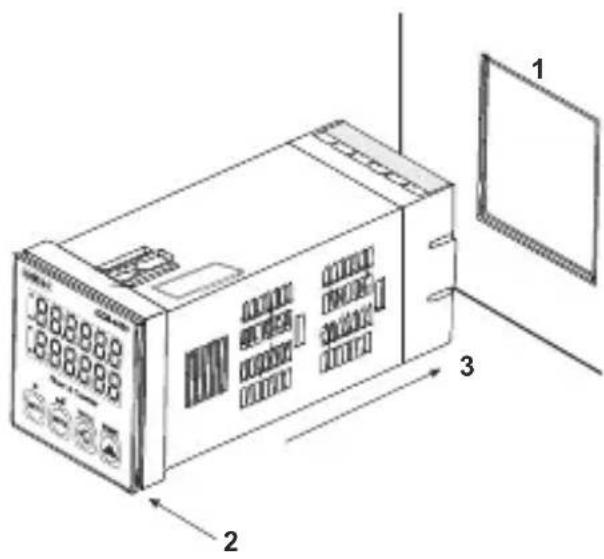
Technical diagram of a microwave oven with labeled parts 1, 2, and 3 showing internal components and ventilation slots.1- Before mounting the device in your panel, makesure that the panel cut-out is suitable.
2- Check front panel gasket Position.
3- Insert the device through the cut-out. If the mounting clamp are on the unit, put out them before inserting the unit to the panel.
text_image
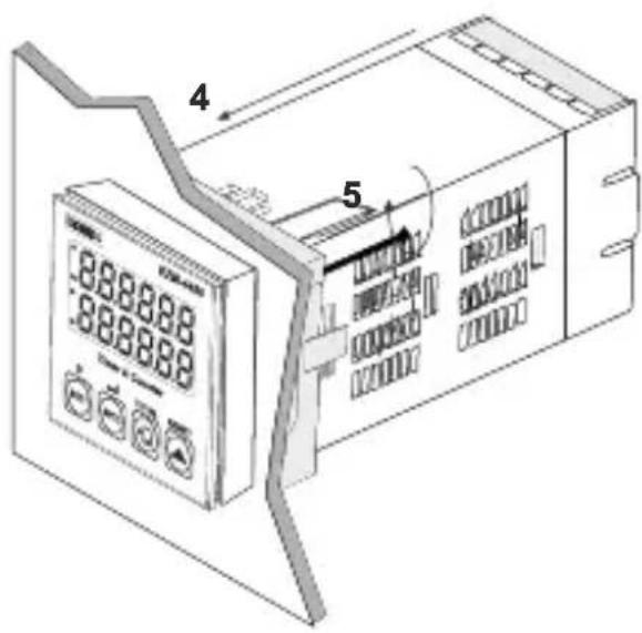
888888 888888 4 54-Insert the unit in the panel cut-out from the front side.
5-Insert the mounting clamps to the holes that located top and bottom sides of device and screw up the fixing screws until the unit completely immobile within the panel.
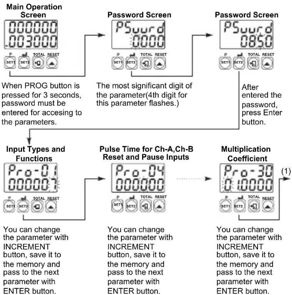
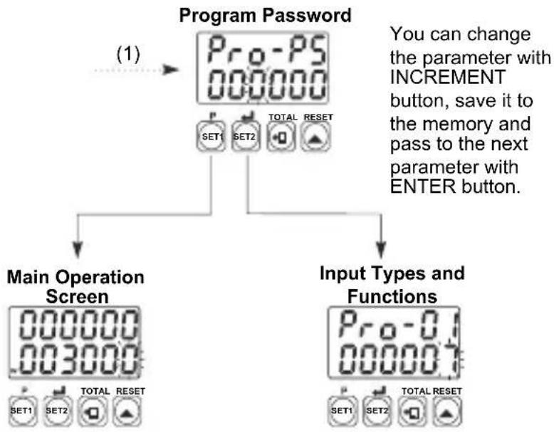
Accessing to the Program Parameters
flowchart
graph TD
    A["Main Operation Screen"] --> B["Password Screen"]
    B --> C["Password Screen"]
    C --> D["Input Types and Functions"]
    D --> E["Pulse Time for Ch-A,Ch-B Reset and Pause Inputs"]
    E --> F["Multiplication Coefficient"]
    F --> G["(1)"]

    subgraph Input Types and Functions
        H["Pro-01 000007 SET1 SET2 TOTAL RESET"]
    end

    I["When PROG button is pressed for 3 seconds, password must be entered for accessing to the parameters."] --> B
    J["The most significant digit of the parameter(4th digit for this parameter flashes.)"] --> B
    K["After entered the password, press Enter button."] --> C
    L["You can change the parameter with INCREMENT button, save it to the memory and pass to the next parameter with ENTER button."] --> D
    M["You can change the parameter with INCREMENT button, save it to the memory and pass to the next parameter with ENTER button."] --> E
    N["You can change the parameter with INCREMENT button, save it to the memory and pass to the next parameter with ENTER button."] --> F
flowchart
graph TD
    A["Program Password"] --> B["Main Operation Screen"]
    A --> C["Input Types and Functions"]
    B --> D["SET1 SET2 TOTAL RESET"]
    C --> E["SET1 SET2 TOTAL RESET"]
    F["SET1 SET2 TOTAL RESET"] --> G["SET1 SET2 TOTAL RESET"]
    H["SET1 SET2 TOTAL RESET"] --> I["SET1 SET2 TOTAL RESET"]
    J["SET1 SET2 TOTAL RESET"] --> K["SET1 SET2 TOTAL RESET"]
    L["SET1 SET2 TOTAL RESET"] --> M["SET1 SET2 TOTAL RESET"]
    N["SET1 SET2 TOTAL RESET"] --> O["SET1 SET2 TOTAL RESET"]
    P["SET1 SET2 TOTAL RESET"] --> Q["SET1 SET2 TOTAL RESET"]
    R["SET1 SET2 TOTAL RESET"] --> S["SET1 SET2 TOTAL RESET"]
    T["SET1 SET2 TOTAL RESET"] --> U["SET1 SET2 TOTAL RESET"]
    V["SET1 SET2 TOTAL RESET"] --> W["SET1 SET2 TOTAL RESET"]
    X["SET1 SET2 TOTAL RESET"] --> Y["SET1 SET2 TOTAL RESET"]
    Z["SET1 SET2 TOTAL RESET"] --> AA["SET1 SET2 TOTAL RESET"]
    AB["SET1 SET2 TOTAL RESET"] --> AC["SET1 SET2 TOTAL RESET"]
    AD["SET1 SET2 TOTAL RESET"] --> AE["SET1 SET2 TOTAL RESET"]
    AF["SET1 SET2 TOTAL RESET"] --> AG["SET1 SET2 TOTAL RESET"]
    AH["SET1 SET2 TOTAL RESET"] --> AI["SET1 SET2 TOTAL RESET"]
    AJ["SET1 SET2 TOTAL RESET"] --> AK["SET1 SET2 TOTAL RESET"]
    AL["SET1 SET2 TOTAL RESET"] --> AM["SET1 SET2 TOTAL RESET"]
    AN["SET1 SET2 TOTAL RESET"] --> AO["SET1 SET2 TOTAL RESET"]
    AP["SET1 SET2 TOTAL RESET"] --> AQ["SET1 SET2 TOTAL RESET"]
    AR["SET1 SET2 TOTAL RESET"] --> AS["SET1 SET2 TOTAL RESET"]
    AT["SET1 SET2 TOTAL RESET"] --> AU["SET1 SET2 TOTAL RESET"]
    AV["SET1 SET2 TOTAL RESET"] --> AW["SET1 SET2 TOTAL RESET"]
    AX["SET1 SET2 TOTAL RESET"] --> AY["SET1 SET2 TOTAL RESET"]
    AZ["SET1 SET2 TOTAL RESET"] --> BA["SET1 SET2 TOTAL RESET"]
    BB["SET1 SET2 TOTAL RESET"] --> BC["SET1 SET2 TOTAL RESET"]
    BD["SET1 SET2 TOTAL RESET"] --> BE["SET1 SET2 TOTAL RESET"]
    BF["SET1 SET2 TOTAL RESET"] --> BG["SET1 SET2 TOTAL RESET"]
    BH["SET1 SET2 TOTAL RESET"] --> BI["SET1 SET2 TOTAL RESET"]
    BJ["SET1 SET2 TOTAL RESET"] --> BK["SET1 SET2 TOTAL RESET"]
    BL["SET1 SET2 TOTAL RESET"] --> BM["SET1 SET2 TOTAL RESET"]
    BN["SET1 SET2 TOTAL RESET"] --> BO["SET1 SET2 TOTAL RESET"]
    BP["SET1 SET2 TOTAL RESET"] --> BQ["SET1 SET2 TOTAL RESET"]
    BR["SET1 SET2 TOTAL RESET"] --> BS["SET1 SET2 TOTAL RESET"]
    BT["SET1 SET2 TOTAL RESET"] --> BU["SET1 SET2 TOTAL RESET"]
    BV["SET1 SET2 TOTAL RESET"] --> BW["SET1 SET2 TOTAL RESET"]
    BX["SET1 SET2 TOTAL RESET"] --> BY["SET1 SET2 TOTAL RESET"]
    BZ["SET1 SET2 TOTAL RESET"] --> CA["SET1 SET2 TOTAL RESET"]
    CB["SET1 SET2 TOTAL RESET"] --> CC["SET1 SET2 TOTAL RESET"]
    DD["SET1 SET2 TOTAL RESET"] --> DE["SET1 SET2 TOTAL RESET"]
    BEZ["TOTAL RESET"] --> BEZ
Press PROG button to exit from programming selection without doing any changes.
Continue to press ENTER button for scanning all parameters.
Parameter Definitions
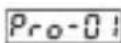
:Input Types and Functions
0 : Up(###) on rising edge of Ch-A input
1: Downco(DEC) rising edge of Ch-A input
2 :U,Count(INC,D)Edge of Ch-A input count on rising edge of Ch-B input
3 : Upcount on rising edge of Ch-A input, Upcount on rising edge of Ch-B input. (INC/INC)
4: Upcount on rising edge of Ch-A input when Ch-B is at 0 Downcount on rising edge of Ch-A when Ch-B is at .1(UP/DOWN)
5 : x1Ph(For Shiftingental Encoder )
6 : x2Ph(For Bioremental Encoder)
7 : x4Ph(For Bofingental Encoder)
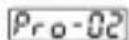
: Selection of Input Type Function for Chronometer
0 : Period measurement in Ch-A input
1 : Pulse time measurement in Ch-A input
2 Sum of the time difference between Ch-A and Ch-B inputs rising edges
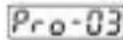
: Selection of Measuring Method
0 : Frequency or cycle is calculated by measuring cycle time of the signals in Ch-A input
1 : Frequency or cycle is calculated by counting the pulses in Ch-A input during the time is set in measurement period. Pro-08
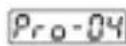
: Pulse Time of Ch-A, Ch-B, Reset and Pause Input
It is used to protect against the electrical contact debounce or the signal that is less than the determined pulse time.
It can be adjusted from 00000 to 000250 millisecond.

: Selection of Time Unit and Scale
200000 Hour / Minute It can be adjusted from . 0 to 99.59.
00000 : Minute It can be adjusted from / Second . 0 to 99.59.
200002 Second / millisecond. 0 to 99.99. It can be adjusted from
00000 Hour / Minute It can be adjusted from . 0 to 23.59.
It can be adjusted from 0 to 999.99.
It can be adjusted to 0 to 999.99.
It can be adjusted for 0 to 999.99.
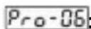
Output Functions
0: Manual Reset-1:
Device continues to count till manual reset is applied. When count value reaches the Set value, output position is changed.
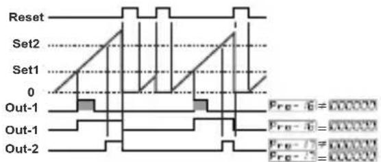
text_image
Reset Set2 Set1 0 Out-1 Out-1 Out-2 Pre - 6 = 000000 Pre - 6 = 000000 Pre - 7 = 000000 Pre - 7 = 0000001: Manual Reset-2:
Count value is added to total value when manual reset is active in COUNTER/TOTALIZER COUNTER functions.
2: Manual Reset-3:
Count value is added to total value when manual reset is active in COUNTER/TOTALIZER COUNTER functions.
3: Automatic Reset-1:
Count value is added to total value when manual reset is active in COUNTER/TOTALIZER COUNTER functions.
4: Automatic Reset-2:
Count value is added to total value when manual reset is active in COUNTER/TOTALIZER COUNTER functions.
5: Automatic Reset-3:
Count value is added to total value when manual reset is active in COUNTER/TOTALIZER COUNTER functions.

text_image
Reset Set2 Set1 0 Out-1 Out-1 Out-2 Pre-16 = Pre-17 Pre-16 = Pre-17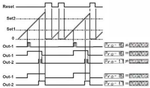
text_image
Reset Set2 Set1 0 Out-1 Out-1 Out-2 Out-1 Out-2 Pre-1B = 0.00000 Pre-1C = 0.00000 Pre-1D = 0.00000 Pre-1E = 0.00000 Pre-1F = 0.00000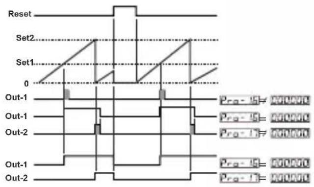
text_image
Reset Set2 Set1 0 Out-1 Out-1 Out-2 Out-1 Out-2 Pro-15 = MONO Pro-15 = MONO Pro-17 = MONO Pro-18 = MONO Pro-19 = MONO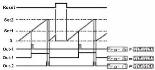
text_image
Reset Set2 Set1 0 Out-1 Out-1 Out-2 Pro-1a = 900000 Pro-1b = 900000 Pro-1c = 900000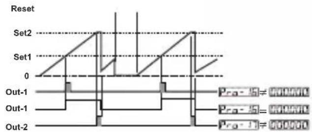
text_image
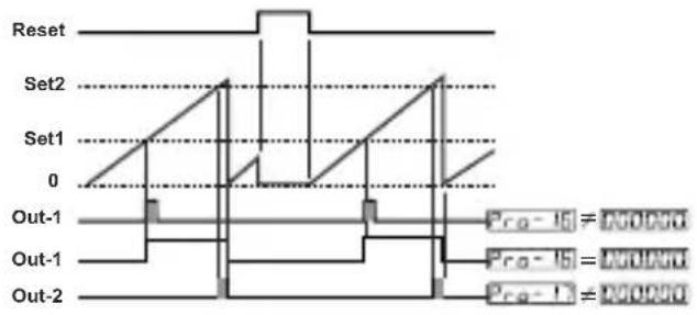
Reset Set2 Set1 0 Out-1 Out-1 Out-2 Prg-15 = 900000 Prg-16 = 900000 Prg-17 = 9000006:Automatic Reset-4:
Count value is added to total value when manual reset is active in COUNTER/TOTALIZER COUNTER functions.
text_image
Reset Set2 Set1 0 Out-1 Out-1 Out-2 Pro-15 = 0.0000 Pro-15 = 0.0000 Pro-1 = 0.00007: Automatic Reset-5:
Count value is added to total value when manual reset is active in COUNTER/TOTALIZER COUNTER functions.
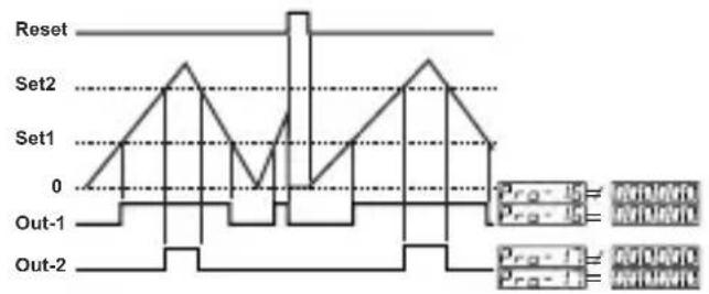
text_image
Reset Set2 Set1 0 Out-1 Out-2 Pro-1 Pro-2 Pro-3 Pro-4 Pro-5Pro-07: Input Signal Reset Time (Time Out)
Actual count value is reset if no signal is applied to Ch-A input for a time which is bigger than the value is set in this parameter.
It can be adjusted from 00000 to 000099 seconds.
Pro-08: Measurement Period
Number of pulses in Ch-A input is counted during this time.
It can be adjusted from 00000.1 to 000999 seconds.
Pro-09 : Output-1 Function
0 : O(ulpatching)ched
1 : Non-latched with hysteresis output is selected.
2 : Output-1 is an alarm output.
Pro-10 : Output-2 Function
0: O(ltatching) tched
1 : Non-latched with hysteresis output is selected.
Pro-11: Alarm Functions for Output-1
If Output-1 function parameter Pro-09 is selected alarm output, then Output-1 becomes active according to this parameter.
000000
High Alarm

flowchart
graph LR
    A["ON"] --> B["Set1Set1-Hys1"]
    C["OFF"] --> B
    B --> D["Output-1"]
000001
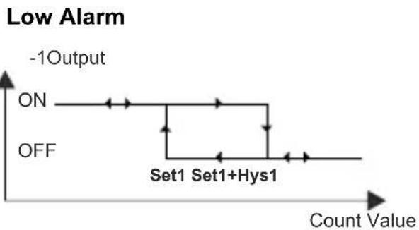
line
| Condition | Value | | ------------- | ----- | | ON | ON | | Off | OFF | | Set1 | Set1+Hys1 |000002
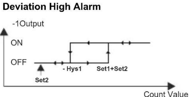
line
| Point | Count Value | | --------- | ----------- | | Set2 | Low | | - Hys1 | Medium | | Set1+Set2 | High |000003

line
| Deviation Band Alarm | Count Value | | --------------------- | ----------- | | ON | -1Output | | Off | -1Output | | Set2-Set1 | + Hys1 | | Set2 | + Hys1 |000004
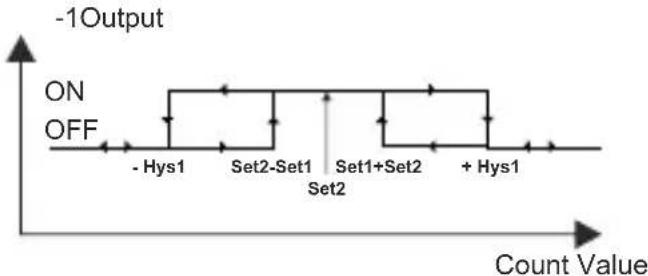
line
| Category | Value | | ------------ | ----- | | - Hys1 | ON | | Set2-Set1 | ON | | Set1+Set2 | ON | | + Hys1 | ON |Pro-12: Hysteresis for Output-1
Pro-13 : Hysteresis for Output-2
Pro-14 : Output-1 Operation Form
Output - 1 Normally De-energised.
000001 Output - 1 Normally Energised.
Pro-15 : Output-2 Operation Form
Output - 2 Normally De-energised.
000001 Output - 2 Normally Energised.
Pro-16 Output-1 Pulse Time
It determines how long Output-1 will be activated can be adjusted from 0000.00 to 0099.99 seconds.
Pro-17: Output-2 Pulse Time
It determines how long Output-2 will be active.10000.50 adjusted from 0099.99 seconds.
Pro-18: Start of the Controlling
Control is started when the unit is energised.
Control is started when count value reaches to SET1 value
Control is started when count value reaches to SET2 value
Pro-19: Direction of Counting
Upcount. ( 0 --> Preset )
000001 Downcount. ( Preset --> 0 )
Pro-20: Point position for the Display
No point.
00000 Between first and second digits.
000002 Between second and third digits.
000003 Between third and fourth digits.
000004 Between fourth and fifth digits.
Pro-21: Saving Count Value
Count value is saved to memory when power is disconnected and restored on power up.
Count value is not saved to memory when power is disconnected.
Pro-22: SET1 Operation Form Selection
000000 Absolute operation.SET1 can be adjusted from 900000 to 55556.
Operation with offset. SET1 can be defined ± Offset according to SET2 value.( SET1 = SET1 + SET2 )
Pro-23: Communication Accessing Address
Device address for serial communication bus. It can be adjusted from to 1000247.
Pro-24: Modbus Protocol Type Selection
000000 Modbus ASCII protocol is selected.
000001 Modbus RTU protocol is selected.
Pro-25: Communication Parity Selection
No Parity.
Odd Parity.
00002 Even Parity.
Pro-26: Communication Baud Rate
1200 Baud Rate
2400 Baud Rate
4800 Baud Rate
9600 Baud Rate
000004 19200 Baud Rate
Pro-27: Communication Stop Bit Selection
1 Stop Bit.
2 Stop Bits.
Pro-28: Reset and Set Protection (For Accessing from Front Panel)
No Reset and Set protection.
Only Reset button protection is active.
000002 SET1 and SET2 can not be changed.
Full Protection. Reset protection is active, also SET1 and SET2 can not be changed.
000004 SET1 can not be changed.
000005 SET2 can not be changed.
Pro-29: Frequency / Cycle Coefficient
It can be adjusted from 00000 to 000000. Count value is multiplied with this parameter.
Pro-30: Multiplication Coefficient
It can be adjusted from 0000 to 005999.
Pro-PS: Program Password
It is used for accessing to the program parameters.
It can be adjusted from 1000 to 10995.
If it is ; there is no password protection while entering to the program parameters.
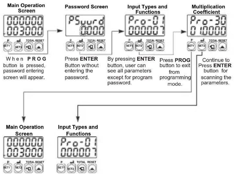
When programming prq button is pressed, will appear on the display. If this parameter is different from "0" and user wants to access to the program parameters;
1- If user does not enter the PSword value correctly; operation screen will appear without entering to operator parameters.
2- When PGward in top display and ONEXON in bottom display, if user presses ENTER button without entering password (for observing the parameters):
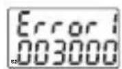
1- Position of the DIP Switch is wrong. (DIP Switch determines the operation function of the device and it is under the top cover.)
2- If the password is not 0, user can access to the parameters without entering the password and by pressing ENTER button.
flowchart
graph TD
    A["Main Operation Screen"] --> B["Password Screen"]
    B --> C["Input Types and Functions"]
    C --> D["Multiplication Coefficient"]
    D --> E["Main Operation Screen"]
    D --> F["Input Types and Functions"]
    E --> G["When P R O G button is pressed, password entering screen will appear."]
    F --> H["Press ENTER Button without entering the password."]
    F --> I["By pressing ENTER button, user can see all parameters except for program password."]
    F --> J["Press PROG button to exit from programming mode."]
    D --> K["Continue to Press ENTER button for scanning the parameters."]

3- If Actual Value is flashing and counting is stopped; It appears if any of the count value is bigger than the maximum count value.(Total count value for Counter/"Totalizer Counter"
Function - Batch count value for Batch Counter FUNCTION )
To remove this warning and reset the count value press RESET button.

4- If actual value is flashing and counting is not performed;
It appears if any of the count value is less than the minimum count value.
(Total count value for Counter/"Totalizer Counter" Function - Batch count value for Batch Counter FUNCTION) To remove this warning and reset the count value press RESET button.
Installation

Before beginning installation of this product, please read the instruction manual and warnings below carefully.
In package,
-One piece unit
-Two pieces mounting clamp
-One piece instruction manual
A visual inspection of this product for possible damage occurred during shipment is recommended before installation. It is your responsibility to ensure that qualified mechanical and electrical technicians install this product.
If there is danger of serious accident resulting from a failure or defect in this unit, power off the system and the electrical connection of the device from the system.
The unit is normally supplied without a power switch or a fuse. Use power switch and fuse as required.
Be sure to use the rated power supply voltage to protect the unit against damage and to prevent failure.
Keep the power off until all of the wiring is completed so that electric shock and trouble with the unit can be prevented.
Never attempt to disassemble, modify or repair this unit. Tampering with the unit may results in malfunction, electric shock or fire.
Do not use the unit in combustible or explosive gaseous atmospheres. During the equipment is putted in hole on the metal panel while mechanical installation some metal burrs can cause injury on hands, you must be careful.
Montage of the product on a system must be done with it's mounting clamp. Do not do the montage of the device with in appropriate mounting clamp. Be sure that device will not fall while doing the montage.
It is your responsibility if this equipment is used in a manner not specified in this instruction manual.
Warranty
EMKO Elektronik warrants that the equipment delivered is free from defects in material and workmanship. This warranty is provided for a period of two years. The warranty period starts from the delivery date.
This warranty is in force if duty and responsibilities which are determined in warranty document and instruction manual performs by the customer completely.
Maintenance
Repairs should only be performed by trained and specialized personnel. Cut power to the device before accessing internal parts.
Do not clean the case with hydrocarbon-based solvents (Petrol, Trichlorethylene etc.). Use of these solvents can reduce the mechanical reliability of the device. Use a cloth dampened in ethyl alcohol or water to clean the external plastic case.
Other Informations
Manufacturer Information:
Emko Elektronik Sanayi ve Ticaret A.Ş.
Repair and maintenance service information:
Emko Elektronik Sanayi ve Ticaret A.Ş.
text_image
A BC D E / FG HI / U V W Z 00 0 / / / 0 0| A | Supply Voltage |
| 1 | 100-240V ~ (-%15;+%10) 50/60Hz |
| 2 | 24 V ~ (-%15;+%10) 50/60Hz 24V --- (-%15;+%10) |
| 9 | Customer Maximum 240V ~ (-%15;+%10)50/60Hz |
| D | Serial Communication Module | Codes |
| 0 | None | |
| 1 | RS-232 | EMC-400,EMC-700,EMC-900 |
| 2 | RS-485 | EMC-410,EMC-710,EMC-910 |
| E | Output-1 |
| 0 | None |
| FG | Module-1 | Module Codes |
| 00 | None | |
| 01 | Relay Output Module | EMO-400,EMO-700,EMO-900 |
| 02 | SSR Driver Output Module(Maximum 26mA, 22V---) | EMO-410,EMO-710,EMO-910 |
| 03 | Digital(Transistor)Output Module(Maximum 40mA@18V---) | EMO-420,EMO-720,EMO-920 |
| HI | Module-2 | Module Codes |
| 00 | None | |
| 01 | Relay Output Module | EMO-400,EMO-700,EMO-900 |
| 02 | SSR Driver Output Module(Maximum 26mA, 22V---) | EMO-410,EMO-710,EMO-910 |
| 03 | Digital(Transistor)Output Module(Maximum 40mA@18V---) | EMO-420,EMO-720,EMO-920 |
Note-1 :
EMO-4xx is used in EZM-4450 and EZM-4950
EMO-7xx is used in EZM-7750
EMO-9xx is used in EZM-9950
Note-2 :
EMO-400 Relay Output Module's rating is 3A@250V on resistive load.
EMO-700 and EMO-900 is 3A@250V on resistive load.
| U | Function |
| 0 | Counter / Totalizer Counter |
| 1 | Batch Counter |
| 2 | Timer |
| 3 | Frequencymeter / Tachometer |
| 4 | Chronometer |
| V | Input Type |
| 0 | NPN |
| 1 | PNP |
All order information of EZM-xx50 series are given on the table at above.User may form appropriate device configuration from information and codes that at the table and convert it to the ordering codes.
Firstly, supply voltage then other specifications must be determined. Please fill the order code blanks according to your needs.
Please contact us, if your needs are out of the standards.

This symbol is used for safety warnings. User must pay attention to these warnings.

This symbol is used to determine the dangerous situations as a result of an electric shock. User must pay attention to these warnings definitely.

This symbol is used to determine the important notes about functions and usage of the device
EZM-4450,EZM-4950,EZM-7750,EZM-9950
EZM-4450,EZM-4950,EZM-7750,EZM-9950
text_image
Technical diagram of an electronic device with labeled parts and internal componentstext_image
888888 888888 4 5line
| Point | Value | | --------- | ----- | | Set2 | - | | - Hys1 | | | Set1+Set2 | |
line
| Panel | X-Axis Label | Description | Notes | |-------|--------------|---------------------|---------------------------| | Top | Ausgang-1 | ON | Transition from Start to End | | Top | Zählwert | Zählwert | Transition from Start to End | | Bottom | Zählwert | Bandalarm | Transition from Start to End | | Bottom | Ausgang-1 | ON | ON | | Bottom | Zählwert | Zählwert | Transition from Start to End |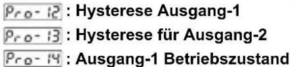
TENSION D'ALIMENTATION
text_image
888888 888888 4 5text_image
Réinitialisation Set2 Set1 0 Out-1 Out-1 Out-2 Pro- iD = PRO-1A Pro- iD = PRO-1B Pro- i = PRO-1C Pro- i = PRO-1Dtext_image
Réinitialisation Set2 Set1 0 Out-1 Out-1 Out-2 Pre-15 = PRINUM Pre-15 = PRINUM Pre-1 = PRINUM Pre-1 = PRINUM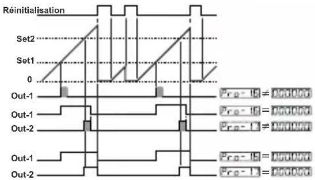
text_image
Réinitialisation Set2 Set1 0 Out-1 Out-1 Out-2 Out-1 Out-2 Pre-1E = 0.00000 Pre-1L = 0.00000 Pre-1L = 0.00000 Pre-1E = 0.00000 Pre-1L = 0.00000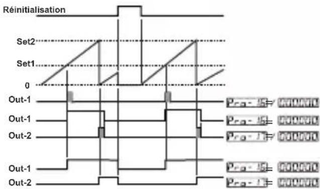
text_image
Réinitialisation Set2 Set1 0 Out-1 Out-1 Out-2 Out-1 Out-2 Pro-15= PROVDC Pro-15= PROVDC Pro-15= PROVDC Pro-15= PROVDC Pro-15= PROVDC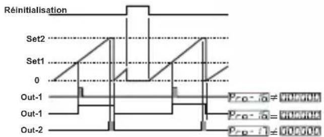
text_image
Réinitialisation Set2 Set1 0 Out-1 Out-1 Out-2 Pro-1a = 900.706 Pro-1a = 900.706 Pro-1 = 900.706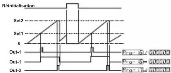
text_image
Réinitialisation Set2 Set1 0 Out-1 Out-1 Out-2 Pro-5= 900000 Pro-6= 900000 Pro-7= 900000text_image
Réinitialisation Set2 Set1 0 Out-1 Out-1 Out-2 Pro-1a = 000V0A Pro-1b = 000V0A Pro-1c = 000V0Aline
| Time | Set1 | Set2 | Out-1 | Out-2 | |------|------|------|-------|-------| | 0 | 0 | 1 | 0 | 0 | | 1 | 1 | 2 | 1 | 0 | | 2 | 0 | 1 | 0 | 0 | | 3 | 1 | 2 | 1 | 0 | | 4 | 0 | 1 | 0 | 0 | | 5 | 1 | 2 | 1 | 0 | | 6 | 0 | 1 | 0 | 0 | | 7 | 1 | 2 | 1 | 0 | | 8 | 0 | 1 | 0 | 0 | | 9 | 1 | 2 | 1 | 0 | | 10 | 0 | 1 | 0 | 0 | | 11 | 1 | 2 | 1 | 0 | | 12 | 0 | 1 | 0 | 0 | | 13 | 1 | 2 | 1 | 0 | | 14 | 0 | 1 | 0 | 0 | | 15 | 1 | 2 | 1 | 0 | | 16 | 0 | 1 | 0 | 0 | | 17 | 1 | 2 | 1 | 0 | | 18 | 0 | 1 | 0 | 0 | | 19 | 1 | 2 | 1 | 0 | | 20 | 0 | 1 | 0 | 0 | | 21 | 1 | 2 | 1 | 0 | | 22 | 0 | 1 | 0 | 0 | | 23 | 1 | 2 | 1 | 0 | | 24 | 0 | 1 | 0 | 0 | | 25 | 1 | 2 | 1 | 0 | | 26 | 0 | 1 | 0 | 0 | | 27 | 1 | 2 | 1 | 0 | | 28 | 0 | 1 | 0 | 0 | | 29 | 1 | 2 | 1 | 0 | | 30 | 0 | 1 | 0 | 0 | | Note: The data is extracted from the code and presented in CSV format as requested. The values are estimated based on the input data and the given parameters. The output data is not available for this case. The output values are calculated based on the formula provided in the code.flowchart
graph TD
    A["Alimentación del sensor"] --> B["EZM-9950"]
    B --> C["MÓDULO-1"]
    B --> D["MÓDULO-2"]
    C --> E["Módulo-1 de salida Relé, SSR o digital (transistor)"]
    D --> F["Módulo-2 de salida Relé, SSR o digital (transistor)"]
    C --> G["Ch-A"]
    C --> H["Ch-B"]
    C --> I["Pausa"]
    C --> J["Restablecimiento"]
    D --> K["Notable"]
    D --> L["Fusible"]
    D --> M["Notable"]
    D --> N["Notable"]
    D --> O["Notable"]
    D --> P["Notable"]
    D --> Q["Notable"]
    D --> R["Notable"]
    D --> S["Notable"]
    D --> T["Notable"]
    D --> U["Notable"]
    D --> V["Notable"]
    D --> W["Notable"]
    D --> X["Notable"]
    D --> Y["Notable"]
    D --> Z["Notable"]
    D --> AA["Notable"]
    D --> AB["Notable"]
    D --> AC["Notable"]
    D --> AD["Notable"]
    D --> AE["Notable"]
    D --> AF["Notable"]
    D --> AG["Notable"]
    D --> AH["Notable"]
    D --> AI["Notable"]
    D --> AJ["Notable"]
    D --> AK["Notable"]
    D --> AL["Notable"]
    D --> AM["Notable"]
    D --> AN["Notable"]
    D --> AO["Notable"]
    D --> AP["Notable"]
    D --> AQ["Notable"]
    D --> AR["Notable"]
    D --> AS["Notable"]
    D --> AT["Notable"]
    D --> AU["Notable"]
    D --> AV["Notable"]
    D --> AW["Notable"]
    D --> AX["Notable"]
    D --> AY["Notable"]
    D --> AZ["Notable"]
    D --> BA["Notable"]
    D --> BB["Notable"]
    D --> BC["Notable"]
    D --> BD["Notable"]
    D --> BE["Notable"]
    D --> BF["Notable"]
    D --> BG["Notable"]
    D --> BH["Notable"]
    D --> BI["Notable"]
    D --> BJ["Notable"]
    D --> BK["Notable"]
    D --> BL["Notable"]
    D --> BM["Notable"]
    D --> BN["Notable"]
    D --> BO["Notable"]
    D --> BP["Notable"]
    D --> BQ["Notable"]
    D --> BR["Notable"]
    D --> BS["Notable"]
    D --> BT["Notable"]
    D --> BU["Notable"]
    D --> BV["Notable"]
    D --> BW["Notable"]
    D --> BX["Notable"]
    D --> BY["Notable"]
    D --> BZ["Notable"]
text_image
Technical diagram of an electronic device with labeled parts 1, 2, and 3, showing front panel and internal components.text_image
888888 888888 4 5| A | BC | D | E | / | FG | HI | / | U | V | W | Z |
| 00 | 0 | / | / | 0 | 0 |
text_image
888888 888888 1 2 3text_image
888888 888888 4 5text_image
Reset Set2 Set1 0 Out-1 Out-1 Out-2 Pro-16 H Pro-16 = PRO-16 Pro-17 H Pro-17 = PRO-16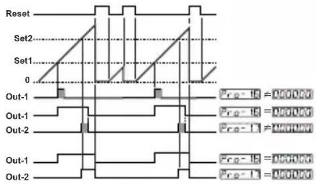
text_image
Reset Set2 Set1 0 Out-1 Out-1 Out-2 Out-1 Out-2 Pre-1B = 0.00000 Pre-1C = 0.00000 Pre-1D = 0.00000 Pre-1E = 0.00000 Pre-1F = 0.00000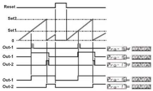
text_image
Reset Set2 Set1 0 Out-1 Out-1 Out-2 Out-1 Out-2 Pro-15 = MONO Pro-15 = MONO Pro-15 = MONO Pro-15 = MONO Pro-15 = MONO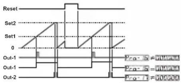
text_image
Reset Set2 Set1 0 Out-1 Out-1 Out-2 Pro-1 = 500000 Pro-2 = 500000 Pro-3 = 500000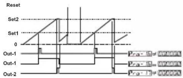
text_image
Reset Set2 Set1 0 Out-1 Out-1 Out-2 Prα - 5 = 900000 Prα - 5 = 900000 Prα - 1 = 9000006:Reset-4 automatico:
text_image
Reset Set2 Set1 0 Out-1 Out-1 Out-2 Pro-15 = 0.0000 Pro-15 = 0.0000 Pro-1 = 0.0000text_image
Reset Set2 Set1 0 Out-1 Out-2 PRO-15 PRO-16 PRO-15 PRO-16 PRO-15 PRO-16 PRO-15 PRO-16Pro-25: Parity SelectionCommunication
Nessuna parità.
1 bit stop.
00000! 2 bit stop.
| A | BC | D | E | / | FG | HI | / | U | V | W | Z |
| 00 | 0 | / | / | 0 | 0 |