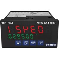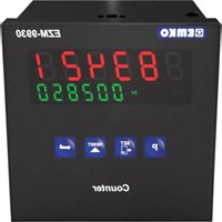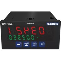
EZM-4930 - Programmable meter Emko - Free user manual and instructions
Find the device manual for free EZM-4930 Emko in PDF.


User questions about EZM-4930 Emko
0 question about this device. Answer the ones you know or ask your own.
Ask a new question about this device
Download the instructions for your Programmable meter in PDF format for free! Find your manual EZM-4930 - Emko and take your electronic device back in hand. On this page are published all the documents necessary for the use of your device. EZM-4930 by Emko.
USER MANUAL EZM-4930 Emko
natural_image
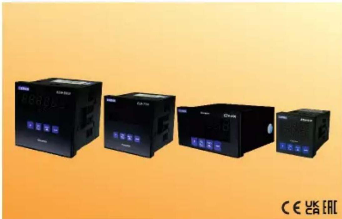
Four black industrial control unit blocks with digital displays and buttons, displayed against an orange gradient background (no readable text or symbols on main devices)EZM-4430,EZM-4930,EZM-7730,EZM-9930 Programmable Counters
EZM-4430, EZM-4930, EZM-7730, EZM-9930
Programmable Counters
- 6 digits Process (PV) and 6 digits Set (SV) Value Display
- Operation with 1 Set Value
- Reset, Pause and ChA-ChB Counting Inputs
- NPN/PNP Type Operation
- Operation with Automatic and Manual Reset
- INC,DEC,INC/INC,INC/DEC,UP/DOWN, x1 / x2 / x4 Counting with
Phase Shifting Property - Multiplication Coefficient and Decimal Point Position
SPECIFICATIONS :
INPUTS :
Counting Inputs (Ch-A, Ch-B): Switch, Proximity, Capacitive sensor or encoder can be connected.
Reset Input: Switch, Proximity, Capacitive sensor or encoder can be connected.
Pause Input: Switch, Proximity, Capacitive sensor or encoder can be connected.
Sensor Type Selection: NPN or PNP can be selected.
Reset Function: Automatic or Manual.
Count Input Types and Maximum Frequency :
Process Output : Relay Output (5A@250V\~ at Resistive Load)
SUPPLY VOLTAGE
230 V ∼ 50/60 Hz (-15%; +10%) 3VA
115V~(-15%; +10%) 3VA
24V ∼ 50/60 Hz (-15% ; +10%) 3VA
24 V≈(-%15;+%15) 4 VA/4W
(Must be determined in order.)
DISPLAY :
Process Value Display :
EZM-4430 : 8 mm Red 6 digit LED Display
EZM-4930 : 13.2 mm Red 6 digit LED Display
EZM-7730 : 10.8 mm Red 6 digit LED Display
EZM-9930 : 13.2 mm Red 6 digit LED Display
Set Value Display :
EZM-4430 : 8 mm Green 6 digit LED Display
EZM-4930 : 8 mm Green 6 digit LED Display
EZM-7730 : 8 mm Green 6 digit LED Display
EZM-9930 : 8 mm Green 6 digit LED Display
LED Display : SV(Set value), OP(Output Position) LEDs.
ENVIRONMENTAL RATINGS and PHYSICAL SPECIFICATIONS
Operating Temperature: 0...50°C
Humidity noncondensing),
Protection Class: altf65nt,1p20ear.
Weight:
EZM-4430 : 210 gr.
EZM-4930 : 240 gr.
EZM-7730 : 270 gr.
EZM-9930 : 340 gr.
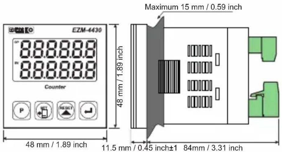
Dimensions:
EZM-4430 : (48 x 48mmDepthmm)
EZM-4930 : (96 x 48mmDepthmm)
EZM-7730 : (72 x72mm, De 5 mm)
EZM-9930 : (96 x 96mmDepthmm)
Panel Cut-Out:
EZM-4430 : (48 x 48mm)
EZM-4930 : (96 x 48mm)
EZM-7730 : (72 x72mm)
EZM-9930 : (96 x 96mm)
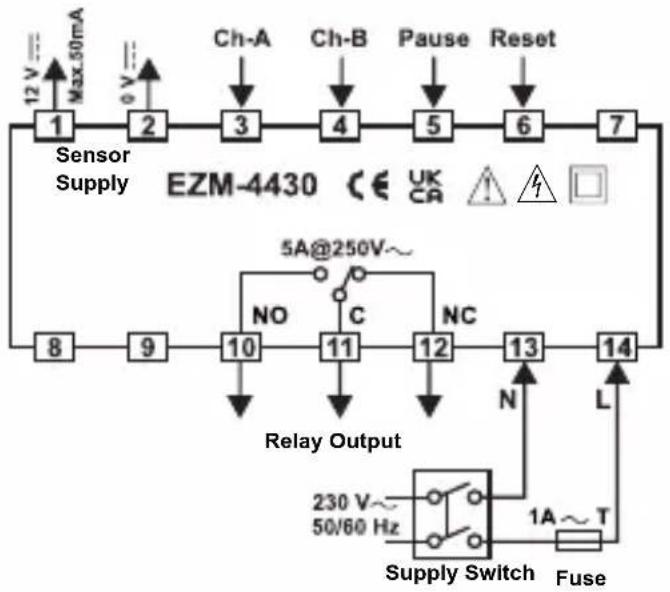
flowchart
graph TD
    A["Sensor Supply"] --> B["1"]
    B --> C["2"]
    C --> D["3"]
    D --> E["4"]
    E --> F["5"]
    F --> G["6"]
    G --> H["7"]
    H --> I["8"]
    I --> J["9"]
    J --> K["10"]
    K --> L["11"]
    L --> M["12"]
    M --> N["13"]
    N --> O["14"]
    O --> P["Supply Switch"]
    P --> Q["230 V~ 50/60 Hz"]
    P --> R["1A~ T Fuse"]
    S["Ch-A"] --> D
    T["Ch-B"] --> E
    U["Pause"] --> F
    V["Reset"] --> G
    W["NO"] --> K
    X["C"] --> L
    Y["NC"] --> M
    Z["N"] --> N
    AA["L"] --> O
    AB["5A@250V~"] --> K
    AC["Max.50mA"] --> A
    AD["UK CR"] --> H
    AE["+"] --> AF[" "]
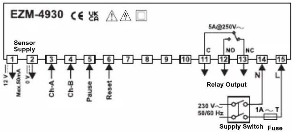
flowchart
graph LR
    A["Sensor Supply"] --> B["1"]
    B --> C["2"]
    C --> D["3"]
    D --> E["4"]
    E --> F["5"]
    F --> G["6"]
    G --> H["7"]
    H --> I["8"]
    I --> J["9"]
    J --> K["10"]
    K --> L["11"]
    L --> M["12"]
    M --> N["13"]
    N --> O["14"]
    O --> P["15"]
    P --> Q["Supply Switch"]
    Q --> R["Relay Output"]
    R --> S["5A@250V~"]
    R --> T["NO"]
    R --> U["NC"]
    R --> V["N"]
    R --> W["L"]
    X["Max: 50mA"] --> Y["Ch-A"]
    Z["V"] --> AA["Ch-B"]
    AB["Pause"] --> AC["Reset"]
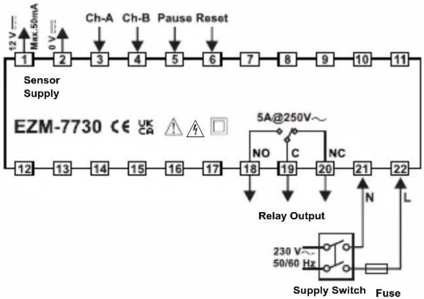
flowchart
graph LR
    A["Sensor Supply"] --> B["12 V Max.50mA"]
    B --> C["2 0 V"]
    C --> D["3 Ch-A"]
    D --> E["4 Ch-B"]
    E --> F["5 Pause Reset"]
    F --> G["6"]
    G --> H["7"]
    H --> I["8"]
    I --> J["9"]
    J --> K["10"]
    K --> L["11"]
    L --> M["EZM-7730 CE UK CA"]
    M --> N["12"]
    N --> O["13"]
    O --> P["14"]
    P --> Q["15"]
    Q --> R["16"]
    R --> S["17"]
    S --> T["18"]
    T --> U["19"]
    U --> V["20"]
    V --> W["21"]
    W --> X["22"]
    X --> Y["Relay Output"]
    Y --> Z["N L"]
    Z --> AA["Supply Switch"]
    AA --> AB["Fuse"]
    AB --> AC["230 V~ 50/60 Hz"]
    AC --> AD["NO C NC"]
    AD --> AE["5A@250V~"]
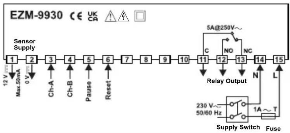
flowchart
graph LR
    A["Sensor Supply"] --> B["1"]
    B --> C["2"]
    C --> D["3"]
    D --> E["4"]
    E --> F["5"]
    F --> G["6"]
    G --> H["7"]
    H --> I["8"]
    I --> J["9"]
    J --> K["10"]
    K --> L["11"]
    L --> M["12"]
    M --> N["13"]
    N --> O["14"]
    O --> P["15"]
    P --> Q["Supply Switch"]
    Q --> R["230 V~ 50/60 Hz"]
    Q --> S["1A~ T"]
    Q --> T["L"]
    U["Max.50mA"] --> V["12 V"]
    W["Ch-A"] --> X["Ch-B"]
    Y["Ch-A"] --> Z["Ch-B"]
    AA["Pause"] --> AB["Reset"]
    AC["5A@250V~"] --> AD["C"]
    AE["NO"] --> AF["NC"]
    AG["N"] --> AH["L"]
DIMENSIONS
text_image
EZM-4430 8.8.8.8.8 8.8.8.8.8 Counter P SET RESET 48 mm / 1.89 inch 48 mm / 1.89 inch Maximum 15 mm / 0.59 inch 11.5 mm / 0.45 inch±1 84mm / 3.31 inch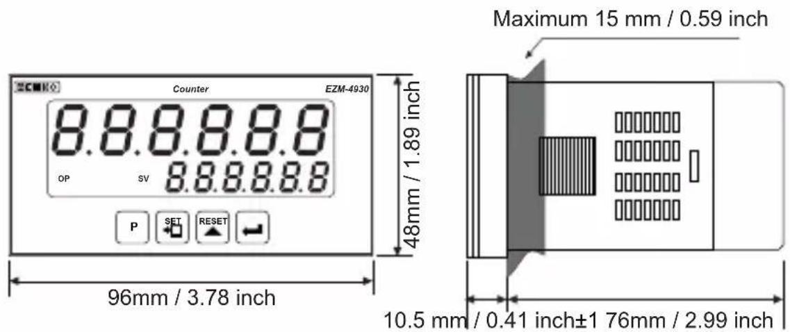
text_image
Counter EZM-4930 8.8.8.8.8 OP SV 8.8.8.8.8 P SET RESET 48mm / 1.89 inch 96mm / 3.78 inch Maximum 15 mm / 0.59 inch 10.5 mm / 0.41 inch±1 76mm / 2.99 inch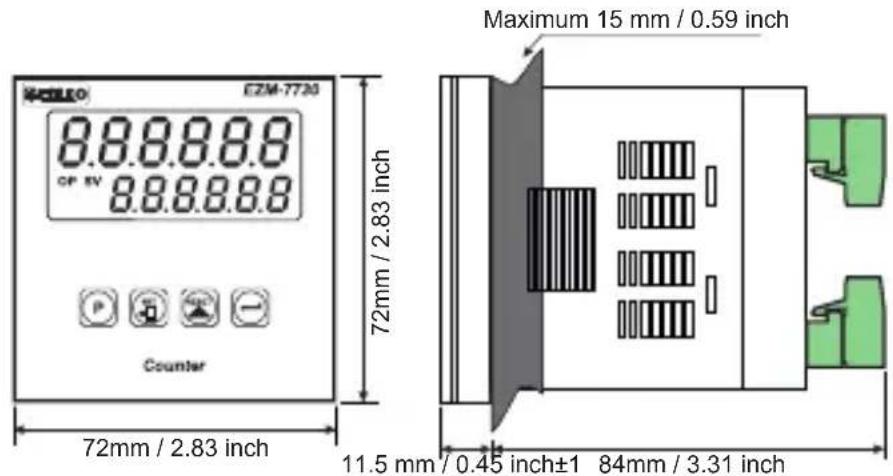
text_image
EZM-7720 8.8.8.8.8 CF 5V 8.8.8.8.8 Counter 72mm / 2.83 inch Maximum 15 mm / 0.59 inch 11.5 mm / 0.45 inch±1 84mm / 3.31 inch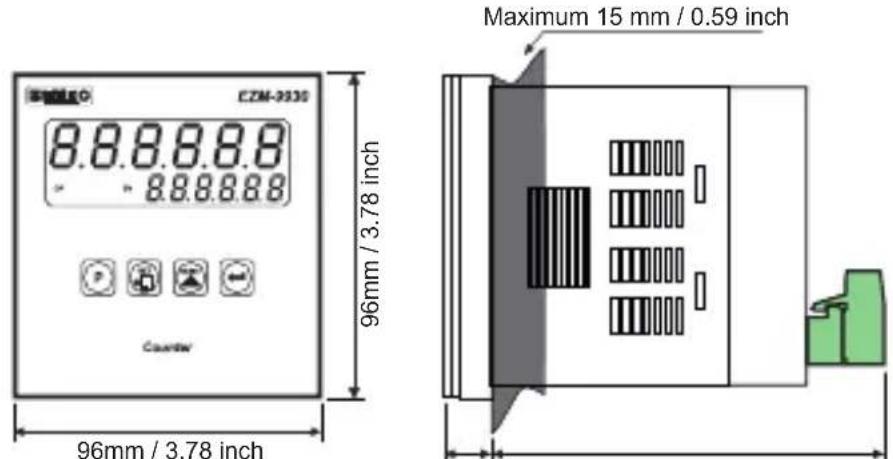
text_image
CZM-2030 8.8.8.8.8 8.8.8.8.8 Counter 96mm / 3.78 inch Maximum 15 mm / 0.59 inch 96mm / 3.78 inch11.5 mm / 0.45 inch±1 84mm / 3.31 inch
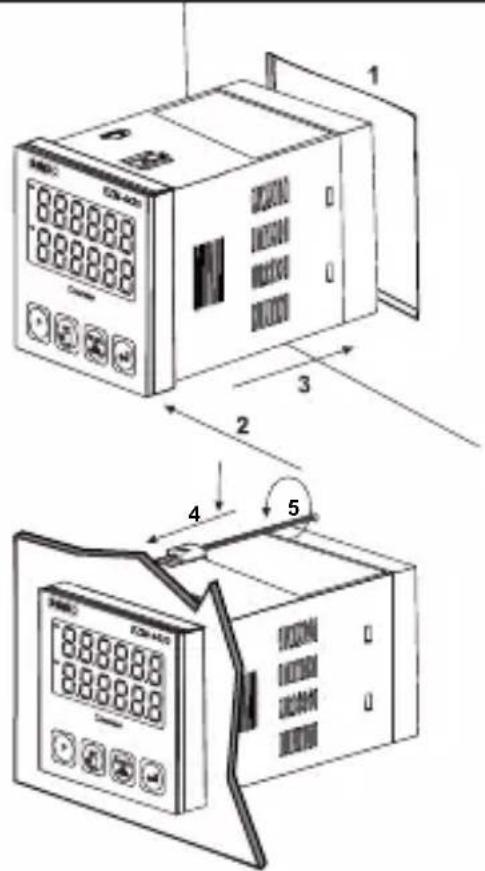
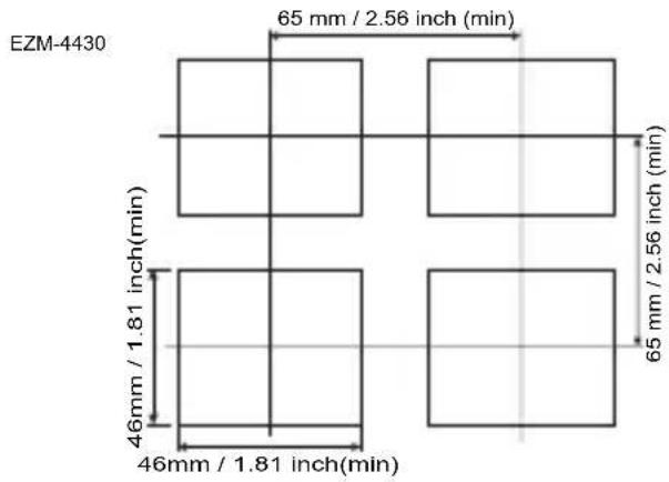
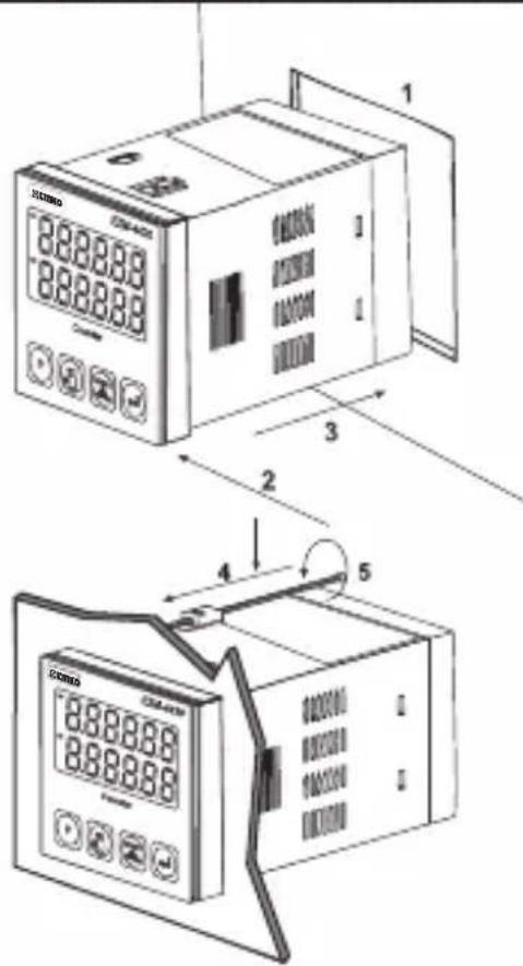
PANEL MOUNTING
text_image
Technical diagram showing two views of a digital temperature meter with labeled components and measurement annotations.1- Before mounting the device in your panel, make sure that the panel cut-out is suitable.
2-Check front panel gasket Position.
3- Insert the device through the cut-out. If the mounting clamp are on the unit, put out them before inserting the unit to the panel.
4- Insert the unit in the panel cut-out from the front side.
5- Insert the mounting clamps to the holes that located top and bottom sides of device and screw up the fixing screws until the unit completely immobile within the panel.
other
EZM-4430 | Dimension | Value | | :--- | :--- | | Top Left | 65 mm / 2.56 inch (min) | | Top Right | 65 mm / 2.56 inch (min) | | Bottom Left | 46 mm / 1.81 inch (min) | | Bottom Right | 46 mm / 1.81 inch (min) |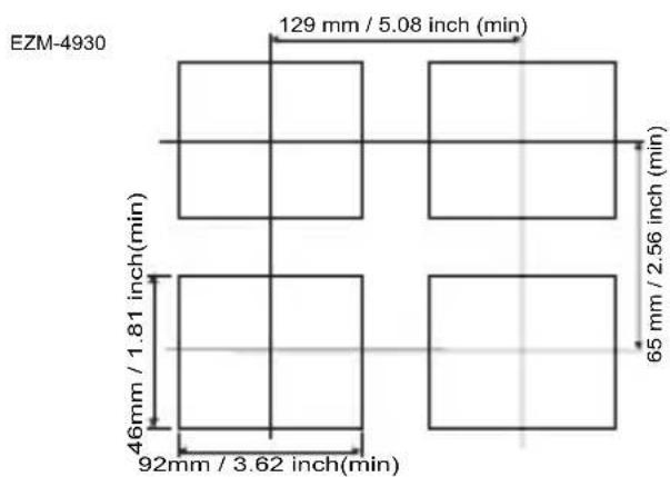
other
EZM-4930 | Dimension | Value | | :--- | :--- | | Top Section | 129 mm / 5.08 inch (min) | | Middle Section | 65 mm / 2.56 inch (min) | | Bottom Section | 46 mm / 1.81 inch (min) | | Bottom Section | 92 mm / 3.62 inch (min) |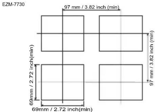
other
EZM-7730 | Dimension | Value | | :--- | :--- | | Top Left | 97 mm / 3.82 inch (min) | | Top Right | 97 mm / 3.82 inch (min) | | Bottom Left | 69 mm / 2.72 inch (min) | | Bottom Right | 69 mm / 2.72 inch (min) |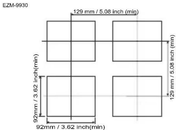
other
EZM-9930 | Dimension | Value | | :--- | :--- | | Top Left Square | 129 mm / 5.08 inch (min) | | Top Right Square | 129 mm / 5.08 inch (min) | | Bottom Left Square | 92 mm / 3.62 inch (min) | | Bottom Right Square | 92 mm / 3.62 inch (min) |Accessing and Changing the Set Values
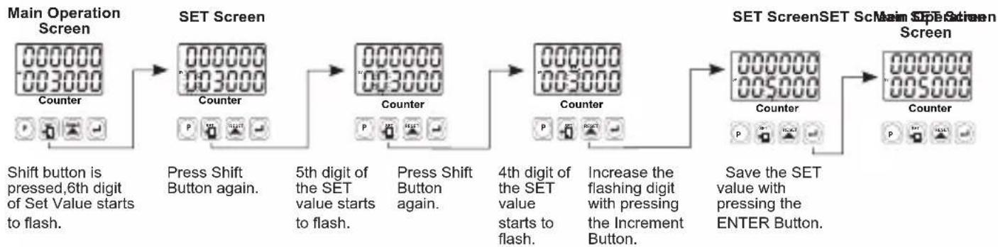
flowchart
graph LR
    A["Main Operation Screen"] --> B["SET Screen"]
    B --> C["5th digit of the SET value starts to flash."]
    C --> D["4th digit of the SET value starts to flash."]
    D --> E["Save the SET value with pressing the ENTER Button."]
    E --> F["SET ScreenSET Screen"]

    style A fill:#f9f,stroke:#333
    style B fill:#ccf,stroke:#333
    style C fill:#cfc,stroke:#333
    style D fill:#fcc,stroke:#333
    style E fill:#cff,stroke:#333
    style F fill:#ffc,stroke:#333

    note1["Shift button is pressed, 6th digit of Set Value starts to flash."] --> A
    note2["Press Shift Button again."] --> B
    note3["Press Shift Button again."] --> C
    note4["Increase the flashing digit with pressing the Increment Button."] --> D
    note5["Save the SET value with pressing the ENTER Button."] --> E
Accessing to the Program Parameters
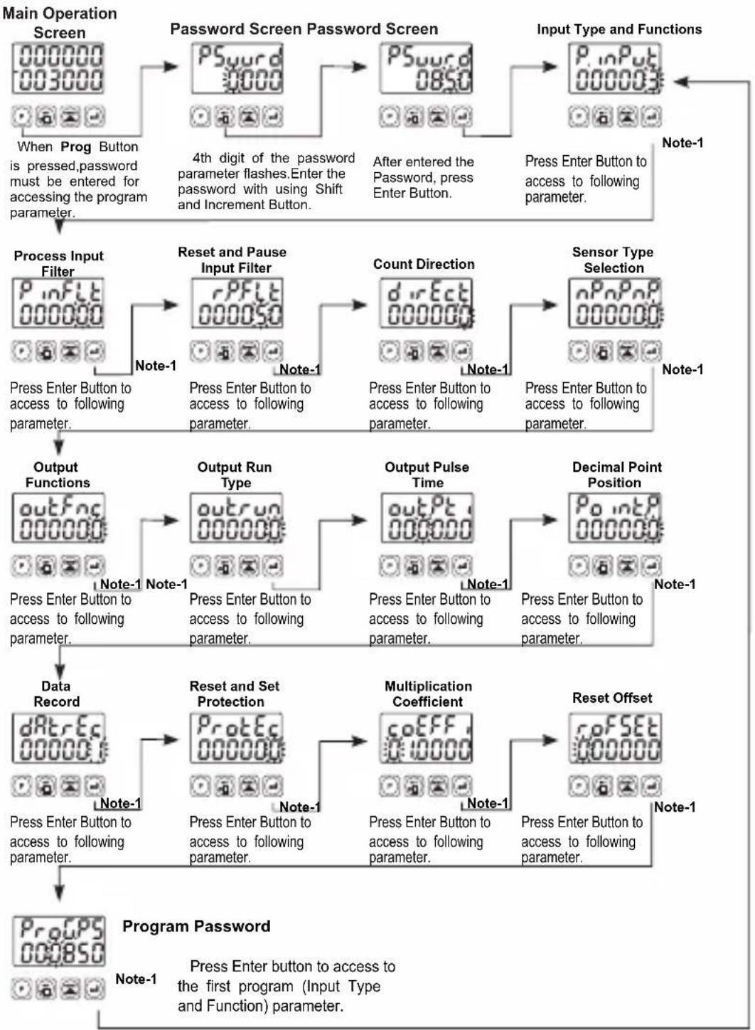
flowchart
graph TD
    A["Main Operation Screen"] --> B["Password Screen Password Screen"]
    B --> C["Input Type and Functions"]
    C --> D["Process Input Filter"]
    D --> E["Reset and Pause Input Filter"]
    E --> F["Count Direction"]
    F --> G["Sensor Type Selection"]
    G --> H["Output Functions"]
    H --> I["Output Run Type"]
    I --> J["Output Pulse Time"]
    J --> K["Decimal Point Position"]
    K --> L["Data Record"]
    L --> M["Reset and Set Protection"]
    M --> N["Multiplication Coefficient"]
    N --> O["Reset Offset"]
    O --> P["Program Password"]

    style A fill:#f9f,stroke:#333
    style P fill:#f9f,stroke:#333

    note1["4th digit of the password parameter flashes. Enter the password with using Shift and Increment Button."]
    note2["Press Enter Button to access to following parameter."]
    note3["Press Enter Button to access to following parameter."]
    note4["Press Enter Button to access to following parameter."]
    note5["Press Enter Button to access to following parameter."]
    note6["Press Enter Button to access to following parameter."]

    subgraph Note1
        direction TB
        A1["000000 003000"]
        A2["000000"]
        A3["000000"]
        A4["000000"]
        A5["000000"]
        A6["000000"]
        A7["000000"]
        A8["000000"]
        A9["000000"]
        A10["000000"]
        A11["000000"]
        A12["000000"]
        A13["000000"]
        A14["000000"]
        A15["000000"]
        A16["000000"]
        A17["000000"]
        A18["000000"]
        A19["000000"]
        A20["000000"]
        A21["000000"]
        A22["000000"]
        A23["000000"]
        A24["000000"]
        A25["000000"]
        A26["000000"]
        A27["000000"]
        A28["000000"]
        A29["000000"]
        A31["1.5", 1.5, 1.5, 1.5, 1.5, 1.5, 1.5, 1.5, 1.5, 1.5, 1.5, 1.5, 1.5, 1.5, 1.5, 1.5, 1.5, 1.5, 1.5, 1.5, 1.5, 1.5"]:::note
        note2:::note
        note3:::note
        note4:::note
        note5:::note
        note6:::note
        note7:::note
        note8:::note
        note9:::note
        note1:::note
        note11:::note
        note12:::note
        note13:::note
        note14:::note
        note15:::note
        note16:::note
        note17:::note
        note18:::note
        note19:::note
        note2:::note
        note3:::note
        note4:::note
        note5:::note
        note6:::note
        note7:::note
        note8:::note
        note9:::note
        note1:::note
        note11:::note
        note12:::note
        note13:::note
        note14:::note
    end
Note 1- Parameter value can be changed with Incrament button. When the Enter button is pressed, parameter value will be saved and following parameter is accessed.
Note 2- Press "P" button is exit without saving the parameter value. Thus Main Operation Screen is appeared.
Parameter Definitions
P. inPut : Input Type and Functions (Default=3)
0 : U(p)Cunt on rising edge of Ch-A input.
1: Downc(DEF)on rising edge of Ch-A input.
2 Updown on rising edge of Ch-A input count on rising edge of Ch-B input.(INC/DEC)
3 : Upcount on rising edge of Ch-A input, Upcount on rising edge of Ch-B input (INC/INC)
4 : Up/downnt on rising edge of Ch-A input when Ch-B is at 0 count on rising edge of Ch-A when Ch-B is at 1. (UP/DOWN)
5 : x1 P.(faserShiftingtal Encoder)
6 : x2 P.(faserShiftingtal Encoder)
7 : x4 P.(faser Environmental Encoder)
P_inFLT : (Default=0)Filter time for Ch-A and Ch-B Inputs
It is used to protect against the electrical contact debounce or the signal that is less than the determined pulse time.
It can be adjusted from 000000 to 000050 milisecond.
rPFLT: (Default=50)Filter time for Reset and Pause Inputs
It is used to protect against the electrical contact debounce or the signal that is less than the determined pulse time.
It can be adjusted from 000002 to 000050 milisecond.
dircEst:Count Direction (Default=0)
Upcount. ( 0 -->Preset )
00000: Downcount. ( Preset--> 0 )
nP_nP_nP :Sensor Type Selection (Default=0)
NPN Sensor type is selected.
900001 PNP Sensor type is selected.
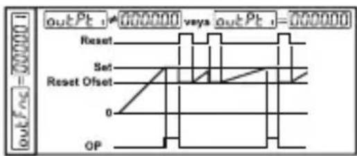
outFnc : Output Functions (Default=0)
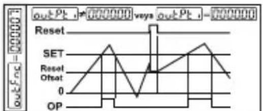
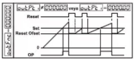
0:Manuel Reset-1: Process counts, until manuel reset happens. When count value reaches the Set value, Output Position is changed.
text_image
outPt - 000000 vaya outPt - 000000 Reset Set Reset Offset 0 OP1:Manuel Reset-2: Process counts, until manuel reset happens. When count value reaches the Set value, Output Position is changed. Counting doesn't change continue over Set value. Output Position doesn't change, until manuel reset happens.
2:Manuel Reset-3: Process counts, until manuel reset happens. When count value reaches the Set value, Output Position is changed. After the end of the Output Pulse Time output positions changes the old position.
3: Automatic Reset-1: When count value reaches the Set value, Output position is changed. Process value automatically and counting will continue from "0"(up count) or "Set"(downcount). After the end of the Output Pulse Time outPt, output positions changes the old position.
4: Automatic Reset-2: When count value reaches the Set value, Output position is changed. Counting doesn't continue over the Set value. Process value is reset automatically, counting continue from "0" (upcount) or "Set" (downcount) and Output position changes the old position at the end of the output pulse time.
5: Automatic Reset-3: When count value reaches the Set value, Output position is changed. Count value becomes zero. (For 0->P) Counting restarts on "0" value, but Set Value is shown on the Process value screen. Output position becomes the old and the Real count value can be seen at the end of output pulse time. outPt
6: Automatic Reset-4: When count value reaches the Set value, Output position is changed. Count value is automatically reset and counting will continue (for 0->P) and Output position changes the old position at the end of the output pulse time.
7: Automatic Reset-5: Process counts, until manuel reset happens. Output pulse time does not take into consideration. This function can be preferred on systems that, upcounts or downcounts at the same time.
text_image
outPc = 000000 outPc t = 000000 vays outPc t = 000000 Reset Set Reset Offset 0 OP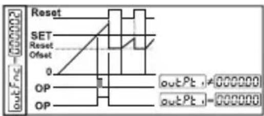
text_image
outFoc Reset SET Reset Offset 0 OP OP outPt ≠ 000000 outPt ≠ 000000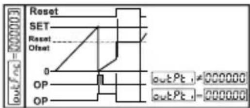
text_image
Reset SET Reset Offset 0 OP OP outPt ≠ 000000 outPt = 000000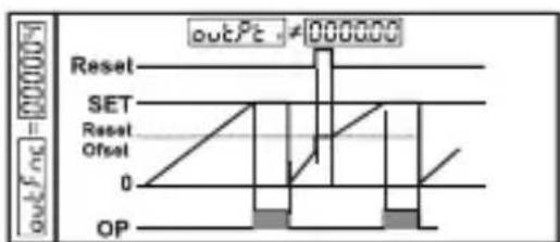
text_image
outPc = 000000 Reset SET Reset Offset 0 OP outPc ≠ 000000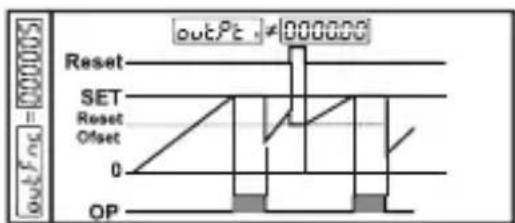
text_image
outPt ≠ 000000 Reset SET Reset Offset 0 OP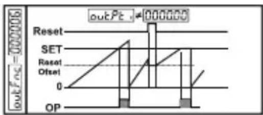
text_image
outPc = 000006 Reset SET Reset Offset 0 OP outPc - 000006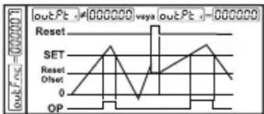
line
| Time | SET | Reset | Offset | OP | |------|------|-------|--------|------| | 0 | 0 | 0 | 0 | 0 | | 1 | 1 | 0 | 0 | 0 | | 2 | 2 | 0 | 0 | 0 | | 3 | 1 | 0 | 0 | 0 | | 4 | 0 | 0 | 0 | 0 | | 5 | 1 | 0 | 0 | 0 | | 6 | 2 | 0 | 0 | 0 | | 7 | 1 | 0 | 0 | 0 | | 8 | 0 | 0 | 0 | 0 | | 9 | 1 | 0 | 0 | 0 | | 10 | 2 | 0 | 0 | 0 | | 11 | 1 | 0 | 0 | 0 | | 12 | 0 | 0 | 0 | 0 | | 13 | 1 | 0 | 0 | 0 | | 14 | 2 | 0 | 0 | 0 | | 15 | 1 | 0 | 0 | 0 | | 16 | 0 | 0 | 0 | 0 | | 17 | 1 | 0 | 0 | 0 | | 18 | 2 | 0 | 0 | 0 | | 19 | 1 | 0 | 0 | 0 | | 20 | 0 | 0 | 0 | 0 | | 21 | 1 | 0 | 0 | 0 | | 22 | 2 | 0 | 0 | 0 | | 23 | 1 | 0 | 0 | 0 | | 24 | 0 | 0 | 0 | 0 | | 25 | 1 | 0 | 0 | 0 | | 26 | 2 | 0 | 0 | 0 | | 27 | 1 | 0 | 0 | 0 | | 28 | 0 | 0 | 0 | 0 | | 29 | 1 | 0 | 0 | 0 | | 30 | 2 | 0 | 0 | 0 | | 31 | 1 | 0 | 0 | 0 | | 32 | 0 | 0 | 0 | 0 | | 33 | 1 | 0 | 0 | 0 | | 34 | 2 | 0 | 0 | 0 | | 35 | 1 | 0 | 0 | 0 | | 36 | 0 | 0 | 0 | 0 | | Note: The data is extracted from the code and presented in CSV format as requested. The values for 'SET' and 'OP' are estimated based on the input 'set'. There is only one data series in this case.outrun : Output Run Type (Default=0)
Normally De-energised.
000001 Normally Energised.
outPt : Output Pulse Time (Default=0.00)
It determines how long Output will be active. It can be adjusted from 00.00 to 99.99 seconds. If it is 00.00 second, then it operates indefinitely.
Point: Point Position (Default=0)
No point.
Between first and second digits.
000002 Between second and third digits. 000000
Between third and fourth digits.
Between fourth and fifth digits.
dRt rEc : Data Record (Default=1)
Count value is saved to memory when power is disconnected and restored on power up.
Count value is not saved to memory when power is disconnected.
ProtEc: Reset and Set Protection (Default=0)
No Reset and Set protection.
000001 Only Reset button protection is active.
000002 Only Set button protection is active.
000003 Full Protection.Reset and Set button protection is active.
coEFF: Multiplication Coefficient (Default=01.0000)
The Count value that is read from Process input, is multiplied with this value. Parameter value can be adjusted from 00.0000 to 99.9999. If this parameter is adjusted to "01.0000" then this parameter has no effect on Process input count, so Process value equal to the Process input count.
r.oFSET : Reset Offset (Default=0)
It can be adjusted from 000000 to 500000. When Process is manually reset, count process starts from this value.
ProGPS : Program Password (Default=0)
It is used for accessing to the program parameters.
It can be adjusted from 000000 to 009999.
If it is 000000 ; there is no password protection while entering to the program parameters.
If operator accesses to the program parameters by entering "0" to PSword, then the operator can only see the parameter without changing, except ProGPS
Failure Messages in EZM-XX30 Programmable Counter
Password ScreenMain Operation Screen Input Type and RefenOffsets Parameter
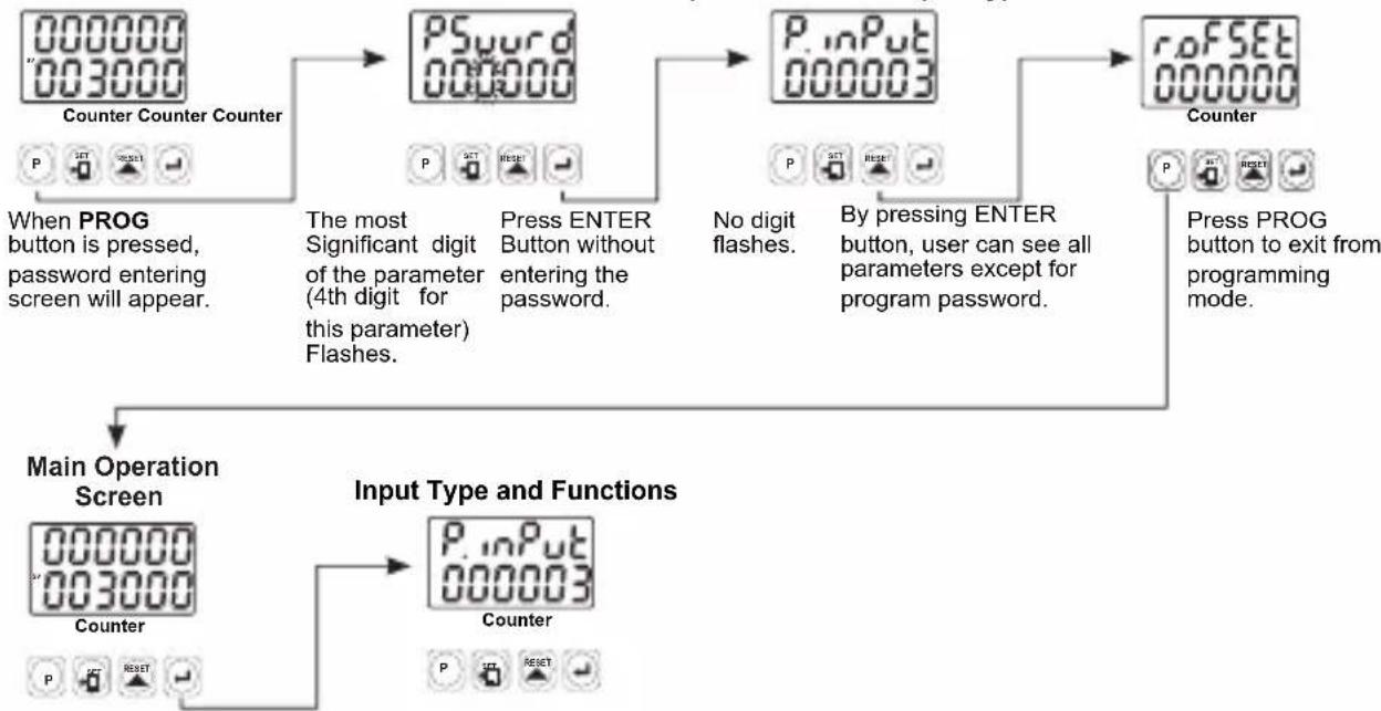
flowchart
graph TD
    A["Counter Counter"] --> B["When PROG button is pressed, password entering screen will appear."]
    B --> C["The most Significant digit of the parameter (4th digit for this parameter) Flashes."]
    C --> D["Press ENTER Button without entering the password."]
    D --> E["No digit flashes."]
    E --> F["By pressing ENTER button, user can see all parameters except for program password."]
    F --> G["Press PROG button to exit from programming mode."]
    G --> H["Counter"]
    H --> I["Main Operation Screen"]
    I --> J["Input Type and Functions"]
    J --> K["Counter"]
Continue to press ENTER button for scanning the parameters.
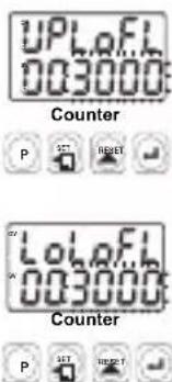
text_image
UPLaFL 003000 Counter P SET RESET LPLaFL 003000 Counter P SET RESET1- If Actual Value is flashing and counting is stopped; It appears if any of the count value is bigger than the maximum count value. To remove this warning and reset the count value press RESET button.
2- If Actual Value is flashing and counting is stopped; It appears if any of the count value is lower than the minimum count value. To remove this warning and reset the count value press RESET button.
Installation

Before beginning installation of this product, please read the instruction manual and warnings below carefully.
In package
-One piece unit
-Two pieces mounting clamp
-One piece instruction manual
A visual inspection of this product for possible damage occurred during shipment is recommended before installation. It is your responsibility to ensure that qualified mechanical and electrical technicians install this product.
If there is danger of serious accident resulting from a failure or defect in this unit, power off the system and the electrical connection of the device from the system.
The unit is normally supplied without a power switch or a fuse. Use power switch and fuse as required.
Be sure to use the rated power supply voltage to protect the unit against damage and to prevent failure.
Keep the power off until all of the wiring is completed so that electric shock and trouble with the unit can be prevented.
Never attempt to disassemble, modify or repair this unit. Tampering with the unit may results in malfunction, electric shock or fire.
Do not use the unit in combustible or explosive gaseous atmospheres. During the equipment is putted in hole on the metal panel while mechanical installation some metal burrs can cause injury on hands, you must be careful.
Montage of the product on a system must be done with it's mounting clamp. Do not do the montage of the device with in appropriate mounting clamp. Be sure that device will not fall while doing the montage.
It is your responsibility if this equipment is used in a manner not specified in this instruction manual.
Warranty
EMKO Elektronik warrants that the equipment delivered is free from defects in material and workmanship. This warranty is provided for a period of two years. The warranty period starts from the delivery date.
This warranty is in force if duty and responsibilities which are determined in warranty document and instruction manual performs by the customer completely.
Maintenance
Repairs should only be performed by trained and specialized personnel. Cut power to the device before accessing internal parts.
Do not clean the case with hydrocarbon-based solvents (Petrol, Trichlorethylene etc.). Use of these solvents can reduce the mechanical reliability of the device. Use a cloth dampened in ethyl alcohol or water to clean the external plastic case.
Other Informations
Manufacturer Information:
Emko Elektronik Sanayi ve Ticaret A.Ş.
Bursa Organize Sanayi Bölgesi, (Fethiye OSB Mah.) Ali Osman Sönmez Bulvarı, 2. Sokak, No:3 16215 BURSA - TÜRKİYE
Phone : +90 224 261 1900 Fax : +90 224 261 1912
Repair and maintenance service information:
Emko Elektronik Sanayi ve Ticaret A.Ş.
1 Relay Output (5A @ 250 V \~ at resistive load)
All order information of EZM-XX30 series are given on the table at above. User may form appropriate device configuration from information and codes that at the table and convert it to the ordering codes.
Firstly, supply voltage then other specifications must be determined.
Please fill the order code blanks according to your needs.
Please contact us, if your needs are out of the standards.

Symbol Means Vac ∼
Symbol Means Vdc ——
Symbol Means Vac and Vdc ≌

Thank you very much for your preference to use Emko Elektronik products, please visit our web page to download detailed user manual.
www.emkoelektronik.com.tr
natural_image
Four black industrial control unit blocks with digital displays and buttons, displayed against an orange gradient background (no readable text or symbols on main devices)EZM-4430, EZM-4930, EZM-7730, EZM-9930 Programmierbare Zähler
EZM-7730: (72x72mm, Tiefe:95.5 mm)
EZM-9930: (96x96mm, Tiefe: 96mm)
Fronttafel:
EZM-4430: (48 x 48 mm)
EZM-4930: (96 x 48 mm)
EZM-7730: (72 x 72 mm)
EZM-9930: (96 x 96 mm)
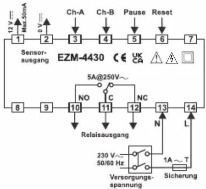
flowchart
graph TD
    A["12V Max 50mA"] --> B["2"]
    C["0V"] --> D["3"]
    E["Ch-A"] --> F["4"]
    G["Ch-B"] --> H["5"]
    I["Pause"] --> J["6"]
    K["Reset"] --> L["7"]
    M["Sensor-ausgang"] --> N["EZM-4430"]
    N --> O["5A@250V~"]
    O --> P["NO"]
    O --> Q["C"]
    O --> R["NC"]
    P --> S["Relaisausgang"]
    Q --> S
    R --> S
    S --> T["10"]
    S --> U["11"]
    S --> V["12"]
    S --> W["13"]
    T --> X["8"]
    U --> Y["9"]
    V --> Z["14"]
    W --> AA["14"]
    AA --> AB["N"]
    AA --> AC["L"]
    AB --> AD["230V~ 50/60 Hz"]
    AC --> AE["Sicherung"]
    AE --> AF["Sicherung spannung"]
    AF --> AG["Versorgungs-spannung"]

flowchart
graph LR
    A["Sensor-<br>ausgang"] --> B["1"]
    B --> C["2"]
    C --> D["3"]
    D --> E["4"]
    E --> F["5"]
    F --> G["6"]
    G --> H["7"]
    H --> I["8"]
    I --> J["9"]
    J --> K["10"]
    K --> L["11"]
    L --> M["12"]
    M --> N["13"]
    N --> O["14"]
    O --> P["15"]

    subgraph Sensor-
ausgang
        Q["Max 50mA"] --> R["12 V"]
        S["0 V"] --> T["0 V"]
        U["Ch-A"] --> V["Ch-A"]
        W["Ch-B"] --> X["Ch-B"]
        Y["Pause"] --> Z["Pause"]
        AA["Reset"] --> AB["Reset"]
    end

    subgraph Relaisausgang
        AC["C"] --> AD["5A@250V~"]
        AE["NO"] --> AF["NC"]
        AG["N"] --> AH["L"]
        AI["Versorgungs-<br>spannung"] --> AJ["230 V~ 50/60 Hz"]
        AK["Sicherung"] --> AL["1A ~ T"]
    end
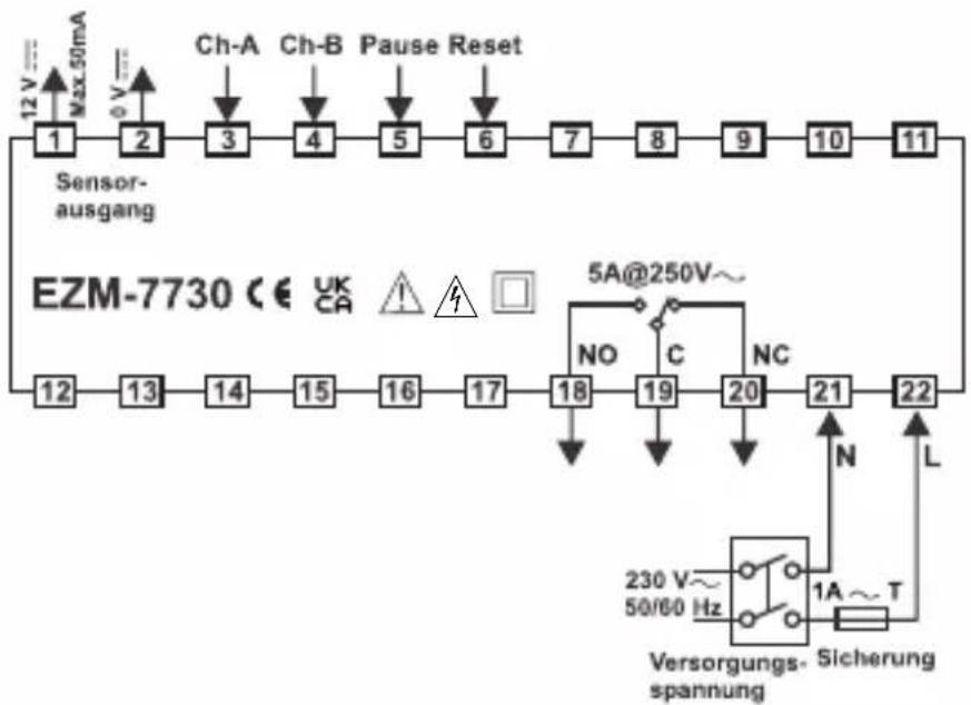
flowchart
graph TD
    A["12 V Max 50mA"] --> B["Sensor-ausgang"]
    B --> C["Ch-A"]
    B --> D["Ch-B"]
    B --> E["Pause Reset"]
    C --> F["1"]
    D --> G["2"]
    E --> H["3"]
    F --> I["4"]
    G --> J["5"]
    H --> K["6"]
    I --> L["7"]
    J --> M["8"]
    K --> N["9"]
    L --> O["10"]
    M --> P["11"]
    N --> Q["12"]
    O --> R["13"]
    P --> S["14"]
    Q --> T["15"]
    R --> U["16"]
    S --> V["17"]
    T --> W["18"]
    U --> X["19"]
    V --> Y["20"]
    W --> Z["21"]
    X --> AA["22"]
    Y --> AB["N"]
    Z --> AC["L"]
    AD["5A@250V~"] --> AE["NO"]
    AE --> AF["C"]
    AF --> AG["NC"]
    AG --> AH["230 V~ 50/60 Hz"]
    AH --> AI["Sicherung spannung"]
    AI --> AJ["1A ~ T"]
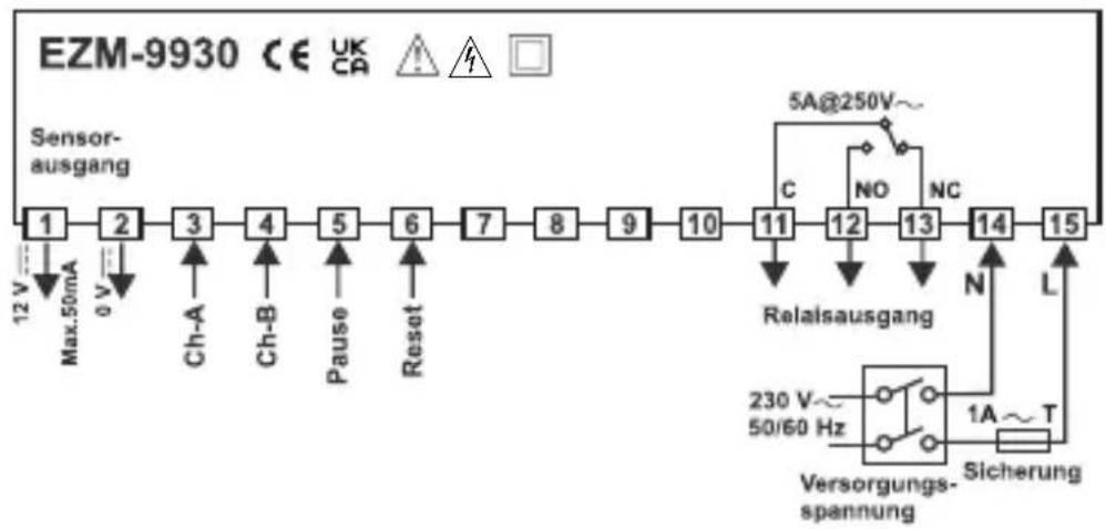
flowchart
graph LR
    A["12 V Max.50mA"] --> B["2"]
    B --> C["3"]
    C --> D["4"]
    D --> E["5"]
    E --> F["6"]
    F --> G["7"]
    G --> H["8"]
    H --> I["9"]
    I --> J["10"]
    J --> K["11"]
    K --> L["12"]
    L --> M["13"]
    M --> N["14"]
    N --> O["15"]
    P["Sensor-ausgang"] --> Q["Ch-A"]
    P --> R["Ch-B"]
    P --> S["Pause"]
    P --> T["Reset"]
    U["5A@250V~"] --> V["C"]
    V --> W["NO"]
    V --> X["NC"]
    Y["Relaisausgang"] --> Z["N"]
    AA["Sicherung"] --> AB["T"]
    AC["230 V~ 50/60 Hz"] --> AD["○"]
    AE["Sicherung spannung"] --> AF["○"]
    AG["1A~T"] --> AH["○"]
ABMESSUNGEN
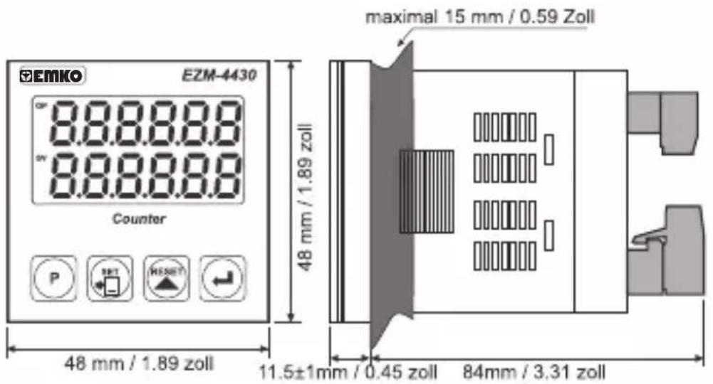
text_image
EMKO EZM-4430 8.8.8.8.8 8.8.8.8.8 Counter P SHT HENSY 48 mm / 1.89 zoll 48 mm / 1.89 zoll maximal 15 mm / 0.59 Zoll 11.5±1mm / 0.45 zoll 84mm / 3.31 zoll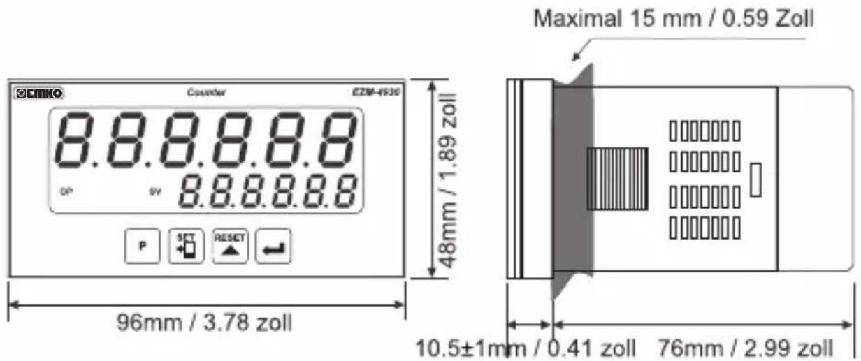
text_image
EMIKO Counter E2M-4930 8.8.8.8.8 op sv 8.8.8.8.8 P SET RESET 48mm / 1.89 zoll Maximal 15 mm / 0.59 Zoll 96mm / 3.78 zoll 10.5±1mm / 0.41 zoll 76mm / 2.99 zoll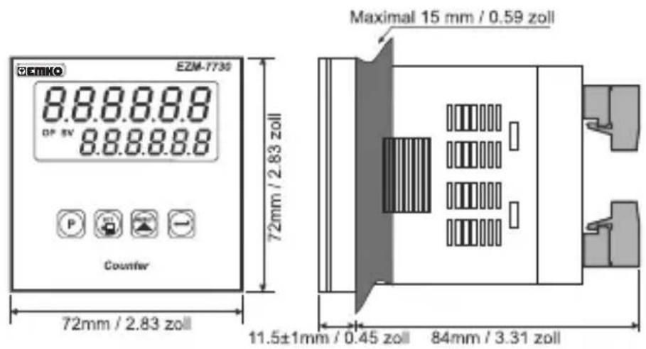
text_image
CEIMKO EZM-7730 8.8.8.8.8 DP 5V 8.8.8.8.8 P Counter 72mm / 2.83 zoll Maximal 15 mm / 0.59 zoll 11.5±1mm / 0.45 zoll 84mm / 3.31 zoll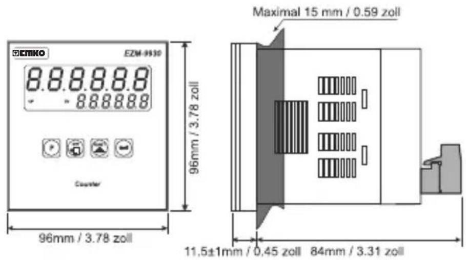
text_image
E2M-9530 E2M-9530 8.8.8.8.8 - 8.8.8.8.8 Counter Maximal 15 mm / 0.59 zoll 96mm / 3.78 zoll 11,5±1mm / 0,45 zoll 84mm / 3.31 zollSCHALTTAFELMONTAGE
text_image
1 2 3 4 5other
EZM-4930 | Dimension | Value | | :--- | :--- | | Top Section | 129 mm / 5.08 zoll (min) | | Middle Section | 65 mm / 2.56 zoll (min) | | Bottom Section | 92 mm / 3.62 zoll (min) | | Left Section | 46 mm / 1.61 zoll (min) | E label at bottom right indicates '46mm / 1.61 zoll (min)' and '92mm / 3.62 zoll (min)'.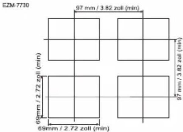
other
EZM-7730 | Grid | Dimension (mm) | Zoll (min) | |---|---|---| | Top Left | 97 | 3.82 | | Top Right | 97 | 3.82 | | Bottom Left | 69 | 2.72 | | Bottom Right | 69 | 2.72 | The chart displays a grid layout with four rectangular units, each annotated with a precise numerical value for the top row and column width.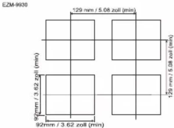
other
EZM-9930 | Grid | Dimension (mm) | Zoll (min) | |---|---|---| | Top Left | 129 | 5.08 | | Top Right | 129 | 5.08 | | Bottom Left | 92 | 3.62 | | Bottom Right | 92 | 3.62 | The chart displays a grid layout with four rectangular units, each annotated with its respective dimension and zoll length. The top row contains the maximum dimension of 129 mm / 5.08 zoll (min), while the bottom row contains the minimum dimension of 92 mm / 3.62 zoll (min). The grid spacing is indicated by the horizontal line at 129 mm / 5.08 zoll (min).$$ \boxed {\text { outFnc }} = 0 0 0 0 0 1 $$
$$ \boxed {\text { outfnc }} = 0 0 0 0 0 2 $$
$$ \boxed {\text { outFnc }} = 0 0 0 0 0 3 $$
$$ \boxed {\text { outFnc }} = 0 0 0 0 0 4 $$
$$ \boxed {\text { outfnc }} = 0 0 0 0 0 5 $$
natural_image
Four black industrial control unit units with digital displays and buttons, displayed against a gradient orange background (no visible text or symbols on devices)EZM-4430,EZM-4930,EZM-7730,EZM-9930 Compteurs Programmables
TENSION D'ALIMENTATION
230 V ∼ 50/60 Hz (-15% ;+10%) 3 VA
115 V~(-15%; +10%) 3 VA
24V ∼ 50/60 Hz (-15% ; +10%) 3 VA
24 V≈(-%15;+%15) 4 VA/4W
other
| Dimension | Value (Pouces) | | :--- | :--- | | Top Section | 65 | | Middle Section | 2.56 | | Bottom Section | 2.56 | | Bottom Section | 1.81 | | Middle Section | 1.81 | | Top Section | 2.56 | The bottom section contains two identical dimensions of 46 mm / 1.81 pounces (min). The top and middle sections are equal in length, while the bottom section is equal in height.EZM-4930
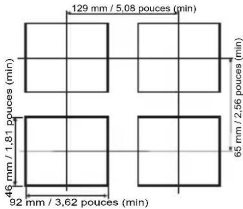
other
| Dimension | Value (m) | | :--- | :--- | | Top Left Square | 129 | | Top Right Square | 5,08 | | Bottom Left Square | 46 | | Bottom Right Square | 2,56 | | Bottom Right Square | 3,62 | The chart displays a grid layout with four rectangular units each containing a unique dimension value (e.g., '129 mm / 5,08 pouces (min)'). The top left is labeled '46 mm / 1,81 pouces (min)', the bottom left is labeled '92 mm / 3,62 pouces (min)', and the bottom right is labeled '65 mm / 2,56 pouces (min)'.EZM-7730
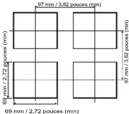
other
| Dimension | Value (m) | | :--- | :--- | | Top Left Square | 97 mm / 3,82 pouces (min) | | Top Right Square | 97 mm / 3,82 pouces (min) | | Bottom Left Square | 69 mm / 2,72 pouces (min) | | Bottom Right Square | 69 mm / 2,72 pouces (min) |EZM-9930

other
| Dimension | Pouce Rate (min) | | :--- | :--- | | Top Left | 129 | | Top Right | 5,08 | | Bottom Left | 92 | | Bottom Right | 3,62 | The diagram displays four rectangular units with horizontal and vertical lines indicating spacing of the top left unit. The bottom center is labeled '92 mm / 3,62 pouces (min)' and the top center is labeled '129 mm / 5,08 pouces (min)'.line
| Signal | Value | |---|---| | Reset | 0 | | SET | 100 | | Reset Offset | 50 | | OP | 0 |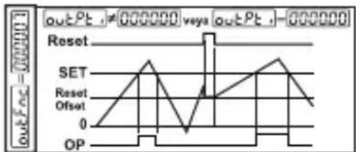
text_image
outPt ,#000000 vsa outPt ,-000000 Reset SET Reset Offset 0 OPnatural_image
Four black industrial control unit blocks with digital displays and buttons, displayed against a solid orange background (no readable text or symbols on devices)EZM-4430, EZM-4930, EZM-7730, EZM-9930 Contadores Programables
line
| Signal | Value | |--------|-------| | set | 0 | | SET | 1.5 | | Reset | 0 | | Offset | 0 | | OP | 1.5 |text_image
UPLoFL 003000 Counter P SET RESET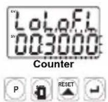
text_image
LoLofL 003000 Counter P SET RESETnatural_image
Four black industrial control unit blocks with digital displays and buttons, displayed against a solid orange background (no readable text or symbols on units)EZM-4430, EZM-4930, EZM-7730, EZM-9930 Contatori Programmabili
text_image
888888 888888 1 2 3 4 5other
EZM-4430 | Location | Length (mm) | Pollicle Duration (min) | | :--- | :--- | :--- | | Top Left | 65 | 2.56 | | Top Right | 65 | 2.56 | | Bottom Left | 46 | 1.81 | | Bottom Right | 46 | 1.81 | The diagram includes four rectangular units with horizontal and vertical grid lines indicating measurements.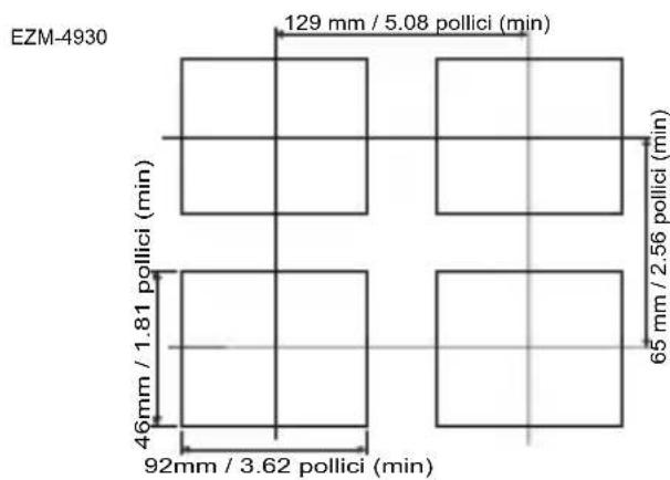
other
EZM-4930 | Dimension | Value | | :--- | :--- | | Top Left | 129 mm / 5.08 pollici (min) | | Top Right | 65 mm / 2.56 pollici (min) | | Bottom Left | 46 mm / 1.81 pollici (min) | | Bottom Right | 92 mm / 3.62 pollici (min) |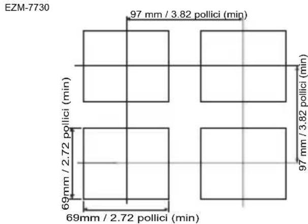
other
EZM-7730 | Grid | Dimension (mm) | Pollici (min) | |---|---|---| | Top Left | 97 | 3.82 | | Top Right | 97 | 3.82 | | Bottom Left | 69 | 2.72 | | Bottom Right | 69 | 2.72 | The top row contains a dimension label of 97 mm / 3.82 pollici (min), while the bottom row contains a dimension label of 69 mm / 2.72 pollici (min). The grid is divided into four equal rectangles.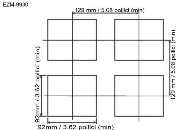
other
EZM-9930 | Dimension | Value | | :--- | :--- | | Top Section | 129 mm / 5.08 pollici (min) | | Middle Section | 92 mm / 3.62 pollici (min) | | Bottom Section | 129 mm / 5.08 pollici (min) | | Bottom Section (Left) | 92 mm / 3.62 pollici (min) | The chart displays a grid layout with four rectangular boxes, each containing a central rectangle and two adjacent rectangles. The top section contains the maximum dimension at 129 mm / 5.08 pollici (min), while the bottom section has the minimum dimension at 92 mm / 3.62 pollici (min). The center region is shaded blue for scale.text_image
outP outP = 0.00000 Reset SET Reset Offset 0 OP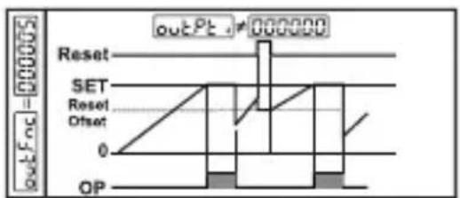
text_image
outFoc = 000005 outPt - 000000 Reset SET Reset Offset 0 OP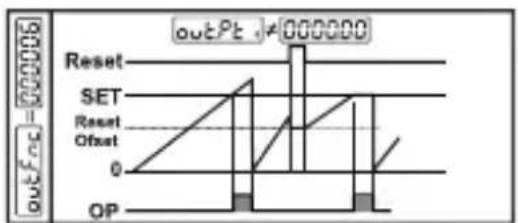
text_image
outPt ≠ 000000 Reset SET Reset Offset 0 OP