
DRC5040 - Dashcam Pro-User - Free user manual and instructions
Find the device manual for free DRC5040 Pro-User in PDF.


| Brand | Pro-User |
| Model | DRC5040 |
| Product type | Wireless backup camera kit with monitor |
| Screen size | 5 inches (12.7 cm) |
| Display resolution | 854 x 480 pixels |
| Camera sensor | 1/3" CMOS |
| Camera resolution | 1920 x 1080 pixels (Full HD) |
| Viewing angle | 110° |
| Transmission frequency | 2.4 GHz (ISM band) |
| Range without obstacles | Up to 150 meters |
| Power supply | 12V / 24V DC |
| Camera consumption (IR off) | <200 mA |
| Camera consumption (IR on) | <300 mA |
| Monitor consumption (standby) | <120 mA |
| Monitor consumption (active) | <250 mA |
| Main functions | Wireless backup camera, guideline display, channel switching (1/2), brightness/contrast/color adjustments, auto pairing |
| Installation | Camera mounting on license plate or other location, monitor on windshield with suction cup, wiring to reverse lights |
| Warranty | 2 years |
| Operating temperature | Not explicitly specified, but suction cup application recommended between 21°C and 38°C |
Frequently Asked Questions - DRC5040 Pro-User
User questions about DRC5040 Pro-User
0 question about this device. Answer the ones you know or ask your own.
Ask a new question about this device
Download the instructions for your Dashcam in PDF format for free! Find your manual DRC5040 - Pro-User and take your electronic device back in hand. On this page are published all the documents necessary for the use of your device. DRC5040 by Pro-User.
USER MANUAL DRC5040 Pro-User

DIGITAL WIRELESS BACK-UP CAMERASYSTEM
WITH 12,7 CM / 5" MONITOR

DIGITALES KABELLOSES RÜCKFAHRKAMERA- SYSTEM
MIT 12,7 CM / 5" MONITOR

DIGITAAL DRAADLOOS CAMERASYSTEEM
MET 12,7 CM / 5" MONITOR

Read this manual before using this product.
CONTENTS
Introduction P.2
Important Safety Instructions P.2
Package contents P.3
Installation P.3
Operation P.7
Technical specifications P.9
Warranty P.9
INTRODUCTION
The Pro-User Electronics DRC5040 is a member of the family of advanced car back-up camera systems manufactured by Pro User Electronics.
The Pro-User Electronics digital back-up camera and monitor with built in transmitter box, when used as described, will improve your ability to see behind your car, camper, trailer, or mini-van. We have taken numerous measures in quality control to ensure that your product arrives in top condition, and will perform to your satisfaction.
Please carefully read and follow the following safety and operating instructions.
IMPORTANT SAFETY INSTRUCTIONS
Before installation Before installation
If you are not confident working with 12V/24V DC vehicle wiring, removing and reinstalling interior panels, carpeting, dashboards or other components of your vehicle, contact the vehicle's manufacturer, or consider having the camera system professionally installed.
InterferenceInterference
This device is free from interferences coming from Bluetooth, cell phones, Wi-Fi routers, power lines and other various electrical equipment.
Repair Repair
The camera system should not be opened. Any attempt at modification or repair by the user will entail the loss of your guarantee.
PACKAGE CONTENTS
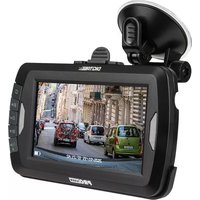
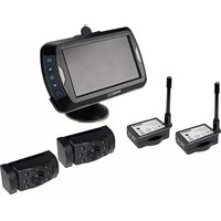
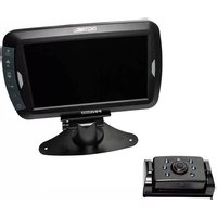
1) Monitor
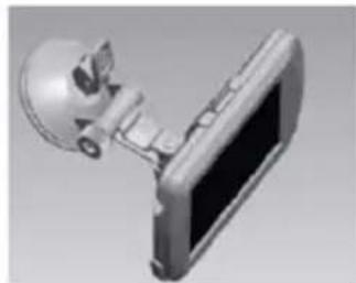
2) Suction mount for monitor
3) Monitor power cable
4) Camera with mounting plate
5) Mounting Accessories
6) User manual
INSTALLATION
These instructions do not apply to all vehicles. They are only my aim to engage a general guide due to the number of different makeAs & models for vehicles specific questions contact your vehicle's manufacturer.s manufacturer.
Camera installationCamera installation
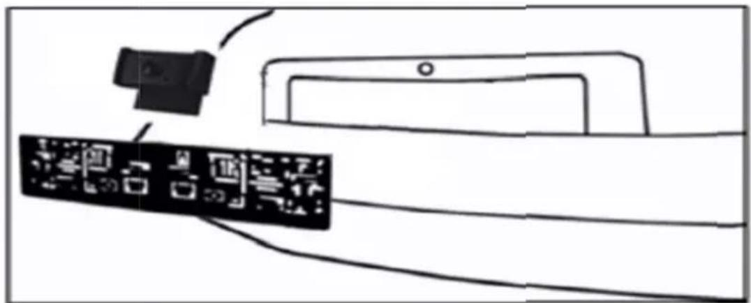
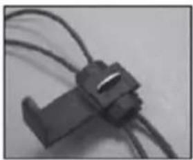
There are several ways to mount the camera on the back of your car. But the most convenient is to mount it near the license plate. Supplied is one mounting plate that can be fixed behind the license plate, and the mounting plate have been installed in the camera. The camera itself is screwed on the mounting plate. The camera is tiltable, camera angle can be adjusted manually on vertical direction. Make sure that its field of view and detection are not obstructed.
1) Remove the rear license plate, and then loosen the license plate bolts/screws.
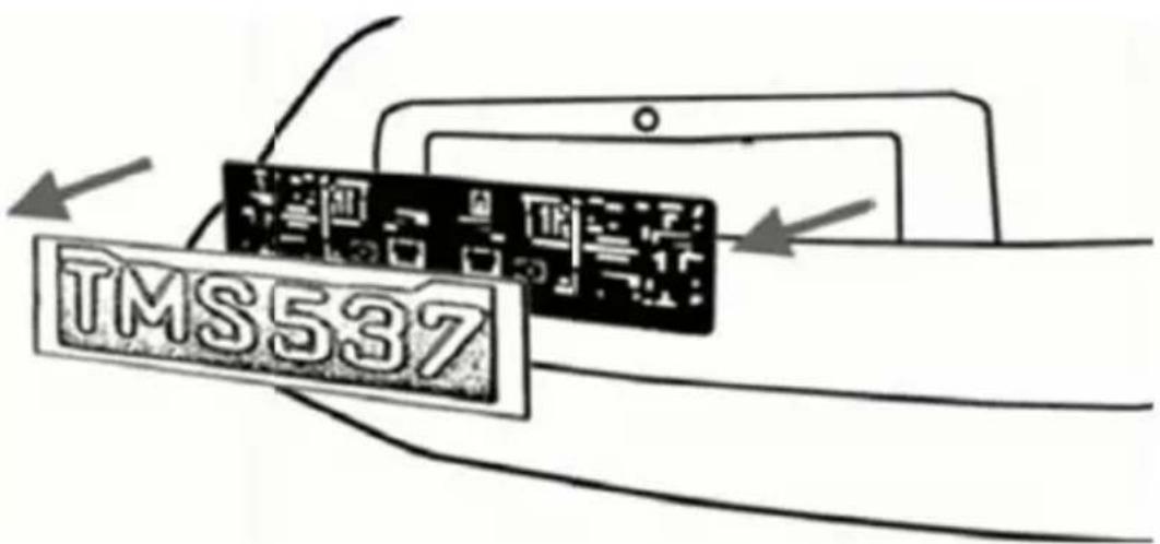
INSTALLATION
2) Position the supplied mounting plate (with camera together) behind the license plate bracket. Secure both license plate bracket and mounting plates with the license plate bracket bolts/screws.
3) Mount the license plate on the license plate bracket.
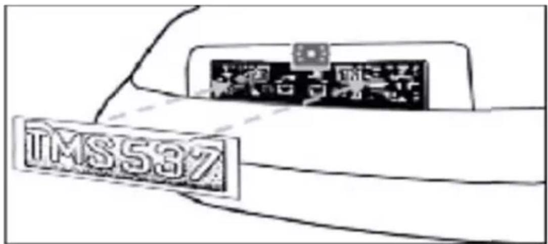
With some type of cars it is not possible to mount the camera near the license plate. You may have to find another spot at the back of your car to mount it.
INSTALLATION
After choosing the method of mounting, follow these installation steps:
1) Choose a routing path for the camera's power cable through the vehicle's body to the reverse light circuit. If in doubt, seek professional installation assistance.
2) Some vehicles may have a hole available to pass the wire through, such as where the license plate light is mounted, or you can drill a hole close to where the power cable is attached to the camera. Once you have chosen where the cable will enter the vehicle's body, remove the camera. If you are able to use an existing opening, skip the next two steps.
3) Before you drill a hole you must check and see what's behind where you are drilling. If there are any vehicle components, such as electrical parts or fuel system components behind where you are drilling, you must take whatever precaution is necessary not to damage them. Remove the license plate and camera before drilling.
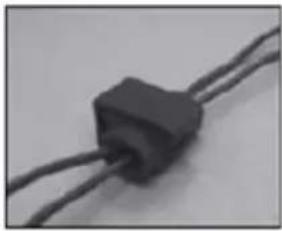
4) After you have drilled the hole, insert the supplied grommet, then pass the camera cables through the grommet into the vehicle. You must use the grommet to prevent the metal edge of the hole from cutting the camera cable.
5) Next you'll need to find the vehicle's reverse lights. Turn the vehicle's ignition key to the accessory position, engage the parking brake and put the car in reverse. Look at the vehicle's tail lights to see where the reverse lights are located, they are the white lights. To locate the reverse light's 12 V / 24 V + wire it will be necessary to gain access to the rear of the vehicle's tail light. For help locating the vehicle's reverse light circuit contact your vehicle's manufacturer for vehicle specific wiring diagrams.
6) Once you have located the reverse light circuit you will have to route the camera cable to that location. You must securely fasten the power cable to prevent it from being caught on any vehicle component such as the trunk hinge. Never route the cable on the outside of the vehicle!
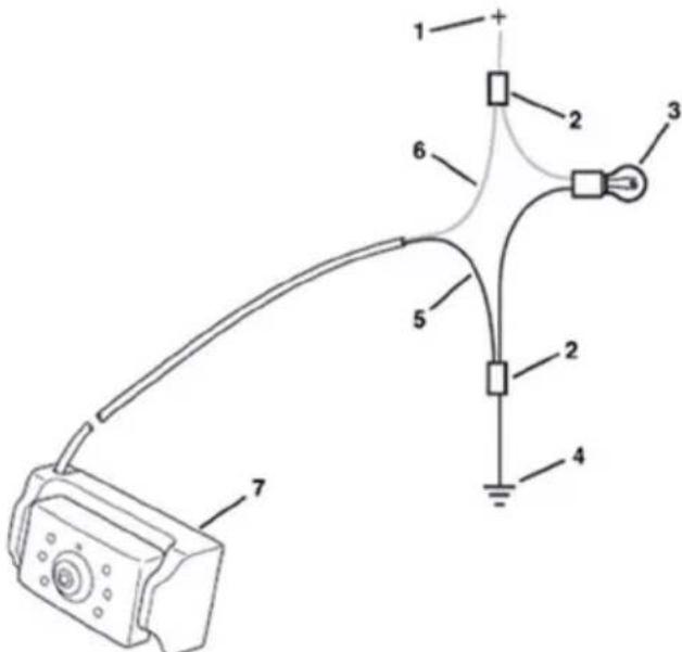
7) The reverse light sockets on most vehicles have two wires connected to them. Usually the negative wire is black and the positive wire is a colored wire. If you are uncertain about the wiring, you can use a 12V/24V multimeter available at most auto parts stores to determine which is the positive wire. Follow the manufacturer's instructions for the safe use of the multimeter.
1 = Positive (+) 2 = Connector 3 = Lamp 4 = Negative (-) 5 = Camera Negative (-) 6 = Camera Positive (+) 7 = Camera
INSTALLATION
8) After determining which wire is the positive and which is the negative, turn off the ignition key, then remove the battery's negative cable.
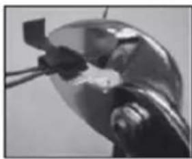
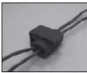
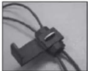
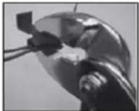
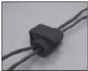
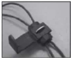
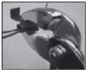
9) Splice the red wire using the supplied in-line wire connectors to the reverse light's positive (+) wire. Use a set of slip joint pliers to squeeze the TAP and insure good Connection.

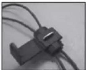
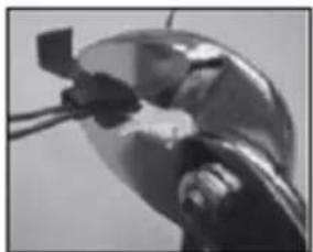
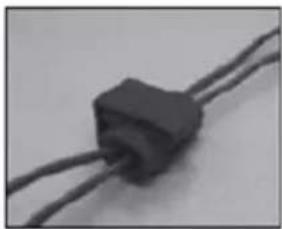
10) Next splice the black wire of the camera power cable to the reverse light's negative (-) wire or ground.
11) Replace the reverse light bulb, and then re-install the light socket. Secure all the wires with cable ties or electrical tape.
12) Re-attach the negative battery cable to the battery.
Monitor InstallationMonitor Installation
When choosing a location to mount the monitor, make sure the monitor is in an area that will not obstruct your vision while driving.
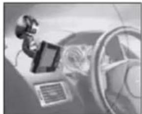
1) Before mounting the monitor, clean the mounting surface well.
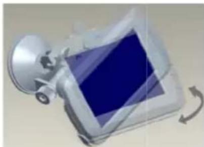
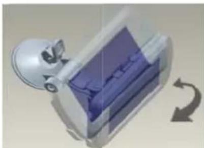
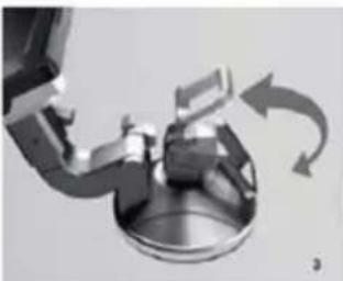
2) Position the suction mount to the smooth surface which suits your requirement.
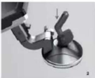
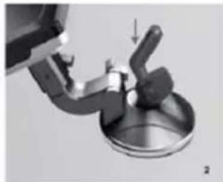
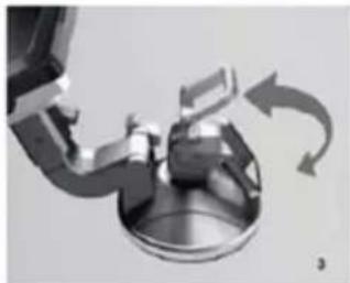
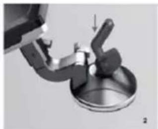
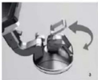
3) Press the suction cap against the smooth surface and press the lock down to attach and fix the mount to the surface.
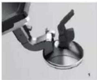
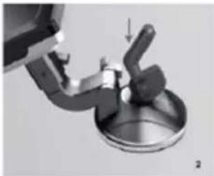
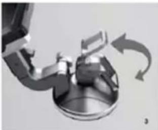
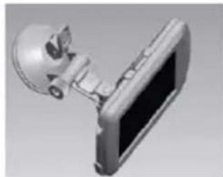
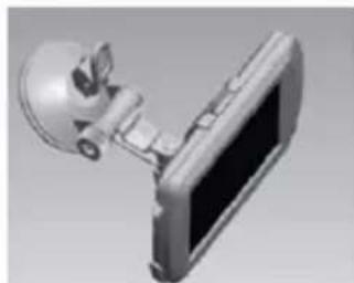
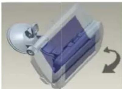
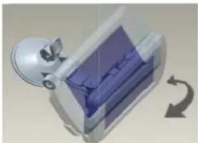
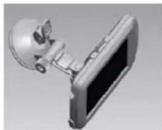
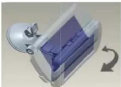
4) Adjust the mounting arms to suit your view angle to the monitor.
INSTALLATION
5) Route the power cable to the vehicle's cigarette lighter socket 12V/24V power outlet. The cable must not interfere with the safe operation of the vehicle.
6) Insert the small 12V/24V DC plug of the power cable into the right side of the monitor.
7) Plug the 12V/24V cigarette lighter plug into the vehicle's cigarette lighter socket.
8) To maximize the effectiveness of the suction mount, it is recommended that the application be performed under the following conditions:
• Surface temperature should be between 21 and 38 degrees Celsius.
- Application below 10 degrees should be avoided.
- Application should not occur in direct sunlight.
Mounting should be protected from exposure to direct sunlight for a period of 24 hours.
NOTENOTHER EXTREME BRIGHT LIGHT CONDITIONS, THE SCREEN IMAGE MAY TAKE A FEW SECONDS TO STABLIZE. PLEASE WAIT UNTIL THE IMAGE HAS STABLIZED BEFORE BACKING UP.
System testingSystem testing
1) Reattach the vehicle's negative battery cable.
2) Turn the ignition key to the accessory position, do not start the vehicle.
3) Engage the parking brake, and then put the shifter in the reverse position.
4) After testing the unit and you are satisfied with the route you have chosen for the cabling, you must permanently install it.
5) Route all wires behind interior panels or under carpeting so they are hidden. Use supplied cable ties to neatly gather any excess wire.
OPERATION
Please always pair the monitor and camera before the 1st operation, please refer to below "Pairing" step.
There are 6 control buttons available for users to have their controls:
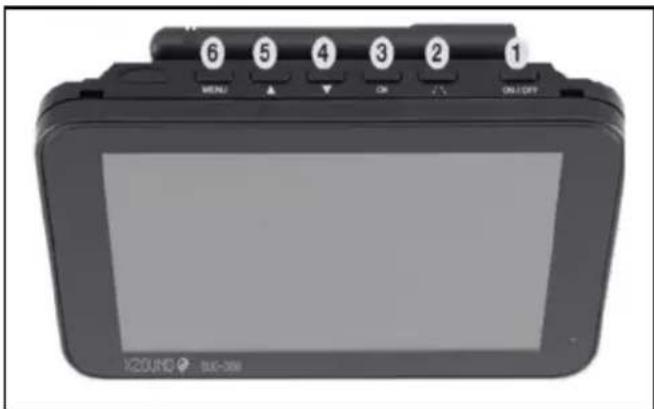
1) Power On / Off button
2) Parking guidelines display / back button
3) Enter button
4) Down button
5) Up / channels switching button
6) Menu button
OPERATION
Press to power on /turn off display. The display will be turn on by pressing the button. Long press for 3 second to shut down.
PARKING GUIDELINES DISPLAY /BACK BUTTON
Go back one level inside the menu control. Press to show Parking guideline. Press for 3 seconds until it starts flashing, use UP/DOWN button to adjust parking guideline display and then press Enter button to confirm.
ENTER BUTTON
Press to confirm selection inside the menu control.
DOWN BUTTON
Moving down for selection inside the menu control.
UP/CHANNELS SWITCHING BUTTON
Moving up for selection inside the menu control. Switching between channel 1 & 2.
MENU BUTTON
Press the Menu button to enter the menu screen as shown below: pairing, display & system info.
PairingPairing

Select the "Pairing" icon with the arrow buttons and press the Power button. Shortly after please press the rubber button on the bottom of camera until the signal is well received by the monitor and "OK" appears on the screen. The unit will work properly and will automatically pair by itself in the future operation. Press the menu button to exit the selection or it will automatically exit after 30s.
DisplayDisplay

Brightness, contrast, color, rotate settings. Press Up & Down button to choose. In this menu you can change brightness, contrast or colour of the picture. Chose the desired function with the arrow buttons, confirm by pressing the enter button and change the values with the arrow buttons.
System infoSystem info
Shows current monitor & camera system software versions.
TECHNICAL SPECIFICATIONS
Camera DRC5040
Operating voltage 12V / 24V DC
Current consumption <200mA(IRLED OFF) / <300mA(IRLED ON)
Image sensor 1/3" CMOS
Field of view 110°
Pixels 1920x1080FHD
Transmission & received frequency range 2.4G (ISM band)
RF transmission distance Up to 150m (unobstructed)
Monitor DRC5040
Input voltage 12V / 24V DC
Standby current <120mA
Operating current <250mA
LCD display screen size 5 inch / 12.7 cm
Effective Pixel 854x480
Operation temperature -10 - 50°C
Transmission & Received frequency range
2.4G (ISM band)
This model may be operated in EU countries.
ENVIRONMENTAL PROTECTION

Waste electrical products should not be disposed of with household waste. Please recycle where facilities exist. Check with your local authority or retailer for recycling advice.
WARRANTY
Pro-User Electronics warrants this product fo a period of 2 years from the date of purchase to the original purchaser. Warranty is not transferable. Warranty covers defect against workmanship and materials only. To obtain warranty service, please return the unit to the place of purchase or authorized Pro-User Electronics dealer together with your proof of purchase. The warranty is void if the product has been damaged or not used s described in this manual. Warranty is void if a non-authorized repair has been performed. Pro-User Electronics makes no other warranty expressed or implied. Pro-User Electronics is only responsible for repair or replacement (at Pro-User Electronics Discretion) of the defective product and is not responsible for any consequential damage or inconvenience caused by the defect.
Contact information:
Tradekar Benelux BV
+31(0)345470990
Ohmweg 1
Info@tradekar.com
4104 BM Culemborg The Netherlands
WWW.PRO-USER.COM

Important Safety Instructions P.10
Package contents P.11
Installation P.11
Operation P.15
Technical specifications P.17
Warranty P.17
EINLEITUNG
MONTAGE
MONTAGE
INSTALLATIE
INSTALLATIE
INSTALLATION
INSTALLATION
Operation temperature
-10 - 50°C
This model may be operated in EU countries.
PROTECTION DE L'ENVIRONNEMENT

Information side contact:
Tradekar Benelux BV
+31(0)345470990
Ohmweg 1
Info@tradekar.com
Pro-User Electronics is part of
4104 BM Culemborg
Tradekar House of Leisure Brands
The Netherlands

- CONTENTS
- INTRODUCTION
- IMPORTANT SAFETY INSTRUCTIONS
- PACKAGE CONTENTS
- INSTALLATION
- CAMERA INSTALLATIONCAMERA INSTALLATION
- OPERATION
- PARKING GUIDELINES DISPLAY /BACK BUTTON
- ENTER BUTTON
- DOWN BUTTON
- UP/CHANNELS SWITCHING BUTTON
- MENU BUTTON
- PAIRINGPAIRING
- DISPLAYDISPLAY
- SYSTEM INFOSYSTEM INFO
- TECHNICAL SPECIFICATIONS
- CAMERA DRC5040
- MONITOR DRC5040
- ENVIRONMENTAL PROTECTION
- WARRANTY
- CONTACT INFORMATION
- EINLEITUNG
- MONTAGE
- INSTALLATIE
- PROTECTION DE L'ENVIRONNEMENT
- INFORMATION SIDE CONTACT
Brand : Pro-User
Model : DRC5040
Category : Dashcam