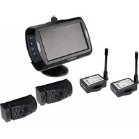
DRC4310DC - Dashcam Pro-User - Free user manual and instructions
Find the device manual for free DRC4310DC Pro-User in PDF.
| Product type | Dashcam with wireless rear view camera |
| Brand | Pro-User |
| Model | DRC4310DC |
| Camera power supply | 10-30 V DC |
| Monitor power supply | 10-30 V DC |
| Camera power consumption | ≤ 220 mA (12 V) / ≤ 110 mA (24 V) |
| Monitor power consumption (operating) | ≤ 350 mA (12 V) / ≤ 170 mA (24 V) |
| Monitor power consumption (standby) | ≤ 5 mA (battery charged) |
| Screen | 4.3 inch TFT, resolution 480x272 |
| Dashcam video resolution | Up to 1920x1080 (Full HD) |
| Dashcam photo resolution | Up to 12 MP (interpolated) |
| Rear view camera resolution | 640x480 |
| Transmission frequency | 2.4 GHz (ISM band) |
| Maximum range | 25 m (open field) |
| Storage | MicroSD/TF card max 32 GB, class 4 or higher (not included) |
| Built-in battery | Li-Po for video backup |
| Night vision | IR LED (850 nm) |
| Shock detection (G-sensor) | Yes, adjustable (2G/4G/8G) |
| Loop recording | Yes, adjustable duration (1/2/3/5/10 min) |
| Time stamp | Yes |
| Guidelines | Yes, switchable |
| Built-in microphone | Yes, enable/disable via menu |
| Operating temperature | -10 °C to +45 °C |
| Warranty | 2 years |
| Maintenance | Clean with a dry cloth; no user-serviceable parts |
Frequently Asked Questions - DRC4310DC Pro-User
User questions about DRC4310DC Pro-User
0 question about this device. Answer the ones you know or ask your own.
Ask a new question about this device
Download the instructions for your Dashcam in PDF format for free! Find your manual DRC4310DC - Pro-User and take your electronic device back in hand. On this page are published all the documents necessary for the use of your device. DRC4310DC by Pro-User.
USER MANUAL DRC4310DC Pro-User
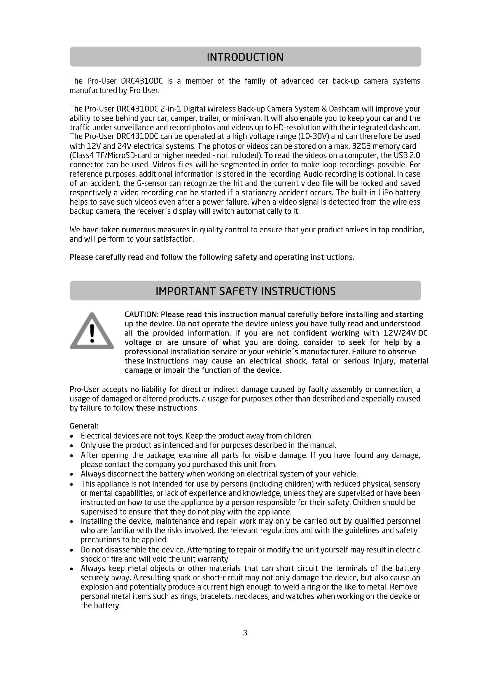
The Pro-User DRC4310DC is a member of the family of advanced car back-up camera systems manufactured by Pro User.
The Pro-User DRC4310DC 2-in-1 Digital Wireless Back-up Camera System & Dashcam will improve your ability to see behind your car, camper, trailer, or mini-van. It will also enable you to keep your car and the traffic under surveillance and record photos and videos up to HD-resolution with the integrated dashcam. The Pro-User DRC4310DC can be operated at a high voltage range (10-30V) and can therefore be used with 12V and 24V electrical systems. The photos or videos can be stored on a max. 32GB memory card (Class4 TF/MicroSD-card or higher needed - not included). To read the videos on a computer, the USB 2.0 connector can be used. Videos-files will be segmented in order to make loop recordings possible. For reference purposes, additional information is stored in the recording. Audio recording is optional. In case of an accident, the G-sensor can recognize the hit and the current video file will be locked and saved respectively a video recording can be started if a stationary accident occurs. The built-in LiPo battery helps to save such videos even after a power failure. When a video signal is detected from the wireless backup camera, the receiver's display will switch automatically to it.
We have taken numerous measures in quality control to ensure that your product arrives in top condition, and will perform to your satisfaction.
Please carefully read and follow the following safety and operating instructions.
IMPORTANT SAFETY INSTRUCTIONS

CAUTION: Please read this instruction manual carefully before installing and starting up the device. Do not operate the device unless you have fully read and understood all the provided information. If you are not confident working with 12V/24V DC voltage or are unsure of what you are doing, consider to seek for help by a professional installation service or your vehicle's manufacturer. Failure to observe these instructions may cause an electrical shock, fatal or serious injury, material damage or impair the function of the device.
Pro-User accepts no liability for direct or indirect damage caused by faulty assembly or connection, a usage of damaged or altered products, a usage for purposes other than described and especially caused by failure to follow these instructions.
General:
• Electrical devices are not toys. Keep the product away from children.
- Only use the product as intended and for purposes described in the manual.
- After opening the package, examine all parts for visible damage. If you have found any damage, please contact the company you purchased this unit from.
• Always disconnect the battery when working on electrical system of your vehicle.
- This appliance is not intended for use by persons (including children) with reduced physical, sensory or mental capabilities, or lack of experience and knowledge, unless they are supervised or have been instructed on how to use the appliance by a person responsible for their safety. Children should be supervised to ensure that they do not play with the appliance.
- Installing the device, maintenance and repair work may only be carried out by qualified personnel who are familiar with the risks involved, the relevant regulations and with the guidelines and safety precautions to be applied.
- Do not disassemble the device. Attempting to repair or modify the unit yourself may result in electric shock or fire and will void the unit warranty.
- Always keep metal objects or other materials that can short circuit the terminals of the battery securely away. A resulting spark or short-circuit may not only damage the device, but also cause an explosion and potentially produce a current high enough to weld a ring or the like to metal. Remove personal metal items such as rings, bracelets, necklaces, and watches when working on the device or the battery.
Working with Batteries
- Batteries can store large amounts of energy and improper handling can be dangerous
- Keep children away from batteries and acid.
- Avoid getting electrolyte on your skin or clothes. It is acidic and can cause burns. If battery acid contacts skin or clothing, wash immediately with water. Baking soda neutralizes lead acid battery electrolyte. If electrolyte gets into your eyes, immediately flood your eyes with running cold water for at least 20 minutes and get medical attention immediately. Eye protection is therefore recommended.
- Always keep metal objects or other materials that can short circuit the terminals of the battery securely away.
- Power-off the device before making or breaking the connections to the battery.
- Observe technical instructions of the seller or the manufacturer of your battery
- Check if all connections are tight and clean. Loose or dirty connections could result in overheating, electrical sparks and fire. Use terminal grease where required.
- Never smoke or allow a spark or flame in vicinity of the battery.
- Never try to charge a damaged or frozen battery.
- Read your car's owner's manual. Some vehicle manufacturers may have special requirements before disconnecting the vehicle's battery (e.g. fuses that have to be removed or certain security demands).
Electrical Cables
- If cables have to be fed through metal holes or other walls with sharp edges, use ducts or cable bushings to prevent damage.
- Do not lay cables which are loose or bent next to electrically conductive material (metal).
- Do not pull on the cables.
Interference
This device is free from interferences coming from Bluetooth, cell phones, Wi-Fi routers, power lines and other various electrical equipment.

Observe the relevant regulations and directives of your country!
Please always observe your local road traffic regulations and applicable privacy protection laws. Please make sure that it is allowed to use this device, especially the dashcam, in the country you are using it. Please do not record the privacy of individuals at any time and do not intend presenting the videos made to third parties or the public.
GENERAL INSTRUCTIONS
Intended use
The Pro-User 2-in-1 Digital Wireless Back-up Camera System & Dashcam is intended to be used as a back-up camera to improve the ability to see behind a car, camper, trailer, or mini-van. It also enables the owner to keep a car and the traffic under surveillance with photo and video recordings made with the integrated dashcam.
Maintenance
The unit itself is maintenance-free. From time to time, make sure all cable connections are clean and tight. If necessary, clean the unit with care, using a dry cloth. Don't try to open the body casing. There are no user-serviceable parts inside. Damage due to improper use, modifications or attempted repairs lead to the exclusion of liability and the loss of warranty. If the unit is damaged, the appliance must be discarded. Cleaning and user maintenance shall not be made by children.
Packaging materials
To avoid danger of suffocation, do not let children play with foils or other packaging materials. Remove all protective coverings before putting the device in operation.
Storage
When not in use, store the device in a dry environment. Store the device in a safe place out of the reach of children. Protect the unit from direct sunlight, heat and moisture.
SCOPE OF DELIVERY
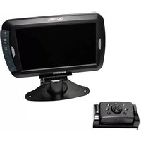
- Monitor with suction cup

natural_image
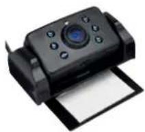
Black handheld electronic device with a screen and antenna, no visible text or symbols on the device body.- Camera with mounting plate
natural_image
Black handheld camera with control panel and paper sheet (no visible text or symbols)- USB Cable

- Monitor Power Cable
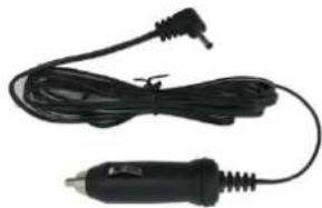
natural_image
Black and white photo of a handheld electric shaver with a terminal connector (no text or symbols visible)FRONT:
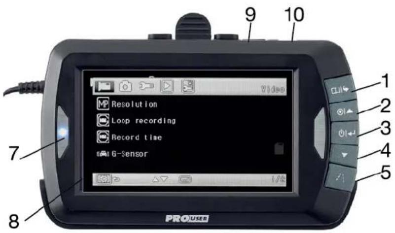
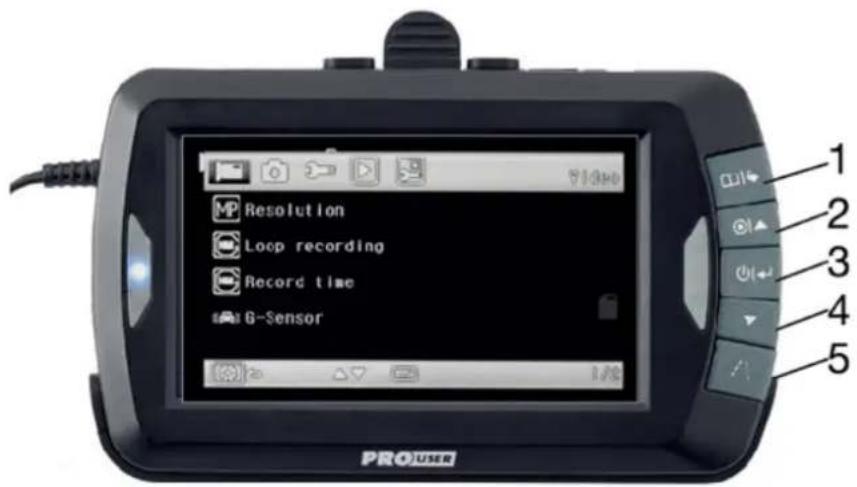
text_image
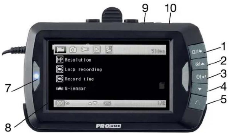
PROUSER 7 8 9 10 1 2 3 4 5| Item | Description |
| 1 | Menu / Setup |
| 2 | Video Recording / UP ▲ |
| 3 | Power / Enter |
| 4 | Photo / DOWN ▼ |
| 5 | Guideline / Lock Video / BACK |
| 7 | Blue LED |
| 8 | LCD-Screen |
| 9 | TF-card (microSD) slot |
| 10 | Micro-USB-Socket |
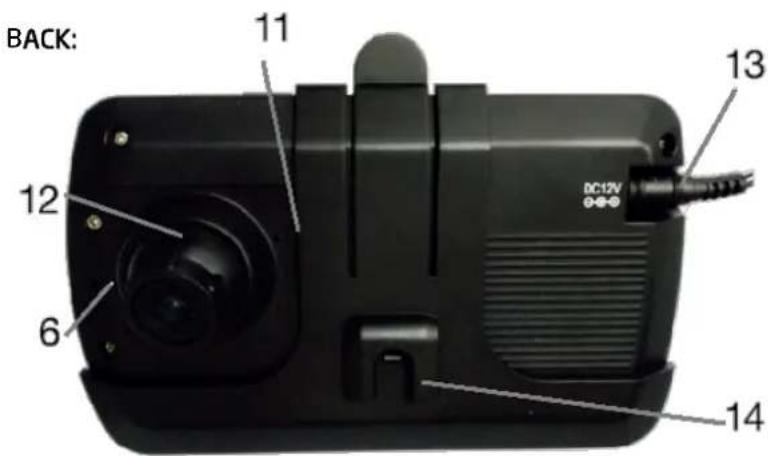
text_image
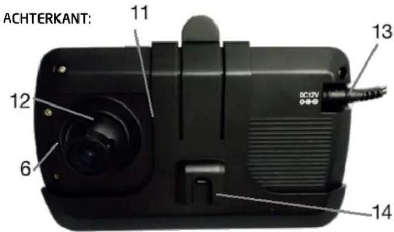
BACK: 11 12 6 13 DC12V 14| Item | Description |
| 6 | Reset-Button |
| 11 | Built-in Microphone |
| 12 | CMOS Camera (dashcam) |
| 13 | Power Input (DC 12V) |
| 14 | Bracket |
BACK-UP-CAMERA:
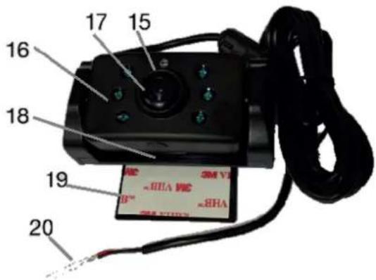
text_image
16 17 15 18 19 20 SM V1 ~RHA V1 B™ ~RHA SM V2| Item | Description |
| 15 | Brightness Sensor |
| 16 | IR-LEDs (nightview) |
| 17 | CMOS camera |
| 18 | Pairing-button |
| 19 | 3M Mounting Tape |
| 20 | Power Input (DC 12V) |
INSTALLATION
These instructions do not apply to all vehicles. They are only meant as a general guide due to the number of different makes & models. For vehicle-specific questions contact your vehicle's manufacturer.
Backup-Camera installation
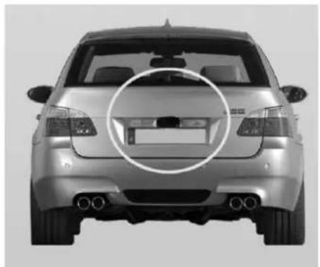
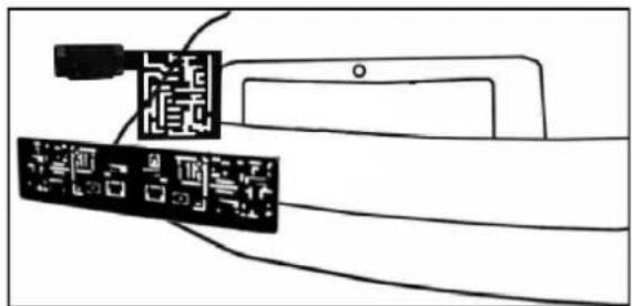
There are several ways to mount the camera on the back of your car. But the most convenient is to mount it near the license plate. Supplied is one mounting plate that can be fixed behind the license plate, and the mounting plate have been installed in the camera.
The camera itself is screwed on the mounting plate. The camera is tiltable, camera angle can be adjusted manually on vertical direction. Make sure that its field of view and detection are not obstructed.
natural_image
Front view of a silver sedan with a circular highlight on the side (no text or symbols visible)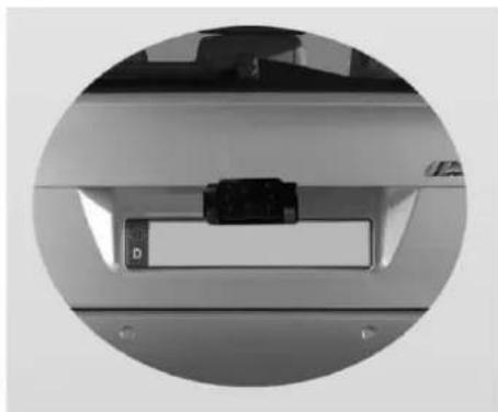
natural_image
Close-up of a mechanical component with a small rectangular component and mounting holes (no visible text or symbols)With some type of cars, it is not possible to mount the camera near the license plate. You may have to find another spot at the back of your car to mount it.
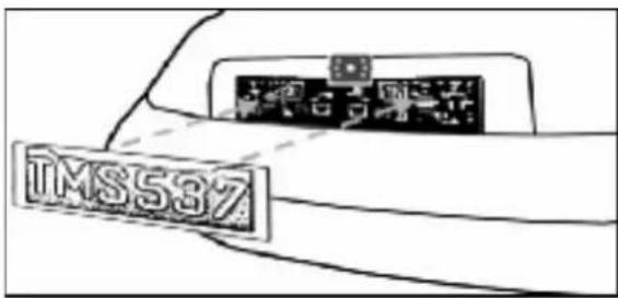
- Remove the rear license plate, and then loosen the license plate bolts/screws.
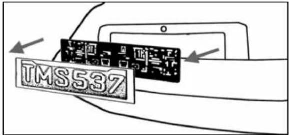
text_image
TMS537- Position the supplied mounting plates (with camera together) behind the license plate bracket. Secure both license plate bracket and mounting plates with the license plate bracket bolts/screws.
natural_image
Diagram showing two electronic components connected by wires, with no visible text or symbols- Mount the license plate on the license plate bracket.
text_image
TMS537-
Choose a routing path for the camera's power cable through the vehicle's body to the reverse light circuit. If in doubt, seek professional installation assistance.
-
Some vehicles may have a hole available to pass the wire through, such as where the license plate light is mounted, or you can drill a hole close to where the power cable is attached to the camera. Once you have chosen where the cable will enter the vehicle's body, remove the camera. If you are able to use an existing opening, skip the next two steps.
-
Before you drill a hole, you MUST CHECK and see WHAT IS BEHIND WHERE YOU ARE DRILLING. If there are any vehicle components, such as electrical parts or fuel system components behind where you are drilling, you must take whatever precaution is necessary not to damage them. Remove the license plate and camera before drilling.
-
After you have drilled the hole, insert the supplied grommet, then pass the camera cables through the grommet into the vehicle. You must use the grommet to prevent the metal edge of the hole from cutting the camera cable.
-
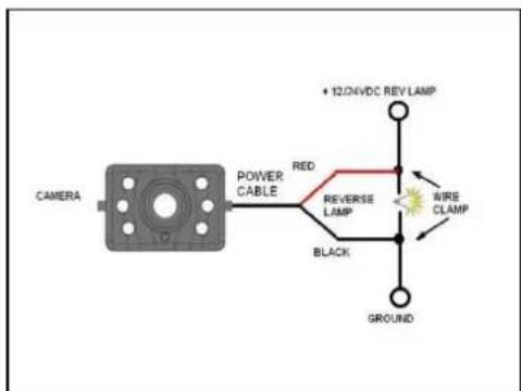
Next, you'll need to find the vehicle's reverse lights. Turn the vehicle's ignition key to the accessory position, engage the parking brake and put the car in reverse. Look at the vehicle's tail lights to see where the reverse lights are located, they are the white lights. To locate the reverse light's 12V/24V + wire it will be necessary to gain access to the rear of the vehicle's tail light. For help locating the vehicle's reverse light circuit contact your vehicle's manufacturer for vehicle specific wiring diagrams.
-
Once you have located the reverse light circuit you will have to route the camera cable to that location. You must securely fasten the power cable to prevent it from being caught on any vehicle component such as the trunk hinge. Never route the cable on the outside of the vehicle!
The reverse light sockets on most vehicles have two wires connected to them. Usually the negative wire is black and the positive wire is a coloured wire. If you are uncertain about the wiring, you can use a 12V/24V multimeter available at most auto parts stores to determine which is the positive wire. Follow the manufacturer's instructions for the safe use of the multimeter.
text_image
CAMERA POWER CABLE RED REVERSE LAMP BLACK + 12/4VDC REV LAMP WIRE CLAMP GROUND-
After determining which wire is the positive and which is the negative, turn off the ignition key, then remove the battery's negative cable.
-
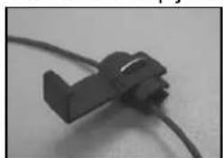
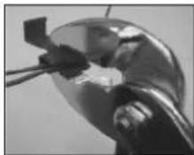
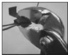
Splice the red wire using the supplied in-line wire connectors to the reverse light's positive (+) wire. Use a set of slip joint pliers to squeeze the TAP and insure good connection.
natural_image
Close-up of a black mechanical component with a curved cable (no visible text or symbols)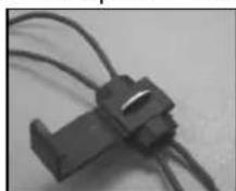

-
Next, splice the black wire of the camera power cable to the reverse light's negative (-) wire or ground.
-
Replace the reverse light bulb, and then re-install the light socket. Secure all the wires with cable ties or electrical tape.
-
Re-attach the negative battery cable to the battery.
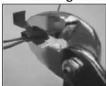
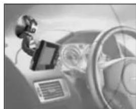
Monitor Installation
When choosing a location to mount the monitor, make sure the monitor is in an area that will not obstruct your vision while driving.
natural_image
Close-up of a robotic arm interacting with a steering wheel and dashboard (no visible text or symbols)-
Before mounting the monitor, clean the mounting surface well.
-
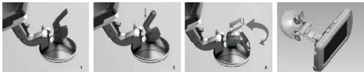
Position the suction mount to the smooth surface which suits your requirement.
-
Press the suction cap against the smooth surface and press the lock down to attach and fix the mount to the surface.
natural_image
Four-panel diagram showing mechanical assembly steps: disassembly, rotation, and final assembly (no text or symbols)-
Snap in the monitor to the suction mount.
-
Adjust the mounting arms to suit your view angle to the monitor and tighten the screws on the mount to fix the position.
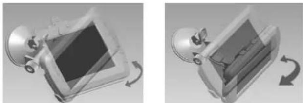
natural_image
Two grayscale diagrams showing a car interior with a rectangular frame and a curved arrow indicating rotation (no text or symbols)-
Route the power cable to the vehicle's cigarette lighter socket 12V/24V power outlet. The cable must not interfere with the safe operation of the vehicle.
-
Insert the small 12V/24V DC plug of the power cable into the right side of the monitor.
-
Plug the 12V/24V cigarette lighter plug into the vehicle's cigarette lighter socket.
To maximize the effectiveness of the suction mount, it is recommended that the application be performed under the following conditions:
• Surface temperature should be between 21 and 38 degrees Celsius.
• Application below 10 degrees should be avoided.
• Application should not occur in direct sunlight.
Mounting should be protected from exposure to direct sunlight for a period of 24 hours.
Please always pair the monitor and camera before the 1^st operation.
Testing the back-up camera system after Installation:
- Check if the vehicle's negative battery cable (ground) has been reattached.
- Turn the ignition key to the accessory position - do not start the vehicle
- Engage the parking brake, and put the vehicle's shifter in the reverse position (backup lights are lit). If not already done: Please pair your camera to the monitor (as described in paragraph Pairing). The System should activate itself. If not, press the Power-button on the Monitor
- After testing (and re-adjusting if needed) the unit, all cabling should be installed permanently: Route all wires behind interior panels or under carpeting. Use the supplied cable ties to keep excess wires neat and compact.
NOTE: UNDER EXTREME BRIGHT LIGHT CONDITIONS, THE SCREEN IMAGE MAY TAKE A FEW SECONDS TO STABILIZE. PLEASE WAIT UNTIL THE IMAGE HAS STABILIZED BEFORE BACKING UP.
Pairing:
Enter the Menu by pressing the MENU-button and select the "Pair" icon with the arrow buttons and press ENTER. Shortly after, press the rubber button on the bottom of the camera until the signal is received by the monitor.
Backup-Camera-mode: If the device is in standby, press the POWER button to supply power to the monitor. The picture on the monitor will automatically turn on or switch from another mode to Backup-Camera-mode, when the vehicle is in reverse gear (monitor receives video signal from backup-camera).
Orientation:
In the Menu "Picture direction" you can change the orientation of the picture. These different views allow you to mount the camera and monitor in any position with keeping the right picture on the monitor. Simply enter the "Picture direction" menu by choosing it and pressing the Power button. The orientation of the picture will change every time pressing the Power button. To save the settings and exit the screen please press the menu button.
OPERATION (Dashcam)
To make use of the dashcam a memory card has to be installed.
(max. 32GB memory card, Class4 TF/MicroSD-card or higher is needed - not included)
text_image
Resolution Loop recording Record time G-Sensor PROUSER1 MENU / SETUP
Press the MENU-button to enter the menu screen: Available options are: Video Settings, Photo Settings, System Settings, Playback and Pairing Settings. Select the settings-menu you want to edit with the arrow buttons ▲ ▼ and confirm your selection with the ENTER-button (3).
Function 1: in any settings-menu: selection of the above item
Function 2: when playing a video: fast reverse of the current video
Function 3: in Video-mode: start or stop a recording
Function 4: in Photo-mode: switch to Video-mode
3. POWER / ENTER
Function 1: in any settings-menu: confirm your selection
Function 2: when playing a video: pause the current video
Function 3: in Photo-mode: take a photo
4. PHOTO MODE / DOWN ▼
Function 1: in any settings-menu: selection of the item below
Function 2: when playing a video: fast forward the current video
Function 3: in Video-mode: switch to Photo-mode
Function 4: in Photo-mode: take a photo
5. GUIDELINE / BACK / LOCK VIDEO -button
Function 1: in any settings-menu: return to the previous page or quit
Function 2: during video recording: lock and protect the current video.
Function 3: in Back-Up-Camera-mode: activate guidelines;
Guidelines
This camera system has the option to show distance-guidelines on the display. This helps you to visually see the distance between the objects behind your car. By pressing the guideline button in back-up-camera-mode, you can switch this option on and off.
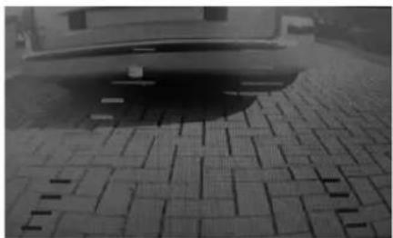
natural_image
Black-and-white photo of a car parked on a paved pavement with a grid-patterned pavement (no visible text or symbols)6. RESET (small button on the backside of the unit)
If the system has frozen or you want to reset the unit to factory settings, press the RESET-button with a clip or a toothpick.
Taking Photos and Videos
- If the device is in standby, press the UP or DOWN-button to switch between Video-mode and Photo-mode.
- In Video-mode, press the UP -button to record a video
- In Photo-mode, press the DOWN-button to take a photo.
System Menu and System Settings
- Press the Menu-button to enter the menu screen.
- Select the settings-menu you want to edit with the UP/DOWN buttons ▲▼ and confirm your selection with the ENTER-button. Press the BACK-button to return to the previous page or quit.
Video-Settings
Resolution: The higher the resolution, the better is the picture quality but also memory usage.
Possible selections are:
- VGA 640 x 480
- WVGA 848 x 480
- HD 720p 1280 x 720
Loop Recording: Off / On
If Loop-Recording is turned on, the last video-file will be overwritten with the current.
Record time:
In this setting, you can define, how long a video file shall be recorded.
Possible selections are: 1 Minute / 2 Minutes / 3 Minutes / 5 Minutes / 10 Minutes
G-Sensor:
Possible selections are: Off / 2G / 4G / 8G
If activated, the device can notice an impact or a crash and automatically lock the current video file and store it. This mechanism prevents the file from being overwritten.
Since the sensor might be even triggered on bumpy roads, it's sensitivity can be adjusted to improve the detection accuracy and to avoid false positives (and increased memory usage).
A current recording can also be locked manually by pressing the BACK-button.
Note: Since locked files may need a large amount of storage capacity, it is recommended to check regularly if not-needed files can be deleted.
G-Sensor record
Possible selections are: Off / 2G / 4G / 8G
If activated, the device will automatically start a video recording and also protect this file from being overwritten when the g-sensor is triggered in standby-mode (e.g. when your vehicle is parked and got hit). Sensibility can also be adjusted.
Microphone: Off / On
Turn audio in video recordings on or off.
Power on record: Off / On
Automatically start a recording when the device is powered on.
Camera-Settings
In this settings-menu, you may adjust the photo quality:
Resolution: VGA, 1.3M, 2M, 3M, 5M, 8M, 10M, 12M
Exposure: from EV-2.0 up to EV+2.0
Sharpness: Strong / Normal / Soft
Quality: Fine / Normal / Economy
White Balance: Auto / Daylight / Cloudy / Tungsten
ISO: Auto / 100 / 200
Anti-Shaking: Off / On
Quality Review: This setting affect show long a photo is displayed after being taken.
Off / 2 Seconds / 5 Seconds
Setup-Settings
In this settings-menu, you can adjust general settings like time, date, language and energy saving settings, but also format your memory card, reset the device to default values or show the software version of the unit:
Date/Time: Select to adjust time and date.
Frequency: 50Hz / 60Hz
Screen Saver: Off / 3 Minutes / 5 Minutes / 10 Minutes
Auto power off: Off / 1 Minute / 3 Minutes
Language: English / 繁體中文 / 簡体中文 / 日本語 / Français/ Deutsch/ 한국어/ Italiano/
Version: Shows the software-version of the device.
Playback, lock, unlock or delete stored files
Browse saved files:
Press the MENU/SETUP-button and select the Playback-Icon.
Press the UP /DOWN buttons ▲ ▼ to browse stored files
Playback a file:
Select a file with the UP /DOWN buttons and press ENTER. Select PLAY and press ENTER to playback the file. During playing, press UP /DOWN buttons to fast-forward or reverse or press ENTER to pause.
Lock, unlock or delete a file:
Select a file with the UP /DOWN buttons and press ENTER.
Select PROTECT to lock or unlock a file.
Select DELETE to delete the current or all files.
USB-Mode
Please connect the device to your Personal Computer via the delivered USB cable and make sure a memory card is installed. The device will be recognized as a flash-drive and you can copy, move or delete your stored photo or video files.
TROUBLESHOOTING (backup-camera)
Some modern vehicles with a monitoring function of the reversing lights (signal monitoring via PWM Pulse Width Modulation and CAN of the vehicle, e.g. to detect a faulty light bulb or to regulate brightness) may produce interference to the image transmission or even cause a total loss of the wireless connection to the camera module.
In case your vehicle has this monitoring function, it might be necessary to implement one of the following measures to restore the full functionality of your backup camera system:
1. Implementation of a PWM signal filter
These commercially available filters are usually put between chassis ground (negative pole) and the positive power supply of the reversing light and the camera module. If you intend to use such a filter, please follow the manufacturer's instructions.
Common trade names are:
„Reverse Backup Camera Power Adapter Filter“ or
„Noise filter for pulsed reversing lights“
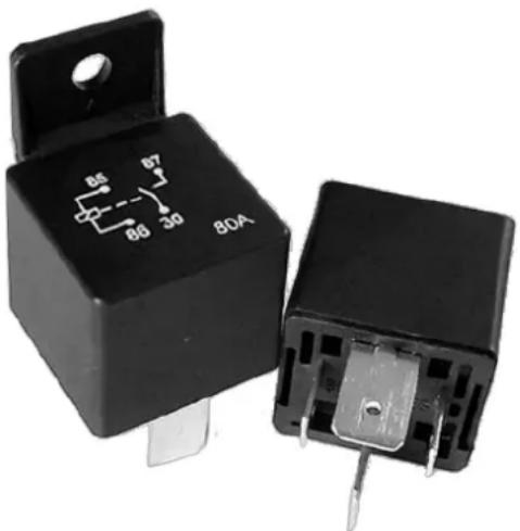
2. Usage of an automotive current relay
Another simple method to ensure the voltage supply of the camera module without an interfering PWM-signal is to make use of a conventional automotive relay. The power supply of the reversing light is used to trigger temporarily the relay (electromechanical switch), which connects the PWM-free "ignition plus" of the vehicle to the positive wire of the camera module.
| Contact | Description |
| 85 | chassis ground of the control current circuit(negative-wire of the reversing light and the camera module) |
| 86 | + positive wire of the control current circuit(looped through supply of the reversing light) |
| 87 | + positive wire to the camera module |
| 30 | + voltage supply of the vehicle(terminal 15 „ignition plus“alternatively: contact terminal 30 „from battery+ direct“) |
Picture: A conventional automotive relay with standardized contact terminals
natural_image
Two black automotive contactors with visible internal components and terminal pins (no text or symbols)TECHNICAL SPECIFICATIONS
Camera / Transmitter
| Operating Voltage | 10-30V DC |
| Current consumption | ≤ 220mA @12V ≤ 110mA @24V |
| Image sensor | CMOS |
| Resolution | 640x480 |
| Optical lens | 1.7mm / F2.0 |
| IR Emission Wavelength | 850nm |
| Transmission frequency | 2.4 GHz (ISM band)2409.75-2472.75MHz |
| Transmitting Power | ≤ 20dBm |
| RF transmission distance (open space) | 25m |
LCD monitor /Receiver
| Operation Voltage | 10-30V DC |
| Standby Current | ≤ 5mA (with full Battery) |
| Shutdown Current | <80 A (built-in battery) |
| Operation Current | ≤ 350 mA @12V ≤ 170mA @24V |
| LCD display screen size | 10.9cm / 4.3 inch TFT |
| Resolution | 480x272 |
| Connectivity | - USB 2.0 Support- Micro-SD Card:>Class 4>32 GB |
Other
Dashboard Camera Video Resolution Up to HD 1280x720
Operation temperature -10 to +45 degrees Celsius


10R-05.2421
This model may be operated in EU countries.
ENVIRONMENTAL PROTECTION

The product is classed as Electrical or Electronic Equipment and should not be disposed of with other household or commercial waste at the end of its working life. Please recycle where facilities exist. Ask your local authority or retailer for recycling advice.
WARRANTY
Pro-User warrants this product for a period of 2 years from the date of purchase to the original purchaser. Warranty is not transferable. Warranty covers defect against workmanship and materials only. To obtain warranty service, please return the unit to the place of purchase or authorized Pro-User dealer together with your proof of purchase. The warranty is void if the product has been damaged or not used as described in this manual. Warranty is void if a non-authorized repair has been performed. Pro-User makes no other warranty expressed or implied. Pro-User is only responsible for repair or replacement (at Pro-Users' Discretion) of the defective product and is not responsible for any consequential damage or inconvenience caused by the defect.
EINLEITUNG
natural_image
Black handheld electronic device with a screen and control panel, mounted on a stand (no visible text or symbols)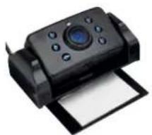
natural_image
Black handheld camera with control panel and paper sheet (no visible text or symbols)natural_image
Black and white photo of a handheld electric tool with wires (no text or symbols visible)VORDERSEITE:
text_image
PROUSER Resolution Loop recording Record time G-Sensor 1 2 3 4 5 7 8 9 10 VIDEOnatural_image
Front view of a silver car with visible license plate and exhaust pipes (no text or symbols)
natural_image
Close-up of a mechanical component with a small rectangular component and a label 'D' (no readable text or symbols)natural_image
Diagram showing two connected electronic components with circuit patterns, no text or symbols presentnatural_image
Close-up of a black plastic clip attached to a wire, no visible text or symbols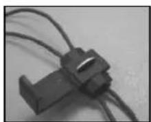
natural_image
Close-up of a black plastic connector with coiled wires (no visible text or symbols)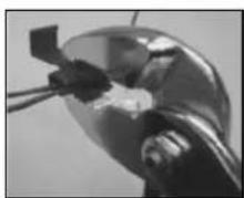
natural_image
Close-up of a mechanical component with a metallic head and internal components (no visible text or symbols)
natural_image
Close-up of a black rectangular electronic component with two wires (no visible text or symbols)natural_image
Close-up of a robotic arm interacting with a steering wheel (no visible text or symbols)natural_image
Close-up of a mechanical component with a metallic housing and lever mechanism (no visible text or symbols)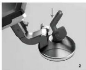
natural_image
Mechanical assembly diagram showing a valve or lever interacting with a circular base (no text or symbols visible)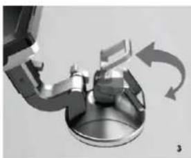
natural_image
Mechanical assembly diagram showing rotating components with curved arrows indicating motion (no text or symbols)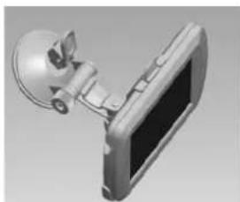
natural_image
3D rendering of a mechanical device with a spherical component and a screen (no text or symbols visible)natural_image
3D rendered image of a mechanical device with a square component and rotating arrow (no text or symbols)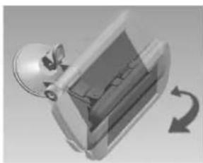
natural_image
3D illustration of a mechanical component with a rotating arrow indicating rotation (no text or symbols)text_image
Resolution Loop recording Record time G-Sensor PROUSER1 MENU / SETUP
natural_image
Black-and-white photo of a car parked on a paved pavement with tiled flooring (no visible text or symbols)Microphone: An/Aus (Off / On)
Power on record: An/Aus (Off / On)
Qualität (Quality): Fein/Normal/Economy (Fine / Normal / Economy)
Frequenz (Frequency): 50Hz / 60Hz
natural_image
Two black electrical relay components with visible pinout and mounting holes (no text or symbols)natural_image
Black handheld electronic device with a screen and control panel, no visible text or symbols on the device body.natural_image
Black handheld electronic device with a circular lens and paper sheet (no visible text or symbols)- USB kabel

natural_image
Black electric heating tool with coiled cable and terminal connector (no text or symbols visible)VOORKANT:

text_image
PROUSER Resolution Loop recording Record time G-Sensor 1 2 3 4 5 7 8 9 10 VIDEO| Nr | Omschrijving |
| 1 | Menu / Setup |
| 2 | Video Recording / UP ▲ |
| 3 | Power / Enter |
| 4 | Photo / DOWN ▼ |
| 5 | Guidelines / Lock Video / BACK |
| 7 | Blauw LED |
| 8 | LCD-display |
| 9 | TF-kaart (microSD) slot |
| 10 | Micro-USB-ingang |
text_image
ACHTERKANT: 11 12 6 13 DC12V 14Nr Omschrijving
6 Reset-knop
natural_image
Front view of a silver sedan car with visible license plate and side exhaust pipes (no text or symbols)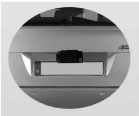
natural_image
Close-up of a mechanical component or bracket with a small rectangular object inside, enclosed in a circular frame (no visible text or symbols)natural_image
Diagram showing a device connected to a screen with a circuit board, no text or symbols presentnatural_image
Close-up of a black plastic clip attached to a wire (no text or symbols visible)
natural_image
Close-up of a car's dashboard and steering wheel with a mounted sensor device (no visible text or symbols)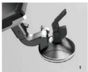
natural_image
Close-up of a mechanical component with a circular base and lever mechanism (no visible text or symbols)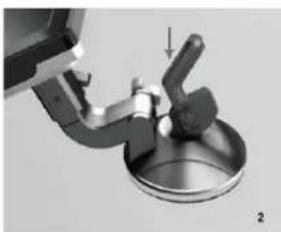
natural_image
Mechanical assembly diagram showing a lever pressing down on a metal component (no text or symbols visible)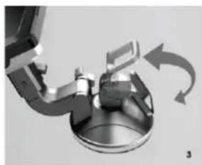
natural_image
Mechanical assembly diagram showing a rotating component with curved arrows indicating motion (no text or symbols)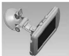
natural_image
3D rendering of a mechanical device with a spherical component attached to a screen (no visible text or symbols)natural_image
Illustration of a computer monitor with a scroll wheel and directional arrow (no text or symbols)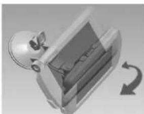
natural_image
3D rendered mechanical component with a rotating arrow indicating rotation (no text or symbols)WERKING (Back-up Camera))
text_image
Resolution Loop recording Record time G-Sensor PROUSER1 MENU/SET UP
natural_image
Black-and-white photo of a car parked on a paved surface with tiled pavement (no visible text or symbols)natural_image
Two black electronic components with internal circuit symbols and terminal pins, no readable text or labels present.TECHNISCHE SPECIFICATIES
Camera / zender
| Voedingsspanning | 10-30V DC |
| Stroomverbruik | ≤ 220mA @12V ≤ 110mA @24V |
| Beeld sensor | CMOS |
| Resolutie | 640x480 |
| Lens | 1.7mm / F2.0 |
| IR golflengte | 850nm |
| Zendfrequentie | 2.4 GHz (ISM Band)2409.75-2472.75MHz ≤ 20dBm |
| RF zendafstand (open ruimte) | 25m |
LCD monitor/ontvanger
| Voedingsspanning | 10-30V DC |
| Stroomverbruik "standby" | ≤ 5mA (met volle accu) |
| Stroomverbruik "shutdown" | <80 A (accu) |
| Stroomverbruik operationeel | ≤ 350 mA @12V ≤ 170mA @24V |
| LCD display schermgrote | 10.9cm / 4.3 inch TFT |
| Resolutie | 480x272 |
| Connectiviteit | - USB 2.0 support- Micro-SD Card:>Class 4>32 GB |
Overige
natural_image
Black PAGC GPS monitor with control panel and display (no visible text or symbols)
natural_image
Black handheld camera with control panel and paper sheet (no visible text or symbols)- Câble USB

natural_image
Black electric soldering iron with coiled cable and terminal connector (no text or symbols visible)PANNEAU AVANT :

text_image
PROUSER Resolution Loop recording Record time G-Sensor 1/2 7 8 9 10text_image
16 17 15 18 19 20 M V1 B" M V2 M V3natural_image
Front view of a silver sedan car with visible license plate and side exhaust pipes (no text or symbols)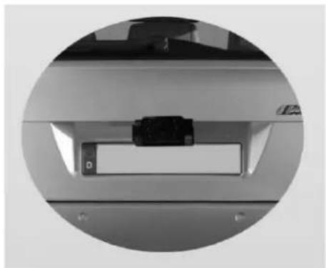
natural_image
Close-up of a mechanical component with a black rectangular slot and a small labeled part, enclosed in a circular frame (no visible text or symbols)natural_image
Diagram showing two electronic components connected to a device (no text or symbols visible)natural_image
Close-up of a black plastic connector with a curved cable (no text or symbols visible)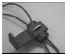
natural_image
Close-up of a metallic mechanical component with a small rectangular component inserted (no visible text or symbols)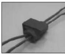
natural_image
Close-up of a black rectangular electronic component with two wires (no visible text or symbols)natural_image
Close-up of a robotic arm interacting with a steering wheel and dashboard (no visible text or symbols)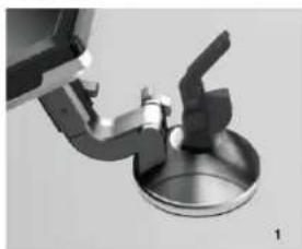
natural_image
Close-up of a mechanical component with a metallic housing and lever mechanism (no visible text or symbols)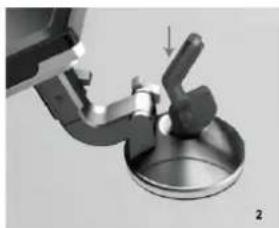
natural_image
Mechanical assembly diagram showing a valve or lever interacting with a circular base (no text or symbols visible)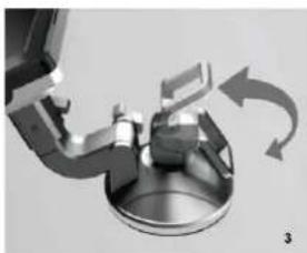
natural_image
Mechanical assembly diagram showing rotating components with curved arrows indicating motion (no text or symbols)
natural_image
3D rendering of a wall-mounted device with a spherical sensor and screen (no text or symbols visible)natural_image
Illustration of a computer monitor with a scroll wheel and circular arrow indicating rotation (no text or symbols)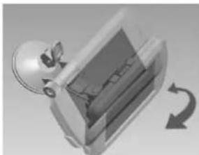
natural_image
3D rendered mechanical component with a rotating arrow indicating rotation (no text or symbols)text_image
Resolution Loop recording Record time G-Sensor PROUSER1 MENU / SETUP
natural_image
Black-and-white photo of a car parked on a paved surface with visible pavement patterns (no text or symbols)Netteté : Haute/Normale/Douce (Forte / Normale / Douce)
natural_image
Two black automotive contactors with visible terminal markings and mounting holes (no text or symbols on the main body)EU – Declaration of Conformity
We herewith confirm that the appliance as detailed below complies with the mentioned directives.
Artikelbezeichnung:
Article description:
Digital Wireless Back-up Camera System & Dashcam
Artikelnummer:
Article number:
20150
Typenbezeichnung:
Type:
DRC4310DC
Firmenanschrift:
Company address:
Pro-User Europe GmbH, Seestrasse 19, 83253 Rimsting, Germany
Governing EU-directives / directives CE concernées:

Electromagnetic compatibility (EMC)
2014/30/EU

Low voltage directive
2014/35/EU

- Funkanlagen und
Radio and Telecommunication Terminal Equipment
R&TTE 1999/5/EC

- RoHS-Richtlinie
RoHS Directive
2011/65/EC (method EN62321)
harmonised EN-Standards
The article complies with the standards as mentioned below which are necessary to obtain the CE-symbol:
| zu 1.EN61000-6-1:2007EN61000-6-3:2007+A1:2011EN55022:2010+AC2011EN55024:2010 | zu 2.EN60950-1:2006+A11:2009+A1:2010+A12:2011+A2:2013 |
| Zu 3.EN 300 440-1 V1.6.1:2010EN 300 440-2 V1.4.1:2010EN 301 489-1 V1.9.2:2011EN 301 489-3 V1.4.1:2002 | Zu 4.IEC62231:2008 |
Signature & Company Stamp

Position Managing Director
Geschäftsführer
Ausstellungdatum:
Date of issue
05.06.2019
© Pro-User Europe

text_image
PROUSER®Germany www.pro-user.com