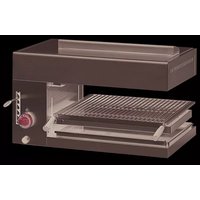
SAG660 - Gas Heating MBM - Free user manual and instructions
Find the device manual for free SAG660 MBM in PDF.


| Product type | Gas heater (salamander) |
| Brand | MBM |
| Model | SAG660 |
| Category | II2E+3+ |
| Year of manufacture | 1995 |
| Nominal heat output | 7.4 kW |
| Minimum heat output | 4.5 kW |
| Type of construction | A (without flue connection) |
| Supply pressure G20 | 20/25 mbar |
| Supply pressure G30 | 28-30/37 mbar |
| Consumption G20 | 0.78 m³/h |
| Consumption G30 | 0.58 kg/h |
| Gas connection | R1/2"G (ISO 7-1) |
| Weight | 32 kg |
| Material | Stainless steel |
| Number of feet | 4 height-adjustable feet |
| Ignition | Piezoelectric and manual |
| Functions | Grill and radiant cooking |
| Safety | Safety valve, thermocouple |
| Maintenance | Clean after cooling, avoid abrasive products |
| Spare parts | Available from the manufacturer |
Frequently Asked Questions - SAG660 MBM
User questions about SAG660 MBM
0 question about this device. Answer the ones you know or ask your own.
Ask a new question about this device
Download the instructions for your Gas Heating in PDF format for free! Find your manual SAG660 - MBM and take your electronic device back in hand. On this page are published all the documents necessary for the use of your device. SAG660 by MBM.
USER MANUAL SAG660 MBM
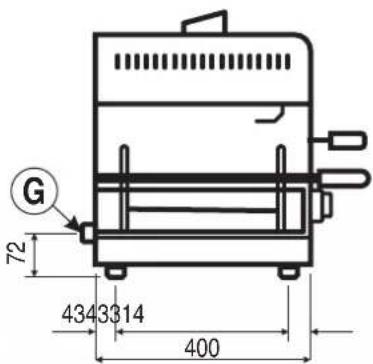


Attacco gas ø1/2"G
Gasanschluß ø 1/2"G
Gas connection ∅1/2"G
Gaz prise ø1/2"G
Installation diagram
natural_image
Simple line drawing of a rectangular frame with mounting flanges (no text or symbols)Stainless steel wall bracket
Diagram for drilling cement walls for the fastening of brackets
natural_image
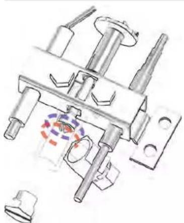
Technical illustration of a mechanical assembly with no visible text or symbolsRegolazione pilota
Regulating the pilot burner
Unit characteristics
These installation instructions refer to the salamander gas unit, Category II2H3+.
The self-adhesive polyesterdata plate, is affixed on the right side of the unit and provides the following information:
Model SG
Serial number: XXXXXX
Category: II2H3+
Year of construction: 1995
Nominal thermal capacity: 7,4 kW
Construction type: A
Test base: EN 203-1
Connection pressure: G 30 28-30/37 mbar
G 20 20 mbar
Consumption: G 30 0,58 kg/h
G 20 0,78 m ^3 /h
The supplementary plate is also made of self-adhesive polyester and is affixed near the data plate; it contains all information regarding the actual unit.
The unit is equipped with a 7.4 kW burner (minimum thermal capacity 4.5 kW).
The combustion chamber and burner are in stainless steel.
The unit is in stainless steel and fitted with 4 height-adjustable feet. The gas connection ramp complies with the (ISO 7-1) prescriptions and has a diameter of R1/2"G.
All fittings have metallic seals, guaranteed by the use of bicones. Gas pipes, from the ramp to the cock, are made of galvanized steel while those from the cock to the burner are made of copper.
Thermal capacity can be adjusted from maximum to minimum by means of the cock (fitted with valve) which is completely safe.
A pilot burner is used to ignite the main burner.
Location
- The unit must be installed in a well ventilated room, possibly underneath a hood.
- Only a qualified and authorized gas expert may install and service the unit, connect it to the gas mains, convert or adapt it to another type of gas or eliminate any faults.
Prior to installation you should obtain authorization from the local gas board to install the unit. - Prior to connecting the unit, install a cutoff cock upstream between the unit and the distribution network.
- The unit can be placed on a work surface or mounted on the wall (in this case the wall must be of a non flammable material). A minimum distance of 200 mm must be left all round the unit, away from any walls in flammable material or other adjacent equipment. If this distance is not complied with then insulation is essential, e.g. using tiles or a radiation protection on adjacent walls.
The distance recommended on the right side is 300 mm; this is necessary to allow for maintenance or repairs. - If the unit is wall mounted, use suitable brackets
available on request as an optional plus the protection plate. Make sure the wall is made of brick and not of a flammable material and make sure it can withstand a weight of approximately 32 kg.
The brackets are to be fixed to the wall in the following manner: drill holes in the wall following the installation diagram, use 4 steel wall bolts suitable for M6 screws (Fischer SLM6 or their equivalent) (fig.4).
Attention: The manufacturer shall not be held responsible for damage caused by negligence in following the operating and installation instructions or by improper use.
In addition, the manufacturer shall not be held responsible for connections that are not made in accordance with current laws.
Fire-fighting prescriptions must be strictly abided by!
Law provisions, technical regulations and norms
When installing the unit the following prescriptions must be complied with:
• The gas safety (installation & use) regulations of 1984
- The gas safety (installation & use) regulation (Amendment 1990)
- Local prescriptions, such as building standards and prescriptions concerning combustion
- Directives and regulations of the gas supply company and of the power supply company
• Health and safety at work etc. Act 1974 - The unit must only be installed in rooms where there is sufficient ventilation.
Technical data
Nozzle Table
| Nominal thermal Minimum thermal capacity capacity | |||
| Thermal capacity (kW) 7,4 4,5 | |||
| Connection | |||
| Natural gas H (Hi = 9,45kWh/ m3) m3/ h 0,78 0,47 LPG (Hi = 12,68 kWh/ kg) kg/ h 0,58 0,35 | |||
| nozzle in 1/100 mm | Pilot burner | No 0,35 | |
| Natural gas H 20mbar | Main burner | 205 | |
| Minimum | 200 | ||
| LPG 28-30/ 37mbar | Pilot burner | No 0,20 | |
| Main burner | 135 | ||
| Minimum | 125 | ||
| Primary air Natural gas 19mm | |||
| Distance "H" | LPG | 40mm | |
Gas connection
Prior to connecting the unit to the gas mains, check the data plate to see if the unit has been set and tested for the type of gas available.
If the gas type given on the data plate is not the same as that available, please refer to the paragraph "Conversion or Adaptation".
Connect up to the gas mains using metal pipes with a suitable diameter; install an approved cutoff cock between them.
If flexible pipes are used they must be in stainless steel according to the standard in force.
The connection ramp on the unit complies with the ISO 7-1 standard, and the thread is external. This ramp is at the rear of the unit on the right.
Only an authorized firm may connect the unit.
Once the unit has been installed, use operating pressure to check for leaks on the fittings; foamy substances would be ideal for this purpose as they do not cause corrosion, e.g. a leak finder spray.
Note: When checking for leaks do not use bare flames!
Evacuating burnt products
This unit belongs to construction type A therefore it
does not have to be connected to a flue.
Checking mains pressure
Operation is permitted with the thermal capacity deriving from the use of the correct nozzles and, of course, according to mains pressure, observing the following:
L.P.G.
Operation is permitted for mains pressure ranging between 20-25 and 35-45 mbar.
Operation is not permitted with mains pressure below 20-25 and 35-45 mbar.
If mains pressure on the installation site deviates from the above values or is not within the above pressure range, advise the installers and do not turn the unit on until the cause has been found and remedied.
NATURAL GAS H
Operation is permitted for mains pressure ranging between 17 and 25 mbar.
Operation is not permitted with mains pressure
below 17 and above 25 mbar.
If mains pressure on the installation site deviates from the above values or is not within the above pressure range, advise the gas board and do not turn the unit on until the cause has been found and remedied.
Read mains pressure with a gauge, e.g. a "U" gauge (with a minimum 0.1 mbar definition), on the pressure outlet located on the unit's inlet ramp.
The pressure inlet is placed near the tap and is accessible after having removed the right side panel.
- Remove the screw from the pressure inlet and connect the gauge's rubber pipe.
- Turn the unit on following the attached instructions and see if the pressure is within the permitted pressure range.
- Disconnect the gauge
- Put the screw back and look for any leaks, reassemble the right side.
Checking functioning
Before the unit is delivered to the user the following checks must be made.
Thermal capacity
Checking thermal capacity entails the following:
- to see if the type and group of gas where the unit is to be used is the same as that given on the supplementary plate. If it is not the unit must either be converted or adapted. In this case please refer to the paragraph: "Conversion or Adaptation".
- to see that the right nozzles have been installed. To help you, refer to the nozzle table and check that they are the same as those installed on the unit.
- an additional check of thermal capacity which entails seeing how much gas is consumed with the volumetric method: start the burner and after approximately 10 minutes (steady state condition) see if the flow of gas read (in m ^3 /h or in kg/h) corresponds to that given in the nozzle table.
Pilot light
The pilot light is adjusted so that the flame covers the thermocouple evenly and the flame assumes a perfect appearance (which means the right nozzles are being used).
Appearance of the flame and primary air flow
The flame should be blue and there must be no points of yellow in it; it must be stable at its base. If the colour of the flame tends towards yellow it means the primary air flow is not adjusted properly. If the primary air flow is too fast the flame will be short and tend to come away from the burner. The recommended distance "H" for the primary air is given in the nozzle table (see fig.2).
The appearance of the flame must also be checked after about 15 minutes of running at full power. The flame must remain stable even when passing quickly from minimum to maximum.
Instructions for user
The user must be instructed as to the proper use and functions. Also point out that any alterations made to the room where the unit is installed could influence the amount of air used for combustion and for this reason the functioning of the unit must be checked again.
It is advisable for the user to stipulate a maintenance contract with the customer assistance service.
When these have been done, test the unit for leaks.
2^nd part Conversion or adaptation
For the conversion to another type of gas, e.g. from natural gas to LPG, the nozzle of the main burner, the pilot burner and the by-pass have to be changed (fig.2).
All the nozzles necessary for the different types of gas are marked and placed inside a bag together with the unit. They are marked according to the nozzle table.
Note: Subsequent to each adaptation or conversion the unit must undergo a functions test and the supplementary plate updated according to the conversion or adaptation made.
Pilot burner
- Remove the sheet protecting the pilot burner
- With a suitable wrench, unscrew the pilot light
screw (see fig.5) and change the nozzle according to the type of gas; refer to the nozzle table.
Main burner
- Unscrew the securing screws and remove the right side. With a suitable wrench unscrew the nozzle
and replace it with the one indicated in the nozzle table.
Minimum by-pass
- Pull the knob out to access the by-pass.
The bypass has to be changed when the unit is converted from G 30 to G 20 or vice versa (see nozzle table).
Attention: In the case of G 30 and G 20, screw the minimum by-pass right down.
Adjusting the primary air flow
Loosen the screw and adjust the bush according to the instructions given in the nozzle table (Primary
Air - Distance "H"). When this has been done, tighten the screw (see fig.2)
3 ^rd part Maintenance
An annual check is recommended of all the com-
ponents installed for combustion, ignition and unit safety.
Parts replacement
Only qualified personnel may replace faulty parts.
Prior to commencing any kind of work disconnect the unit from the gas distribution network.
All the important functioning parts can be accessed
by removing the right side (unscrewing the 4 securing screws).
Spare parts must be requested only from the manufacturer.
Possible fault sources
If the pilot burner does not come on:
- there is a drop in pressure in the distribution network;
- the control knob is not pressed, or it is impossible to press it sufficiently in the ignition position;
- the pilot light's nozzle is clogged;
- the gas cock is faulty.
If the pilot light goes out when releasing the knob:
• the thermocouple is broken;
- the thermocouple is not being heated enough by the pilot light;
- the gas cock is faulty.
If the pilot light is on but the pilot burner does not turn on: - there is a drop in pressure in the distribution network;
- the nozzle is clogged;
- burner holes are clogged.
4 ^th part Operating instructions
Safety precautions
The unit must never be left unattended when it is being used!
When the unit is on its sides get very hot so please take great care!
This unit is for professional use, hence, only qualified personnel can use it!
Installation as well as any conversion or adaptation to a different type of gas must be carried out in
accordance with current laws and only by qualified and authorized personnel.
The unit must be checked at least once a year by qualified personnel. For this purpose we recommend the stipulation of a maintenance contract.
The unit has been designed for grilling and cooking food with heat radiation by means of a source of energy located on the top.
Starting up
Before you start cooking for the first time you should wash and clean thoroughly all the parts that will come
into contact with the food. Please refer to the chapter: "Cleaning and taking care of the unit".
Loading the grill
Note: The distance between the cooking surface and the source of energy can be adjusted with the handles, according to the type, consistency, size and amount of the food that is going to be cooked. There are 6 different grill positions.
The cooking surface can be pulled out and is fitted with a stop for safe access to the food being cooked.
When the food is cooked the grill is pulled out with the special tool provided with the unit.
Turning on
Turning the pilot burner on
- Open the gas cutoff cock which is located upstream from the unit.
- Turn the knob anticlockwise until you reach the "spark" position.
-
Press the knob and simultaneously press the ignition push button repeatedly to turn the flame on (fig.6). Once the flame is on, keep the knob pressed for about 15 seconds; if the flame goes out when the knob is released repeat the whole operation again.
-
The pilot light can also be turned on manually: keep the knob pressed down in the "spark" position and use a lighted match (or taper) to light the pilot light.
Turning the main burner on
- Turn the knob from the “spark” position to the maximum flame position.
- If you want the smallest size flame, turn the knob further round until it reaches the minimum flame position.
Turning the unit off
To turn the main burner off
- Turn the knob from the maximum or minimum flame position until it reaches the “spark” position.
Turning the pilot burner off
- Press the knob and turn it round to the "off" position.
- At the end, close the gas cutoff cock installed upstream from the unit.
Cleaning and taking care of the unit
Note: The unit must be cold to clean it.
Remember that a clean unit will work properly and for a very long time.
The parts that can be removed are to be washed separately using hot water and detergent. Rinse under running water.
Do not use harsh or abrasive detergents to clean
the stainless steel parts. Iron cleaning pads should not be used as they cause the formation of rust. For the same reason, avoid contact with ferrous materials. Do not use sand paper or sanded cloth to clean the unit; in their place, and only under particular circumstances, use powdered pumice; in the case of stubborn dirt a sponge might help (e.g. Scotch) or even oven and grill spray products that are readily available on the market. If spray products are used follow the manufacturer's instructions.
What to do in case of a fault
If there is a malfunction, despite the fact you are using the unit correctly, the gas supply is correct and the components are clean and efficient, turn the unit
off immediately, stop the gas supply by turning the upstream cock off, and call the assistance service.
What to do if the unit is not going to be used for a long time
Clean the unit thoroughly following the instructions
and dry it carefully. Turn off the gas cutoff cock installed upstream.
The Manufacturer declines any responsibility for damage caused by improper or incorrect installation or maintenance of the appliance, or failure to observe safety regulations!
GAS SALAMANDER Mod. SG
Unit characteristics
These installation instructions refer to the salamander gas unit.
The self-adhesive polyesterdata plate, is affixed on the right side of the unit and provides the following information:
| NG | P | |
| Qmax [MJ/h] | 22 | 25 |
| Qmin [MJ/h] | 14,7 | 16 |
| T.P.pressure [kPa] | 1,0 | 2,75 |
| Injector [1/100mm] | 205 | 135 |
| Bypass [1/100mm] | 125Reg | 125 |
| Pilot [1/100mm] | 35 | 20 |
The supplementary plate is also made of self-adhesive polyester and is affixed near the data plate; it contains all information regarding the actual unit.
The unit is equipped with a burner 25 MJ/h.
The combustion chamber and burner are in stainless steel.
The unit is in stainless steel and fitted with 4 height-adjustable feet. The gas connection ramp complies with the (ISO 7-1) prescriptions and has a diameter of R1/2"G.
All fittings have metallic seals, guaranteed by the use of bicones. Gas pipes, from the ramp to the cock, are made of galvanized steel while those from the cock to the burner are made of copper.
Thermal capacity can be adjusted from maximum to minimum by means of the cock (fitted with valve) which is completely safe.
A pilot burner is used to ignite the main burner.
Location
- The unit must be installed in a well ventilated room, possibly underneath a hood.
- Only a qualified and authorized gas expert may install and service the unit, connect it to the gas mains, convert or adapt it to another type of gas or eliminate any faults.
Prior to installation you should obtain authorization from the local gas board to install the unit.
- Prior to connecting the unit, install a cutoff cock upstream between the unit and the distribution network.
- The unit can be placed on a work surface or mounted on the wall (in this case the wall must be of a non flammable material). A minimum distance of 200 mm must be left all round the unit, away from any walls in flammable material or other adjacent equipment. If this distance is not complied with then insulation is essential, e.g. using tiles or a radiation protection on adjacent walls.
The distance recommended on the right side is 300 mm; this is necessary to allow for maintenance or repairs.
- If the unit is wall mounted, use suitable brackets
available on request as an optional plus the protection plate. Make sure the wall is made of brick and not of a flammable material and make sure it can withstand a weight of approximately 32 kg.
The brackets are to be fixed to the wall in the following manner: drill holes in the wall following the installation diagram, use 4 steel wall bolts suitable for M6 screws (Fischer SLM6 or their equivalent) (fig.4).
Attention : The manufacturer shall not be held responsible for damage caused by negligence in following the operating and installation instructions or by improper use.
In addition, the manufacturer shall not be held responsible for connections that are not made in accordance with current laws.
- Fire-fighting prescriptions must be strictly abided by!
- The appliance must be installed by an authorised person as per AS/NZS 5601.1 and the local authority.
- All appliance transit protection must be removed.
Law provisions, technical regulations and norms
When installing the unit the following prescriptions must be complied with:
AS/NZS 5601.1 / AG601
- Local prescriptions, such as building standards and prescriptions concerning combustion
- Directives and regulations of the gas supply company and of the power supply company and any other relevant statutory regulations.
- The unit must only be installed in rooms where there is sufficient ventilation.
Technical data
Nozzle Table
| Nominal thermal capacity | Minimum thermal capacity | ||
| Natural Gas 1,0kPa(Hi=34,02 MJ/m3) | MJ/h | 22 | 14,7 |
| m3/h | 0,65 | 0,43 | |
| nozzle ∅ 1/100mm | Pilot Burner | 35 | |
| Main Burner | 205 | ||
| Minimum | 125 | ||
| Primary Air - Distance "H" | 19mm | ||
| Propane LPG 2,75kPa(Hi=45,65 MJ/kg) | MJ/h | 25 | 16 | |
| kg/h | 0,55 | 0,35 | ||
| nozzle ∅ 1/100mm | Pilot Burner | 20 | ||
| Main Burner | 150 | |||
| Minimum | 125 | |||
| Primary Air - Distance "H" | 40mm | |||
Gas connection
" "To be installed only by an authorized person
Prior to connecting the unit to the gas mains, check the data plate to see if the unit has been set and tested for the type of gas available.
If the gas type given on the data plate is not the same as that available, please refer to the paragraph "Conversion or Adaptation".
The connection ramp on the unit complies with the O 7-1 standard, and the thread is external. This mp is at the rear of the unit on the right.
Only an authorized firm may connect the unit.
Once the unit has been installed, use operating pressure to check for leaks on the fittings; foamy substances would be ideal for this purpose as they do not cause corrosion, e.g. a leak finder spray.
Connect up to the gas mains using metal pipes with a suitable diameter; install an approved cutoff cock between them.
If flexible pipes are used they must be in stainless steel according to the standard in force.
Note:
When checking for leaks do not use bare flames! For Australia certified to AS/NZS1869 class B or D.
Evacuating burnt products
This unit does not have to be connected to a flue.
Checking pressure
Operation is permitted with the thermal capacity deriving from the use of the correct nozzles and, of course, according to mains pressure, that not exceed
Propane LPG 2.75kPa
If mains pressure on the installation site deviates from the above values or is not within the above pressure range, advise the installers and do not turn the unit on until the cause has been found and remedied.
NATURAL GAS 1.0kPa
If pressure on the installation site deviates from the above values or is not within the above pressure range, advise the gas board and do not turn the unit on until the cause has been found and remedied.
Read mains pressure with a gauge, e.g. a "U" gauge (with a minimum 0.01 kPa definition), on the pressure outlet located on the unit's inlet ramp.
The pressure inlet is placed near the tap and is accessible after having removed the right side panel.
- Remove the screw from the pressure inlet and connect the gauge's rubber pipe.
- Turn the unit on following the attached instructions and see if the pressure is within the permitted pressure range.
- Disconnect the gauge
- Put the screw back and look for any leaks, reassemble the right side.
Checking functioning
Before the unit is delivered to the user the following checks must be made.
Thermal capacity
Checking thermal capacity entails the following:
- to see if the type and group of gas where is to be used is the same as that given on the supplementary plate. If it is not the unit must either be converted or adapted. In this case please refer to the paragraph: "Conversion or Adaptation".
- to see that the right nozzles have been installed. To help you, refer to the nozzle table and check that they are the same as those installed on the unit.
- an additional check of thermal capacity which entails seeing how much gas is consumed with the volumetric method: start the burner and after approximately 10 minutes (steady state condition) see if the flow of gas read (in m ^3 /h or in kg/h) corresponds to that given in the nozzle table.
Pilot light
The pilot light is adjusted so that the flame covers the thermocouple evenly and the flame assumes a perfect appearance (which means the right nozzle sare being used).
Appearance of the flame and primary air flow
The flame should be blue and there must be no points of yellow in it; it must be stable at its base. If the colour of the flame tends towards yellow it means the primary air flow is not adjusted properly. If the primary air flow is too fast the flame will be short and tend to come away from the burner. The recommended distance "H" for the primary air is given in the nozzle table (see fig.2).
The appearance of the flame must also be checked after about 15 minutes of running at full power. The flame must remain stable even when passing quickly from minimum to maximum.
Instructions for user
The user must be instructed as to the proper use and functions. Also point out that any alterations made to -the room where the unit is installed could influence the amount of air used for combustion and for this reason the functioning of the unit must be checked again.
It is advisable for the user to stipulate a maintenance contract with the customer assistance service. When these have been done, test the unit for leaks.
The installer must test the operation of the appliance after installation. contact your supplier if the appliance cannot be adjusted to perform correctly.
2^nd part Conversion or adaptation
For the conversion to another type of gas, e.g. with the unit. They are marked according to the nozzle from Natural Gas to LPG, the nozzle of the main burnetable.
the pilot burner and the by-pass have to be changed (fig.2).
All the nozzles necessary for the different types of gas are marked and placed inside a bag together
Note : Subsequent to each adaptation or conversion the unit must undergo a functions test and the supplementary plate updated according to the conversion or adaptation made.
Pilot burner
- Remove the sheet protecting the pilot burner
- With a suitable wrench, unscrew the pilot light
screw (see fig.5) and change the nozzle according to the type of gas; refer to the nozzle table.
Main burner
- Unscrew the securing screws and remove the right side. With a suitable wrench unscrew the nozzle
and replace it with the one indicated in the nozzle table.
Minimum by-pass
- Pull the knob out to access the by-pass.
The by-pass has to be changed when the unit is converted from LPG to NG or vice versa (see nozzle table).
Attention:
In the case of LPG, screw the minimum by-pass right down.
Adjusting the primary air flow
Loosen the screw and adjust the bush according to the instructions given in the nozzle table (Primary
Air - Distance "H"). When this has been done, tighten the screw (see fig.2)
3 ^rd part Maintenance
An annual check is recommended of all the components installed for combustion, ignition and
unit safety or if the appliance does not operate as per the original installation
Parts replacement
Only qualified personnel may replace faulty parts. Prior to commencing any kind of work disconnect the unit from the gas distribution network. All the important functioning parts can be accessed by removing the right side (unscrewing the 4 securing screws). Spare parts must be requested only from the manufacturer.
For service and parts, minor adjustments, fault finding, or if the appliance cannot be adjusted to toperate correctly. Contact FAGOR Australia Pty Ltd. 7 Boola Place, Dee Why NSW Ph 99847533 or email: info@fagor.com.au. Do not modify this appliance, servicing must only be carried out by an authorised person.
Possible fault sources
If the pilot burner does not come on:
- there is a drop in pressure in the distribution network;
- the control knob is not pressed, or it is impossible to press it sufficiently in the ignition position;
- the pilot light's nozzle is clogged;
- the gas cock is faul.ty
If the pilot light goes out when releasing the knob:
- the thermocouple is broken;
- the thermocouple is not being heated enough by the pilot light;
- the gas cock is faul.ty
If the pilot light is on but the pilot burner does not turn on:
- there is a drop in pressure in the distribution network;
- the nozzle is clogged;
- burner holes are clogged.
4 ^th part Operating instructions
Safety precautions
The unit must never be left unattended when it is being used!
When the unit is on its sides get very hot so please take great care!
This unit is for professional use, hence, only qualified personnel can use it!
Installation as well as any conversion or adaptation to a different type of gas must be carried out in accordance with current laws and only by qualified and authorized personnel.
The unit must be checked at least once a year by qualified personnel. For this purpose we recommend the stipulation of a maintenance contract.
The unit has been designed for grilling and cooking food with heat radiation by means of a source of energy located on the top.
Do not storage materials in or near the appliance flammable.
Do not spray the Aerosols in the vicinity of this appliance while it is in operation
Starting up
Before you start cooking for the first time you should to contact with the food. Please refer to the chapter: wash and clean thoroughly all the parts that will come "Cleaning and taking care of the unit".
Loading the grill
Note : The distance between the cooking surface and the source of energy can be adjusted with the handles, according to the type, consistency, size and amount of the food that is going to be cooked. There are 6 different grill positions.
The cooking surface can be pulled out and is fitted with a stop for safe access to the food being cooked.
When the food is cooked the grill is pulled out with the special tool provided with the unit.
Turning on
Turning the pilot burner on
- Open the gas cutoff cock which is located upstream from the unit.
- Turn the knob anticlockwise until you reach the "spark" position.
- Press the knob and simultaneously press the ignition push button repeatedly to turn the flame on (fig.6). Once the flame is on, keep the knob pressed for about 15 seconds; if the flame goes out when the knob is released repeat the whole operation again.
- The pilot light can also be turned on manually: keep the knob pressed down in the "spark" position and use a lighted match (or taper) to light the pilot light.
Turning the main burner on
Turn the knob from the "spark" position to the maximum flame position.
- If you want the smallest size flame, turn the knob further round until it reaches the minimum flame position.
Turning the unit off
To turn the main burner off
- Turn the knob from the maximum or minimum flame position until it reaches the "spark" position.
Turning the pilot burner off
- Press the knob and turn it round to the "off" position.
- At the end, close the gas cutoff cock installed upstream from the unit.
Cleaning and taking care of the unit
Note: The unit must be cold to clean it.
Remember that a clean unit will work properly and for a very long time.
The parts that can be removed are to be washed separately using hot water and detergent. Rinse under running water.
Do not use harsh or abrasive detergents to clean
the stainless steel parts. Iron cleaning pads should not be used as they cause the formation of rust. For the same reason, avoid contact with ferrous materials. Do not use sand paper or sanded cloth to clean the unit; in their place, and only under particular circumstances, use powdered pumice; in the case of stubborn dirt a sponge might help (e.g. Scotch) or even oven and grill spray products that are readily available on the market. If spray products are used follow the manufacturer's instructions.
What to do in case of a fault
If there is a malfunction, despite the fact you are using the unit correctly, the gas supply is correct and the components are clean and efficient, turn the unit
off immediately, stop the gas supply by turning the upstream cock off, and call the assistance service.
What to do if the unit is not going to be used for a long time
Clean the unit thoroughly following the instructions and dry it carefully. Turn off the gas cutoff cock installed upstream.
The Manufacturer declines any responsibility for damage caused by improper or incorrect installation or maintenance of the appliance, or failure to observe safety regulations!
- Unit characteristics
- Location
- Law provisions, technical regulations and norms
- Gas connection
- Evacuating burnt products
- Checking mains pressure
- L.P.G.
- NATURAL GAS H
- Checking functioning
- Thermal capacity
- Pilot light
- Appearance of the flame and primary air flow
- Instructions for user
- 2nd part Conversion or adaptation
- Pilot burner
- Main burner
- Minimum by-pass
- Adjusting the primary air flow
- rd part Maintenance
- Parts replacement
- Possible fault sources
- th part Operating instructions
- Safety precautions
- Starting up
- Loading the grill
- Turning on
- Turning the pilot burner on
- Turning the main burner on
- Turning the unit off
- To turn the main burner off
- Turning the pilot burner off
- Cleaning and taking care of the unit
- What to do in case of a fault
- What to do if the unit is not going to be used for a long time
- GAS SALAMANDER Mod. SG
- " "To be installed only by an authorized person
- Note:
- Checking pressure
- Propane LPG 2.75kPa
- NATURAL GAS 1.0kPa
- Attention:
Brand : MBM
Model : SAG660
Category : Gas Heating