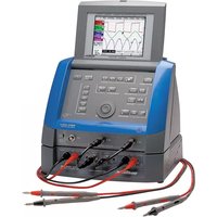
MTX 1032 - Measuring equipment METRIX - Free user manual and instructions
Find the device manual for free MTX 1032 METRIX in PDF.


User questions about MTX 1032 METRIX
0 question about this device. Answer the ones you know or ask your own.
Ask a new question about this device
Download the instructions for your Measuring equipment in PDF format for free! Find your manual MTX 1032 - METRIX and take your electronic device back in hand. On this page are published all the documents necessary for the use of your device. MTX 1032 by METRIX.
USER MANUAL MTX 1032 METRIX
natural_image
Two MTX 1032-8 micro devices with labeled ports and connectors (no visible text beyond branding)
Description MTX 1032-B
Vue indicative

text_image
Diagram of a printer with labeled parts, showing connections to ports and cablesLégende
Description MTX 1032-B (suite)
Description MTX 1032-C
Vue indicative
text_image
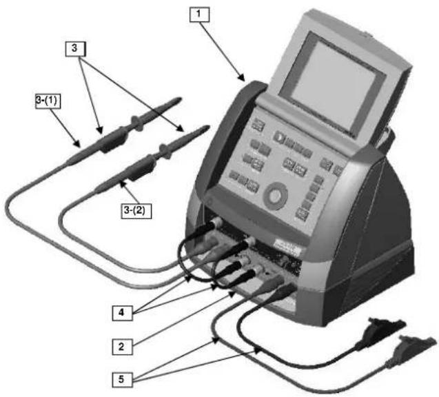
Diagram of an electronic testing device with labeled components including probes, coils, and a screen.Légende
Description MTX 1032-C (suite)
General Instructions
| Congratulations | You have just acquired anMTX 1032 differential probe.Congrataulations on your choice and thank you for your trust in the quality of our products. |
| Introduction | This differential probe is an important accessory for theMTX 3252andMTX 3352oscilloscopes.There are 2 models of theMTX 1032probes:MTX 1032-B:30 MHz model with female banana-socket inputsMTX 1032-C:50 MHz model with BNC inputsThis probe enables the differential input voltage to be attenuated and converted into low voltage available on the BNC output.The differential input is particularly useful for the measurement of semiconductor power circuits since no reference earth is required.It can be used for measurements on the following types of circuits:600 V CAT III in relation to the earth (MTX 1032-B)600 V CAT II in relation to the earth (MTX 1032-C) |
| Precautions | The protection provided by this probe may be compromised if wrongly used.The probe must only be used with a Class 1 oscilloscope connected to a protective earth.Do not open the instrument until you have disconnected the inputs and the mains lead. |
| Measurement categories | Overvoltage category IIis for equipment intended to be supplied from the building wiring. It applies both to plug-connected equipment and to permanently connected equipment.E.g.:Measurements on the network circuits of household appliances, portable tools and other similar appliances.Overvoltage category IIIis for equipment intended to form part of a building wiring installation. Such equipment includes socket outlets, fuse panels, and some mains installation control equipment.E.g.Measurements on distribution panels (including secondary meters), circuit breakers, cabling including cables, busbars, junction boxes, disconnecting switches, power outlets in the fixed installation, and industrial appliances and other equipment, such as motors permanently connected to the fixed installation |
| Warranty | This equipment is guaranteed for2 yearsagainst any defect in materials or workmanship, in accordance with the general terms and conditions of sale.During this period, the equipment can only be repaired by the manufacturer. The manufacturer reserves the right to carry out repair or replacement of all or part of the equipment.If the equipment is returned to the manufacturer, initial transport costs shall be borne by the customer. |
General instructions (continued)
Warranty (cont'd)
The warranty does not apply in the event of:
• unsuitable use of the equipment or use with other incompatible equipment
- modification of the equipment without the explicit authorization of the manufacturer's technical services
• repair carried out by a person not certified by the manufacturer
- adaptation for a specific application, not included in the definition of the equipment or the user's manual
- an impact, a fall or flooding.
Maintenance and metrology
Information and contact details : your nearest distributor.
Symbols used
Warning: Risk of danger. Refer to the operating manual.
Earth
Unpacking - Repacking

All the equipment was verified mechanically and electrically before shipping.
When you receive it, carry out a quick check to detect any damage that may have occurred during transport. If necessary, contact our sales department immediately and register any legal reservations with the carrier.
In the event of reshipping, it is preferable to use the original package. Indicate the reasons for the return as clearly as possible in a note attached to the equipment.
Fastening the probe to the oscilloscope
Assembly procedure
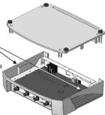
The fittings to fasten the probe to the MTX oscilloscope are located inside the probe unit.
- Turn the probe over.
- Unscrew the base.
- 4 screws and 4 spacers are located in one of the two housings inside the unit.
- Remove the 4 oscilloscope feet.
- Take the protective caps off the 4 corners of the probe and insert the spacers.
- Assemble the probe and oscilloscope with the fittings.
- Screw the base of the probe back on.
natural_image
3D technical illustration of an electronic device housing with internal components and mounting holes (no text or symbols)Cleaning

- Disconnect all the measurement leads.
- Turn the instrument off.
- Clean it with a damp cloth and soap.
- Never use abrasive products or solvents.
- Allow to dry before any further use.
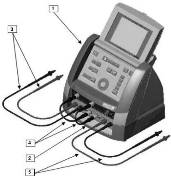
Description of MTX 1032-B
Illustration
text_image
Diagram of a printer with labeled parts including paper, print, and cable connectionsKey
- MTX oscilloscope
- MTX 1032-B probe unit (see detail of front panel, below)
- Set of 2 measurement leads (1 black, 1 red) with banana connectors
- Set of 2 short coaxial cables
- Set of 2 measurement leads (1 black, 1 red)
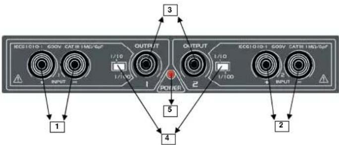
Front panel of MTX 1032-B probe
text_image
KE01010. G00V CATB I MG/GpF OUTPUT 1/10 1/100 POWER OUTPUT 1/10 1/100 2 3 4 2 INPUTKey
- Differential input "I" (banana sockets)
- Differential input "2" (banana sockets)
- Outputs 1 and 2 (BNC)
- Selection of attenuation coefficient: 1/10, 1/100
- ON/OFF LED
Description of MTX 1032-B (continued)
Description
The MTX 1032-B probe has 2 differential channels.
A LED indicates that it is switched on.
The probe does not include its own display facilities; it is designed for connection to the CH1 and CH2 inputs of the oscilloscope so that the differential signal present on the +/- inputs can be viewed.
Furthermore, this probe has two switches for selecting 1/10 or 1/100 as the attenuation coefficient.
For each differential channel, the front panel of the MTX 1032-B probe includes:
• 2 safety banana connectors for the +/- inputs
• 1 BNC for output to the oscilloscope
• 1 attenuation coefficient selection switch: 1/10, 1/100
This probe is a stand-alone unit powered by the 230 VAC 50 Hz / 60 Hz mains supply.
Functional description
- Power up the probe using the mains lead. Check that the corresponding LED comes on.
- Connect the probe's output "I" coaxial cable to input CH1 on the oscilloscope.
- Connect the probe's output "2" coaxial cable to input CH2 on the oscilloscope.
- Connect the red banana lead to the positive input of the probe and the black banana lead to the negative input of the probe.
- Remove the protective caps from the lead touch prods and input the signal to be measured.
- Select the appropriate attenuation coefficient for the signal to be measured (1/10 or 1/100) using the probe switch. The signal is then displayed on the oscilloscope screen.
- When the measurements are finished, disconnect the leads. Switch off the probe and then disconnect the oscilloscope.
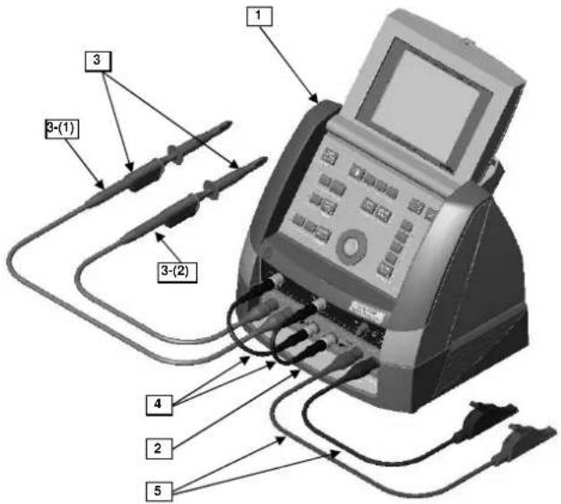
Description of MTX 1032-C (continued)
Illustration
text_image
Diagram of a medical or laboratory testing device with labeled components including test probes and connected cablesKey
- MTX oscilloscope
- MTX 1032-C probe unit (see detail of front panel, below)
- Set of two HX0003 (HX0004) 1/10 probes equipped with the HX0008 adapter
- Set of 2 short coaxial cables
- Set of 2 measurement leads (1 black, 1 red)
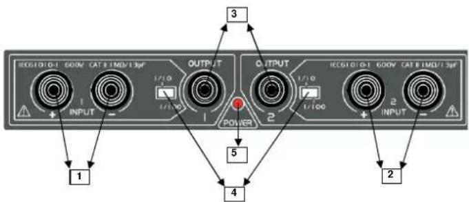
Front panel of MTX 1032-C probe
text_image
1 INPUT OUTPUT 3 1/10 1/100 POWER 2 1/10 1/100 OUTPUT 4 2 INPUTKey
- Differential input "I" (BNC)
- Differential input "2" (BNC)
- Outputs 1 and 2 (BNC)
- Selection of attenuation coefficient: 1/10, 1/100
- ON/OFF LED
Description of MTX 1032-C (continued)
Description
The MTX 1032-C probe has 2 differential channels.
A LED indicates that it is switched on.
The probe does not include its own display facilities; it is designed for connection to the CH1 and CH2 inputs of the oscilloscope so that the differential signal present on the +/- inputs can be viewed.
Furthermore, this probe has two switches for selecting 1/10 or 1/100 as the attenuation coefficient.
For each differential channel, the front panel of the MTX 1032-C probe includes:
• 2 BNC connectors for the +/- inputs
• 1 BNC for output to the oscilloscope
• 1 attenuation coefficient selection switch: 1/10, 1/100
The MTX 1032-C is a stand-alone unit powered by the 230 VAC 50 Hz / 60 Hz mains supply.
Functional description
- Power up the probe using the mains lead. Check that the corresponding LED comes on.
- Connect the probe's output "I" coaxial cable to input CH1 on the oscilloscope.
- Connect the probe's output "2" coaxial cable to input CH2 on the oscilloscope.
- Connect the red BNC lead to the positive input of the probe and the black BNC lead to the negative input of the probe.
- Capture the signal to be measured.
- Select the appropriate attenuation coefficient for the signal to be measured (1/10 or 1/100) using the probe switch. The signal is then displayed on the oscilloscope screen.
- When the measurements are finished, disconnect the leads. Switch off the probe and then disconnect the oscilloscope.
Compensation of 1/10 probes
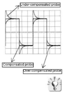
text_image
Under-compensated probe Compensated probe Over-compensated probe- Set the attenuation coefficient of the MTX 1032-C probe to 1/10.
- Connect the first 1/10 probe [ref. 3-(1)] to the positive input of the MTX 1032-C probe and then capture the Probe Adjust signal.
- Compensate the probe and then disconnect it from the Probe Adjust output.
- Connect the second 1/10 [ref. 3-(2)] to the negative input, capture the Probe Adjust signal and compensate the probe.
- Connect the two 1/10 probes simultaneously to the Probe Adjust output to check that the adjustment is balanced: the amplitude of the square signal is cancelled out.
To use the 1/10 probes of the MTX oscilloscope with the MTX 1032-C probe, remove the sprung hook and fit the crocodile clamp.
Technical characteristics
| Characteristics | MTX 1032-B MTX 1032-C | |
| Inputs Female banana sockets | BNC | |
| Mains power supply 300 V - CAT II | 230 VAC ± 10% 50/60 Hz | |
| Fuse 0.125 A - 230 V | ||
| Range of variation of:- mains voltage- mains frequency | 230 VAC ± 10 %50/60 Hz | |
| Consumption < 5 W | ||
| Measurement inputs 600 V - CAT | III 600 V - CAT II | |
| Differential input range 1/101/100 | ± 0.1 to 40 V± 1 to 400 V | |
| Bandwidth 30 MHz 50 MHz | ||
| Rise time 11.7 ns | 7 ns | |
| Impedance | 1 MΩ // 6 pF | 1 MΩ // 13 pF |
| Maximum voltage in common mode: 1/10 position1/100 position | ± 50 V± 600 V | |
| Common mode rejection | 80 dB at 50 Hz50 dB at 1MHz | |
| Switchable attenuationcoefficients | 1/101/100 | |
| Accuracy of the attenuationcoefficients (1 kHz signal) | ± 3 % | |
| OUT1 and OUT2 outputsMaximum DC levelOutput impedanceNoise levelResidual offset | 1 MΩ loaded output± 4 V50 Ω10 mVdc< 10 mV | |
| Operating temperature | 0 to 50°C | |
| Relative humidity | < 80 % up to 31°C | |
| Sealing | IP 40 | |
| Weight | 1.2 kg | |
| Dimensions | 270 x 250 x 63 mm | |
CE
EMC
This equipment has been designed to conform to current EMC standards and its compatibility has been tested as per Standard NF EN 61326-1 Influence quantity: 20mVcc in the presence of a 3V / m electromagnetic field
DBT
NF EN 61010-1 + NF EN 61010-2-030
Environmental conditions: altitude < 2000 m - pollution level 2 Indoor use
Supply
MTX 1032-B
• 1 elbowed mains lead
• 2 BNC-BNC leads 0.2 m long
• 2 sets of 4 mm touch-prod leads
MTX 1032-C
• 1 elbowed mains lead
• 2 BNC-BNC leads 0.2 m long
• 1 sets of BNC-Banana leads
• 2 crocodile clips for HX0003 (HX0004) probe
natural_image
3D diagram of an electronic device showing internal components and a housing (no text or symbols)Pflege

text_image
Diagram of a printer with labeled parts including ports and cables, showing connections to the printer's screen.Legende
text_image
Diagram of an electronic testing device with labeled components including probes, display screen, and wiring connectionsLegende
natural_image
3D mechanical assembly diagram showing internal components with no visible text or symbolsManutenzione

text_image
Diagram of a printer with labeled parts and connecting cables, showing connections to the printer's screen.Didascalia
text_image
Diagram of an electronic testing device with labeled components including probes and a display screenDidascalia
natural_image
3D diagram of an electronic device showing internal components and housing (no text or symbols)Limpieza