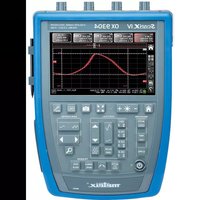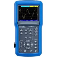
ScopiX IV OX9062 - Measuring equipment METRIX - Free user manual and instructions
Find the device manual for free ScopiX IV OX9062 METRIX in PDF.


User questions about ScopiX IV OX9062 METRIX
0 question about this device. Answer the ones you know or ask your own.
Ask a new question about this device
Download the instructions for your Measuring equipment in PDF format for free! Find your manual ScopiX IV OX9062 - METRIX and take your electronic device back in hand. On this page are published all the documents necessary for the use of your device. ScopiX IV OX9062 by METRIX.
USER MANUAL ScopiX IV OX9062 METRIX
4.7. Communication....53
11.3. IEEE 488.2 common commands ....110
- ANNEXES....115
natural_image
Blue and gray electronic device rear panel with four ports and a display screen (no visible text or symbols)text_image
Save to File Type Setup Traces Math. Comment --- File: scopix_2017-02-24_13-49-02text_image
Save to File Setup Type Comment --- File: scopix_2017-02-24_13-49-564.3 Mode LOGGER

Fri Sep 29 2017, 09:52:20
Bus quality: 100%
| Min value allowed | Max value allowed | Measurement | Error | |
| VHigh | 1.000 V | 3.600 V | 3.090 V | OK |
| VLow | -3.600 V | -1.000 V | -3.308 V | OK |
| Time Rise | 75.00 ns | 300.0 ns | 110.5 ns | OK |
| Time Fall | 75.00 ns | 300.0 ns | 102.8 ns | OK |
| TRise-TFall | --- | --- | 9.900 ns | --- |
| Time Data | --- | --- | 679.6 ns | --- |
| Jitter | --- | 24.0% | 0.3% | OK |
text_image
Date / Time 25 Apr 2017 10:40:37 Language American English Saver 15 minutes 30 minutes 1 hour No Automatic shutdown 30 minutes 1 hour 4 hours No Default setup Recall
Date / Heure
text_image
INSTRUMENTS NONAME V0.00/ZZ @ 14.3.250.51 NONAME V0.00/ZZ @ 14.3.250.48 NONAME V0.00/ZZ @ 14.3.250.65 OX7102-C V2.23/CC @ 14.3.212.33text_image
Save to File Type Setup Meas. Comment --- File: scopix_2017-02-28_10-19-22
IEC 61010-1 (2010 + amendement 1)

IEC 61000-2-030 (2017)
line
| Fréquence | Tension max. (VRMS) | | --------- | ------------------- | | 0.01 MHz | 600 Vrms | | 1 MHz | 600 Vrms | | 10 MHz | 600 Vrms | | 100 MHz | 100 Vrms | | >100 MHz | 5 Vrms |NRf (flexible Numeric Representation).
| ABORT | (Command)The ABOR command aborts the acquisition in progress.If the instrument is set in the single mode, the acquisition is stopped. The instrument stays in the starting status.If the instrument is in continuous mode, the acquisition in progress is stopped and the following starts.Note : if no acquisition is running, this command has no effect. |
| ARM[:SEQUence{[3]|4]}:COUPling | (Command/Query)The ARM:COUPcommand determines the coupling associated to the trigger auxiliary source.To the question ARM:COUP?, the instrument returns the coupling associated to the trigger auxiliary source. |
| ARM[:SEQUence{[3]|4]}:FILTER:HPASs[:STATE] | (Command/Query)The ARM:FILT:HPAS <1|0|ON|OFF> command validates or devalidates the reject of the low frequencies associated to the trigger auxiliary source.■ 1|ON: activates the reject of the low frequencies (LF Reject coupling)■ 0|OFF: deactivates the reject of the low frequencies; the coupling DC is then activated.To the question ARM:FILT:HPAS?, the instrument returns the activation status of the low frequencies reject associated to the trigger auxiliary source. |
| ARM[:SEQUence{[3]|4]}:FILTER:LPASs[:STATE] | (Command/Query)The ARM:FILT:LPAS <1|0|ON|OFF> command validates or devalidates the high frequencies reject associated to the trigger auxiliary source.■ 1|ON: activates the high frequencies reject (HF Reject coupling)■ 0|OFF: deactivates the high frequencies reject ; the DC coupling is then activated.To the question ARM:FILT:LPAS?, the instrument returns the activation status of the high frequencies reject associated to the trigger auxiliary source. |
| ARM[:SEQUence{[3]|4]}:HYSTeresis | (Command/Query)The ARM:HYSTcommand sets the amplitude of the hysteresis which rejects the noise associated to the trigger auxiliary source.is a value in format NR1 with following values :■ 0: no noise rejection, hysteresis is about 0.5 div.■ 3: activated noise rejection, hysteresis is about 3 div.To the question ARM:HYST?, the instrument returns the amplitude of the hysteresis used for the noise rejection associated to the trigger auxiliary source. |
| ARM[:SEQUence{[3]|4]}:LEVel | (Command/Query)The ARM:LEVcommand sets the trigger level of the auxiliary source.is a value in format, it may be followed or not by a multiple and by the unit. By default, the value is expressed in volt.To the question ARM:LEV?, the instrument returns the trigger level of the auxiliary source.Response format:expressed in volt.value in format |
| ARM[:SEQUence{[3]|4]}:SLOPe | (Command/Query)The ARM:SLOPcommand determines the trigger front of the auxiliary source.POSitive: rising frontNEGative: falling frontTo the question ARM:SLOP?, the instrument returns the polarity of the trigger front of the auxiliary source. |
| ARM[:SEQUence{[3]|4}]:SOURce | (Command/Query)The ARM:SOURcommand determines the auxiliary trigger source of the instrument.INTernal{1|2|3|4} corresponds to the trigger source (1, 2, 3, 4 channels) of the instrument on SCOPIX and SCOPIX BUS.To the question ARM:SOUR?, the instrument returns the used trigger auxiliary source. |
| AUTOSet:EXEcute | (Command)The AUTOS:EXE command starts an autoset on each active channel. |
| CALCulate:MATH{[1] |2|3|4}[:EXPReession][:DEFine] | (Command/Query)The CALC:MATH{[1]|2|3|4}<(function)> command defines and activates the mathematical function of the selected signal.is the definition of the mathematical function.(ch1-ch2) subtracts the channel 1 from channel 2.To the question CALC:MATH{[1]|2|3|4}?, the instrument returns the mathematical function of the selected signal. |
| CALCulate:MATH{[1] |2|3|4}[:EXPReession]:DELe | (Command)The CALC:MATH{[1]|2|3|4}:DEL command deletes the mathematical function of the selected signal. |
| CALCulate:TRANSform:FREQuency[:STATE] | (Command/Query)The CALC:TRAN:FREQ <1|0|ON|OFF> command activates the FFT calculation.To the question CALC:TRAN:FREQ?, the instrument returns the activation status of the FFT calculation. |
| CALCulate:TRANSform:FREQuency:WINDow | (Command/Query)CALC:TRAN:FREQ:WINDwindow used for the FFT calculation.To the question CALC:TRAN:FREQ:WIND?, the instrument returns the type of window used for the FFT calculation. |
| DEVice:MODE | (Command/Query)The DEV:MODcommand selects the principal mode of the instrument.To the question DEV:MOD?, the instrument returns the mode in which it has been configured. |
| DISPLAY: BRIGHTness | (Command/Query)The DISP:BRIGcommand sets the backlight intensity of the screen.is a value in formatwithout unit, in the range [0.0 1.0]To the question DISP:BRIG?, the instrument returns the backlight level of the screen. |
| DISPLAY[:WINDow]:CURSor:REFerence | (Command/Query)The DISP:CURS:REFcommand selects the reference for the automatic and manual measurements.To the question DISP:CURS:REF?, the instrument returns the signal used as reference. |
| DISPLAY[:WINDOW]:CURSor:STATE | (Command/Query)The DISP:CURS:STAT <1|0|ON|OFF> command activates or inhibits the manual measurements.■ 1|ON: activates the manual measurements■ 0|OFF: inhibits the manual measurementsTo the question DISP:CURS:STAT?, the instrument returns the activation status of the manual measurements. |
| DISPLAY[:WINDOW]:CURSor:TIME{[1]|2|3}:POSITION | (Command/Query)The DISP:CURS:TIME{[1]|2|3}:POScommand sets the position of the selected TIMEx manual cursor.is a value in format NRf, it may be followed or not by a multiple and the unit. By default the value is expressed in second.This command acts on the manual cursors represented on the screen by the X-symbol accompanied by an index (1, 2 or φ).To the question DISP:CURS:TIME{[1]|2|3}:POS?, the instrument returns the horizontal position of the selected manual cursor.Response format:expressed in second. |
| DISPLAY[:WINDOW]:CURSor:TIME{[1]|2|3}:YPOSITION? | (Command/Query)To the question DISP:CURS:TIME{[1]|2|3}:YPOS?, the instrument returns the value of the sample of the reference channel, at the position defined by the TIMEx manual cursor.Response format :expressed in second. |
| DISPLAY[:WINDOW]:CURSor:VOLT{[1]|2}:POSITION | (Query)To the question DISP:CURS:VOLT{[1]|2}:POS?, the instrument returns the position of the selected VOLTx manual cursor.This command acts on the manual cursors represented on the screen by the X-symbol accompanied by an index (1, 2).Response format :expressed in volt. |
| DISPLAY[:WINDOW]:TRACe:FORMAT | (Command/Query)The DISP:TRAC:FORMcommand selects the display mode of the instrument.■ A validates the Oscilloscope display mode : Y = f(t)■ XY validates the XY display mode : Y = f(x)To the question DISP:TRAC:FORM?, the instrument returns the active display mode. |
| DISPLAY[:WINDOW]:TRACe:MODE | (Command/Query)The DISP:TRAC:MODEcommand selects the display mode.■ NORMAL validates the Vector display mode.■ ENVelope validates the Envelope display mode.To the question DISP:TRAC:MODE?, the instrument returns the active display mode. |
| DISPLAY[:WINDOW]:TRACe:STATE{[1]|2|3|4} | (Command/Query)The DISP:TRAC:STAT{[1]|2|3|4} <1|0|ON|OFF> command validates or devalidates the selected signal.To the question DISP:TRAC:STAT{[1]|2|3|4}? , the instrument returns the validation status of the selected signal. |
| DISPLAY[:WINDOW]:TRACe:X[:SCALe]:PDIVision | (Command/Query)The DISP:TRAC:X:PDIVcommand sets the value of the time base.is a value in format, it may be followed or not by a multiple and by the unit. By default, the value is expressed in second.Example: to get a time base of 1 μs, following values can be entered: 1E-3ms or 1E-6 or 0.000001s or 0.000001 or else 1us.To the question DISP:TRAC:X:PDIV?, the instrument returns the value of the time base. Response format :<measured value><NL>value in format <NR3> expressed in second. |
| DISPLAY[:WINDOW]:TRACe:XY:XDEFine | (Command/Query)The DISP:TRAC:XY:XDEFcommand selects the signal positioned on the X-basis.To the question DISP:TRAC:XY:XDEF?, the instrument returns the signal used on the X-basis. |
| DISPLAY[:WINDOW]:TRACe:XY:YDEFine | (Command/Query)The DISP:TRAC:XY:YDEFcommand selects the signal positioned on the Y-basis.To the question DISP:TRAC:XY:YDEF?, the instrument returns the signal used on the Y-basis. |
| DISPLAY[:WINDOW]:TRACe:Y:LABel{[1]|2|3|4} | (Command/Query)The DISP:TRAC:Y:LAB{[1]|2|3|4} < "label"> command determines the unit of the selected signal.The unit is selected among the upper-case letters of the alphabet (A to Z), and is composed of a name up to 3 letters.To the question DISP:TRAC:Y:LAB{[1]|2|3|4}?, the instrument returns the unit of the selected signal. |
| DISPLAY[:WINDOW]:TRACe:Y[:SCALe]:PDIVision{[1]|2|3|4} | (Command/Query)The command DISP:TRAC:Y:PDIV{[1]|2|3|4}<scale|MAX|MIN> command sets the value of the probe coefficient for the selected signal.is a value at NRf format.To the question DISP:TRAC:Y:PDIV{[1]|2|3|4}?, the instrument returns the value of the probe coefficient for the selected signal. |
| DISPLAY[:WINDOW]:TRACe:Y:SPACING | (Command/Query)The DISP:TRAC:Y:SPACcommand specifies the type of scale applied to the Y-axis.To the question DISP:TRAC:Y:SPAC?, the instrument returns the type of scale applied to the Y-axis. |
| FORMAT[:DATA] | (Command/Query)The FORMcommand selects the data format of the trace transfer.INTeger: The data transmitted consists in whole numbers, unsigned with a length of 32 bits, preceded by the heading #an. n represents the number of data items to transmit.a gives the number of figures making up n.# The transmission for 4 data items (74, 70, 71, 76) is #14JFGLASCII: The data is transferred using ASCII characters according to <NR1> numbering from 0 to 255. Each number is separated by a comma.# The transmission for 4 data items (74, 70, 71, 76) is 74,70,71,76HEXadecimal: The data is transferred using ASCII characters according to a numbering in base 16 on 8 bits. Each number is preceded by #H and separated by a comma.# The transmission for 4 data items (74, 70, 71, 76) is #H4A,#H46,#H47,#H4CBINary: The data is transferred using ASCII characters according to a numbering in base 2 on 8 bits. Each number is preceded by #B and separated by a comma.# The transmission for 4 data items (74, 70, 71, 76) is #B1001010,#B1000110,#B1000111,# B1001100To the question FORM?, the device returns the format selected for the trace transfer. |
FORMAT:DINTerchange (Command/Query)
The FORM:DINT <1|0|ON|OFF> command activates or inhibits the trace transfer in DIF format.
■ ON|1 activates the trace transfer in DIF format.
■ OFF|0 the trace transfer data is raw.
To the question FORM:DINT?, the device returns the activation status of the DIF format.
Response format: DIF format:
(DIF (VERsion
DIMension=X (TYPE IMPLICIT
SCALe
SIZE
U N ITs "S")
DIMension=Y (TYPE EXPLICIT
SCALe
OFFSET 393216
U N ITs "V")
DATA(CURVe ()))
: 1999.1 means that SCPI version 1999 is used. This is the first software version of the remote control management programme.
It represents the time difference between two samples.
It represents the number of samples to be transferred. It can vary from 1 to 100 000.
It represents the difference in volt between two consecutive values of the analogue digital converter.
is a block containing the samples. This data comprises only the values resulting from the analogue digital converter. This block is in the format specified by the FORMAT[:DATA] command.
HCOPy:SDUMp[:IMMediate] (Command)
The HCOP:SDUM [file.png] command starts a hard copy. The parameter file.png is optional. If this parameter is not present, a default filename is created from current date and time.
The file is created in the "screenshots" directory of the active device (SDCARD or internal memory).
HELP[?] (Query)
To the question HELP? [« directory entry »] the instrument answers helping in the SCPI commands available.
« directory entry » is a key word (short or long form) of first level in the tree of the command. No distinction is made between small and capital letters.
In absence of parameter, the list of the key words accepted by the function is given. When a key word is introduced, the list and the syntax of all the commands starting with this word is returned by the function.
INITiate:CONTINUOUS:NAME (Command)
INIT:CONT:NAME
In the CAPTure mode, the capture of faults in (Recorder) files is used.
INITiate[:IMMediate]:NAME (Command)
INIT:NAME
INPut{[1]|2|3|4}:COUPling (Command/Query)
The INP{[1]|2|3|4}:COUP
To the question INP{[1]|2|3|4}:COUP?, the instrument returns the coupling of the selected channel.
| INPUT:DMM:BANDwidth:RESolution | (Commande/Query)The INP{[1]|2|3|4}:DMM:BAND:REScommand limits the channel bandwidth to a value among : 625 Hz, 5 kHz, 0 (no limit), directly higher or equal to the required value.To the question INP{[1]|2|3|4}:DMM:BAND:RES? the instrument shows the cutoff frequency of the low-pass filter in use (625 Hz, 5 kHz or 0). |
| INPUT{[1]|2|3|4}:DMM:COUpling | (Command/Query)The INP{[1]|2|3|4}:DMM:COUPcommand affects the coupling of the selected channel.To the question INP{[1]|2|3|4}:DMM:COUP? the instrument returns the current coupling of the selected channel. |
| MEASure:AC? | (Query)To the question MEAS:AC?,the instrument returns the RMS voltage over an integer number of periods (CYCle) or over the measurement interval (INTerval).Response format:expressed in volt. |
| MEASure:AMPLitude? | (Query)To the question MEAS:AMPLitude?the instrument returns the amplitude of the selected signal. |
| MEASure:CURSor:DTIME? | (Query)To the question MEAS:CURS:DTIME?, the instrument returns the time delay between cursors 1 and 2.Response format:value in formatexpressed in second. |
| MEASure:CURSor:DVOLT? | (Query)To the question MEAS:CURS:DVOLT?, the instrument returns the difference between cursors 1 and 2.Response format:value in formatexpressed in volt. |
| MEASure:DMM? | (Query)To the question MEAS:DMM?the instrument returns the value of the main measurement for the selected channel.INT1 to INT4 index are associated with channels 1 to 4. Use the index to find INT5 power measurement.Before using the command MEAS: DMM? INT5, the instrument must be configured to measure the power measurement (see [SENSe]: Function).Response format:value format |
| MEASure:FALL:OVERshoot? | (Query)To the question MEAS:FALL:OVER?the instrument returns the negative overshoot of the selected signal.Response format:value in formatexpressed in percent. |
| MEASure:FALL:TIME? or MEASure:FTIME? | (Query)To the question MEAS:FALL:TIME?the instrument returns the fall time of the selected signal.Response format:value in formatexpressed in second. |
| MEASure:FREQuency? | (Query)To the question MEAS:FREQ?the instrument returns the frequency of the selected signal.Response format:value in formatexpressed in hertz. |
| MEASure:HIGH? | (Query)To the question MEAS:HIGH?the instrument returns the value of the high level level of the selected signal.Response format:value in formatexpressed in volt. |
| MEASure:LOW? | (Query)To the question MEAS:LOW?the instrument returns the low level value of the selected signal.Response format:value in formatexpressed in volt. |
| MEASure:MAXimum? | (Query)To the question MEAS:MAX?the instrument returns the maximum value of the selected signal.Response format:value in formatexpressed in volt. |
| MEASure:MINimum? | (Query)To the question MEAS:MIN?the instrument returns the value minimum of the selected signal.Response format:value in formatexpressed in volt. |
| MEASure:NWIDth? | (Query)To the question MEAS:NWID?the instrument returns the negative pulse width of the selected signal.Response format:value in formatexpressed in second. |
| MEASure:PDUTycycle? | (Query)To the question MEAS:PDUT?the instrument returns the duty cycle of the selected signal.Response format:value in formatexpressed in percent. |
| MEASure:PERiod? | (Query)To the question MEAS:PERiod?the instrument returns the period of the selected signal.Response format:value in formatexpressed in second. |
| MEASure:PHASE? | (Query)To the question MEASPHAS?, the instrument returns the phase of φ-cursor in relation to cursors 1 and 2. The difference between the cursor 1 and 2 represents 360°. The cursor 1 equal to 0° and the cursor 2, 360°.Response format:value in formatexpressed in degree. |
| MEASure:PTPeak? | (Query)To the question MEAS:PTP?the instrument returns the peak-to-peak value of the selected signal.Response format:value in formatexpressed in volt. |
| MEASure:PULse:COUNT? | (Query)To the question MEAS:PUL:COUN?the instrument returns the pulse count on screen of the selected signal.Response format:value in format. |
| MEASure:PWIDth? | (Query)To the question MEAS:PWID?the instrument returns the positive pulse width of the selected signal.Response format:value in formatexpressed in second. |
| MEASure:RISE:OVERshoot? | (Query)To the question MEAS:RISE:OVER?the instrument returns the positive overshoot of the selected signal.Response format:value in formatexpressed in percent. |
| MEASure:RISE:TIME?or MEASure:RTIME? | (Query)To the question MEAS:RISE:TIME?the instrument returns the rise time of the selected signal.Response format:value in formatexpressed in second. |
| MEASure:SUM? | (Query)To the question MEAS:SUM?the instrument returns the integral measurement of the selected signal.Response format:value in format. |
| MEASure:VOLT[:DC]? | (Query)To the question MEAS:VOLT?the instrument returns the average value of the selected signal.Response format:value in formatexpressed in volt. |
| MMEMory:CATalog? | (Query)To the question MMEM:CAT?[]the device returns the list of files present in the local memory.If the file system is not specified, the default file system is used (see command MMEM:MSIS).Response format:, 0,is in NR1 format.= ""file",0< "file">consists in a name of 20 letters maximum, followed by a period and the 3-letter extension.is▪ STAT for the extension files .cfg▪ TRAC for the extension files .trc and .rec▪ ASC for the extension files .txt and .fct▪ MAC for the extension files .mac▪ BIN for all other files |
| MMEMory:CDIR? | (Command/Query)TheMMEM:CDIR<"directory">command determines the working directory on the default device.To the questionMMEM:CDIR?the instrument returns the working directory. |
| MMEMory:DATA | (Command/Query)TheMMEM:DATA<"file>",command transfers a file from the PC to the device.<"file">consists in a name of 20 letters maximum, followed by a period and the 3-letter extension. If the file already exists, it will be overwritten by the new file.is all of the data in the file preceded by the heading #an, n being the data number and a, a figure indicating the number of figures making up n.To the questionMMEM:DATA?<"file>", the device transfers the file named to the PC.Response format: |
| MMEMory:DELete | (Command)TheMMEM:DEL<"file">[,command deletes a file.If the file system is not specified, the default file system is used (see command MMEM:MSIS and MMEM:CDIR). |
| MMEMory:LOAD:MACRo | (Command)TheMMEM:STOR:MACR <|file'>,command reads a mathematical function from a ".fct" file and assigns it to the indicated signal.If the file system is not specified, the default file system is used (seeMMEM:MSISandMMEM:CDIR).<"file">consists in a name of 20 letters maximum, followed by a period and the FCT extension. |
| MMEMory:LOAD:STATe | (Command)TheMMEM:LOAD:STAT<"file">[,command reads an instrument configuration from a ".cfg" file.If the file system is not specified, the default file system is used (see commandMMEM:MSISandMMEM:CDIR).<"file">consists in a name of 20 letters max., followed by a period and the CFG extension. |
| MMEMory:LOAD:TRACe | (Command)MMEM:LOAD:TRAC<TRACE>,<file.trc">[,command reads traces defined in a ".trc" file.If the file system is not specified, the default file system is used (see commandMMEM:MSISandMMEM:CDIR).<"file">consists in a name of 20 letters maximum, followed by a period and the TRC extension. |
| MMEMory:MSIS | (Command/Query)TheMMEM:MSIS<LOCAL|SDCARD>]is used to select the default mass storage support.To the question MMEM:MSIS? The instrument returns the default mass storage support. |
| MMEMory:STORE:MACRo | (Command)TheMMEM:STOR:MACR <|file'>,command generates a file ".fct" from the specified mathematical function in the chosen file system.If the file system is not specified, the default file system is used (seeMMEM:MSISandMMEM:CDIRcommand).<"file">consists in a name of 20 letters maximum, followed by a period and the fct extension. |
| MMEMory:STORE:STATe | (Command)TheMMEM:STOR:STAT<"file">[,command generates a ".cfg" file from the instrument configuration, in the selected file system.If the file system is not specified, the default file system is used (see commandMMEM:MSISandMMEM:CDIR).<"file">consists in a name of 20 letters maximum, followed by a period and the CFG extension. |
MMEMory:STORe:TRACe (Command)
The MEMEM:STOR:TRAC <"file.trc">[,
If the file system is not specified, the default file system is used (see commands MMEM:MSIS and MMEM:CDIR).
<"file"> consists in a name of 20 letters maximum, followed by a period and the TRC extension.
PASSFAIL:BEEP (Command/Query)
The PASSFAIL:BEEP <1|0|ON|OFF> command controls the instrument beeper when the condition defined with the PASSFAIL:DISPLAY command is effective.
To the question PASSFAIL:BEEP?, the instrument returns the state of the beeper.
PASSFAIL:CONTROL (Command/Query)
The PASSFAIL:CONT <1|0|ON|OFF> command is used to start/stop the passfail functionality in respect with the different tunings defined with the other PASSFAIL commands.
To the question PASSFAIL:CONT?, the instrument returns "1" ou "0"
PASSFAIL:COUNT:ALL? (Query)
To the question PASSFAIL:COUNT:ALL?, the instrument returns the total number of acquisitions obtained since last passfail start operation.
PASSFAIL:COUNT:FAIL? (Query)
To the question PASSFAIL:COUNT:FAIL?, the instrument returns the number of acquisitions outside the limits defined by the mask, obtained since last passfail start operation.
PASSFAIL:COUNT:PASS? (Query)
To the question PASSFAIL:COUNT:PASS?, the instrument returns the number of acquisitions inside the limits defined by the mask, obtained since last passfail start operation.
PASSFAIL:DISPLAY[?] (Command/Query)
The PASSFAIL:DISP
To the question PASSFAIL:DISP?, the instrument returns ALL, PASS or FAIL.
PASSFAIL:LOAD (Command)
The PASSFAIL:LOAD "
PASSFAIL:SAVE (Command)
The PASSFAIL:SAVE "
PASSFAIL:SOURCE (Command/Query)
The PASSFAIL:SOURCE
In a first step, this source can be used to compute a mask.
In a second step, this source is compared to the mask.
To the question PASSFAIL:SOURCE?, the instruments returns the string INTx where x represent the channel concerned.
PASSFAIL:STATE (Command/Query)
The PASSFAIL:STATE <1|0|ON|OFF> control the state of the PASSFAIL utility.
To the question PASSFAIL:STATE? The instrument replies "1" or "0".
PASSFAIL:XMASK (Command/Query)
The PASSFAIL:XMASK
PASSFAIL:YMASK (Command/Query)
The PASSFAIL:YMASK
[SENSe:]AVERAGE (Command/Query)
Use AVER:COUN
[SENSe:]AVERage (Command/Query)
Use AVER:TYPE
•
-
To the question AVER:TYPE?, the instrument returns the state of the min/max representation.
[SENSe:] AVERAGE (Command/Query)
[:STATE][?]
Use AVER:STATE <1|0|ON|OFF> command to set the REPETITIVE SIGNAL option.
If this option is set:
• Signals are build using several acquisitions
• Average filter is activated
To the question AVER:STATE?, the instrument returns the state of the REPETITIVE SIGNAL option.
[SENSe:]AVERAGE: (Command/Query)
BANDwidth{[1]|2|3|4}
[:RESolution][?]
Use AVER:BAND{[1]|2|3|4}
To the question AVER:BAND?, the instrument returns the value of the low pass filter cut frequency.
[SENSe:]FUNCTION[1][?] (Command/Query)
In the Multimeter and Logger mode, the FUNC
To the question AVER:BAND?, the instrument returns the channel 1 measurement type.
[SENSe:].RANGE{[1]|2|3|4} (Command/Query)
:AUTO[?]
In the Multimeter mode, the RANGE{[1]|2|3|4}:AUTO <0|1|ON|OFF> is used to activate vertical AUTORANGING on the selected channel.
To the question RANGE{[1]|2|3|4}:AUTO?, The instrument returns AUTORANGING activity.
[SENSe:]RANGE[1] (Command/Query)
:CAPA[?]
In the Multimeter mode, the RANGE[1]:CAPA
To the question RANGe[1]:CAPA?, The instrument returns the capacimeter measurement range (NR3 format).
| [SENSe:]RANGE[1] :OHM[?] | (Command/Query)In the Multimeter mode, the RANGE[1]:OHMis used to set the measurement range of the capacimeter.is a value coded with the NRf format, and can be followed (or not) of the measurement unit.To the question RANGE[1]: OHM?, The instrument returns the ohmmeter measurement range (NR3 format). |
| [SENSe]:RANGE{[1]|2|3|4}:VOLT[?] | (Command/Query)In the Multimeter mode, the RANGE{[1]|2|3|4}:VOLTis used to set the measurement range of the voltmeter on the selected channel.is a value coded with the NRf format, and can be followed (or not) of the measurement unit.To the question RANGE{[1]|2|3|4}: VOLT?, the instrument returns the voltmeter measurement range (NR3 format). |
| [SENSe:]SWEep:OFFSET :TIME[?] | (Command/Query)Use SWE:OFFS:TIMEcommand to control horizontal position of a trace (run-after-delay or postrig).is a signed value coded with the NRf format, and can be followed (or not) of the measurement unit (s).To te question SWE:OFFS:TIME?, the instrument return the value of the horizontal position (NR3 format). |
| [SENSe]:VOLTage {[1]|2|3|4]:DC}:RANGE:OFFSET | (Command/Query)The VOLT{[1]|2|3|4}:RANG:OFFScommand sets the vertical offset of the time representation of the selected signal.is a value in NRf format, it may be followed or not by a multiple and the unit.By default the value is expressed in volt.To the question V{[1]|2|3|4}:RANG:OFFS?, the instrument returns the vertical offset of the selected signal.Response format:expressed in volt. |
| [SENSe]:VOLTage {[1]|2|3|4]:DC}:RANGE :PTPeak | (Command)The VOLT{[1]|2|3|4}:RANG:PTPcommand sets the full screen vertical sensitivity of the selected channel.is a value in NRf format, it may be followed or not by a multiple and the unit.By default the value is expressed in volt.To the question VOLT{[1]|2|3|4}:RANG:PTP?, the instrument returns the full screen vertical sensitivity of the selected channel.Response format:expressed in volt.If 10mV/div is the sensitivity displayed in the channel parameters, then theparameter = 8 x 10 mV/div. |
| SYSTem:COMMunicate :SOCKET:{[1]|2]}:ADDRess | (Command/Query)The SYST:COMM:SOCK:{[1]|2}::ADDR "" command defines the IP address of the instrument.Use index 1 to set ETHERNET and index 2 to set WIFI.is a chain of characters as: ip1.ip2.ip3.ip4, each of the ipX values must be included between 0 & 255.To the question SYST:COMM:SOCK:ADDR? the instrument returns the value of the current IP address.Response format: |
| SYSTem:COMMunicate :SOCKET:{[2]}:WIFI | (Command)SYST:COMM:SOCK < "ssid",,,"password">is used to set WIFI : the 3 parameters necessary to connect to the WIFI network. |
SYSTem:DATE (Command/Query)
The SYST:DATE
The possible values are:
0 to 9999 for the year range (1st range).
1 to 12 for the month range (2nd range).
1 to 31 for the day range (3rd range).
To the question SYST:DATE?, the instrument returns the date.
Response format:
with Y = year, M = month, D = day.
To the question SYST:ERR?, the instrument returns the number of error positioned at the top of the queue. The queue has a stack of 20 numbers and is managed as follows :
first in, first out.
As the SYST:ERR? questions arrive, the instrument returns the number of errors in order of arrival, until the queue is empty. Every more SYST:ERR? question involves a negative answer: character "0" (ASCII 48code). If the queue is full, the case at the top of the queue takes the value -350 (saturated queue).
The queue is empty:
- when the instrument is getting started.
- at the receipt of a *CLS.
- at the reading of the last error.
Response format:
with error = negative or 0, no error.
* Command error: They indicate that a syntax error has been detected by the syntax analyzer and causes event (-199 to -100) register bit 5, called CME, CoMmand Error to be set to 1.
-101 : Invalid character
-103 : Invalid separator
-104 : Data type error
-108 : Parameter not allowed
-109 : Missing parameter
-111 : Header separator error
-112: Program mnemonic too long
-113 : Undefined header
-114: Header suffix out of range
-121: Invalid character in number
-128 : Numeric data not allowed
-131 : Invalid suffix
-138 : Suffix not allowed
-141 : Invalid character data
-148: Character data not allowed
-151 : Invalid string data
-154 : String data too long
-171 : Invalid expression
* Execution errors: They indicate that an error has been detected at the moment of command execution and (-299 to -200) causes event register bit 4, called EXE, Execution Error, to be set to 1.
-200 : Execution error
-213 : Init ignored
-221: Sandtings conflict
-222 : Data out of range
-232 : Invalid format
-256 : File name not found
-257 : File name error
* Specific instrument errors: They indicate that an abnormal error has been detected during execution of a task, and causes (-399 to -300) event register bit 3, called DDE, Device Dependent Error to be set to 1.
-300: Device-specific error
-321 : Out of memory
-350 : Queue overflow
-360: Communication error
* Query errors: They indicate that an abnormal error has been detected during execution of a task, and cause (-499 to -400) event register bit 2, called QYE, QuerY Error, to be set to 1.
-400 : Query error
SYSTem:KLOCK (Command/Query)
The SYST:KLOCK <0|1|ON|OFF> command locks the front face.
To the question SYST:KLOCK?, the instrument returns the lock status of the front face.
SYSTem:SET (Command/Query)
The SYST:SET
To the question SYST:SET?, the device transfers the current configuration to the computer.
Response format:
SYSTem:TIME (Command/Query)
The SYST:TIME
The possible values are:
0 to 23 for the hour range (1st range).
0 to 59 for the minute range (2nd range).
0 to 59 for the second range (3rd range).
To the question SYST:TIME?, the instrument returns the hour.
Response format:
TRACe:CATalog (Query)
To the question TRAC:CAT?, the device returns the list of active signals.
# TRAC:CAT?
reply
reply INT1
reply INT1,INT3
TRACe[:DATA] (Query)
To the question TRAC?
Response format:
It contains the value of the 2500 samples encoded on 4 bytes, as follows (bit 31 = MSB):
| 31 24 | 19 | 0 | |
| Validity | - | samples coded on 20 bits | |
The validity byte contains 3 data bits:
| 31 | 30 | 29 | 28 | 27 | 26 | 25 | 24 |
| I | O | E | - | - | - | - | - |
with :
I: Invalidity, the sample is invalid if equal to 1
A: Age, used in slow mode, this sample is validated
E: Extrapolated, the sample is the result of an extrapolation if equal to 1.
| TRACe:LIMit (Command/Query) | |
| The TRAC:LIMcommand sets the left and right limits and the step of the data to be transferred. | |
| are parameters using format NR1. | |
| Their default value is 0, 2499 and 1. | |
| To the question TRAC:LIM?, the device returns the left and right limits and the step of the data to be transferred. | |
| TRIGger[:SEQUence{[1]|2|3|4]} :ATRIGger[:STATE] | (Command/Query) |
| The TRIG:ATRIG <1|0|ON|OFF> command validates or devalidates the automatic trigger mode. | |
| ■ ON|1 activates the automatic trigger mode. | |
| ■ OFF|0 activates the trigger mode. | |
| To the question TRIG:ATRIG?, the instrument returns the activation status of the automatic trigger mode. | |
| TRIGger[:SEQUence{[1]|2|3|4]}:COUPling | (Command/Query) |
| The TRIG:COUPcommand determines the coupling associated to the main trigger source. | |
| To the question TRIG:COUP?, the instrument returns the coupling associated to the main trigger source. | |
| TRIGger[:SEQUence{[1]|2|3|4]}:DEFine? | (Command/Query) |
| Returns the description of the indicated sequence : | |
| SEQUence1: EDGE | |
| SEQUence2: PULse | |
| SEQUence3: DELay | |
| SEQUence4: EVENt | |
| TRIGger:SEQUence{2|3}:DELay | (Command/Query) |
| The TRIG:SEQ{2|3}:DELcommand | |
| ■ in sequence 2 (Pulse) sets T1, the pulse time in following cases : « t > T1 », « t > T1 and t < T2 », « t < T1 or t > T2 » | |
| ■ in sequence 3 (trig-after-delay): sets the trigger delay on main sourceis a value in format, it may be followed or not by a multiple and by the unit. By default the value is expressed in second. | |
| To the question TRIG:SEQ{2|3}:DEL?, the instrument returns the trigger delay of the main source or the T1 pulse time according to the selected sequence. | |
| Response format: | |
| value in formatexpressed in second. | |
| TRIGger[:SEQUence2]:DELDpulse | (Command/Query) |
| The TRIG: DELDis used to set T2 in the following cases : « t > T1 and t < T2 », « t < T1 or t > T2 » | |
| TRIGger[:SEQUence[4]] :ECOunt | (Command/Query) |
| The TRIG:ECOcommand sets the number of events used in the trigger mode delayed by count. | |
| is a value in format NR1 from 3 to 16384. | |
| To the question TRIG:ECO?, the instrument returns the number of events to be counted before the trigger. | |
| TRIGger[:SEQUence{[1]|2|3|4]}:FILTER:HPASs[:STATE] | (Command/Query)The TRIG:FILT:HPAS <1|0|ON|OFF> command validates or devalidates the reject of the low frequencies associated to the main trigger source.■ 1|ON: activates the reject of the low frequencies (LF Reject coupling)■ 0|OFF: deactivates the reject of the low frequencies; the DC coupling is then activated.To the question TRIG:FILT:HPAS?, the instrument returns the activation status of the low frequencies reject associated to the trigger source. |
| TRIGger[:SEQUence{[1]|2|3|4]}:FILTER:LPASs[:STATE] | (Command/Query)To the question TRIG:FILT:LPAS?, the instrument returns the activation status the reject of the high frequencies associated to the trigger source.■ 1|ON: activates the high frequencies reject (HF Reject coupling)■ 0|OFF: deactivates the high frequencies reject; the DC coupling is then activated.To the question TRIG:FILT:LPAS?, the instrument returns the activation status the reject of the high frequencies associated to the trigger source. |
| TRIGger[:SEQUence{[1]|2|3|4]}:HYSTEResis[:STATE] | (Command/Query)The TRIG:HYSTcommand sets the amplitude of the hysteresis which rejects the noise associated to the trigger main source.is a value at NR1 format taking following values :■ 0: no noise reject, hysteresis is about 0.5 div.■ 3: activated noise reject, hysteresis is about 3 div.To the question TRIG:HYST?, the instrument returns the amplitude of the hysteresis which rejects the noise associated to the trigger main source. |
| IGger[:SEQUence[1]|3|4]:HOLDoff | (Command/Query)The TRIG:HOLDcommand sets the inhibition time of the trigger(Holdoff).is a value in format, it may be followed or not by a multiple and by the unit.By default the value is expressed in second.To the question TRIG:HOLD?, the instrument returns the trigger Holdoff time.Response format:expressed in second.value in format |
| TRIGger[:SEQUence{[1]|2|3|4]}:LEVel | (Command/Query)Used in the Seq. 1 to 4, the TRIG:LEVcommand sets the trigger level of the main source.is a value in format NRf, it may be followed or not by a multiple and by the unit.By default, the value is expressed in volt.To the question TRIG:LEV?, the instrument returns the trigger level of the main source in SEQuence1.Response format:expressed in volt. |
| TRIGger[:SEQUence{[1]|2|3|4]}:RUN:STATE | (Command/Query)The TRIG:RUN:STAT <1|0|ON|OFF> command starts or stops the acquisition.■ ON|1 acquisition starts.■ OFF|0 acquisition is stopped.To the question TRIG:RUN:STAT?, the instrument returns the trigger status. |
TRIGger[:SEQUence (Command/Query)
{[1]|2|3|4}]:SLOPe
TRIG:SEQ{[1]|2|3|4}:SLOP
in SEQuence2 : determines the polarity of the pulse
→ POSitive: positive pulse

→ NEGative: negative pulse
To the question TRIG:SEQ{[1]|2|3|4<}:SLOP?, the instrument returns the polarity trigger front or pulse according to the selected SEQuence.
In the other sequences: used to measure the triggering edge of the main source:
→ POSitive: rising front
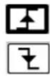
→ NEGative: falling front
TRIGger[:SEQUence (Command/Query)
{[1]|2|3|4}]:SOURce
The TRIG:SOUR
INTernal{1|2|3|4} corresponds to the trigger source (1, 2, 3, 4 channels) of the instrument on SCOPIX and SCOPIX BUS.
To the question TRIG:SOUR?, the instrument returns the main trigger source used in.
TRIGger[:SEQUence[2]] (Command/Query)
:TYPE
The TRIG:TYP
trigger on pulses of durations which are inferior (INF) or superior (SUP) to the specified duration, or which are situated inside (INT) or outside (OUT) of the specified temporal range, with :
■ INF : triggers on a pulse if its duration is less than t1
■ SUP : triggers on a pulse if its duration is more than t1
■ INT : triggers on a pulse if its duration is between t1 and t1 + d
■ OUT : triggers on a pulse if its duration is situated over t1 and t1 + d
To the question TRIG:TYP?, the instrument returns the trigger type on pulse width.
Response format:
11.3. IEEE 488.2 common commands
Introduction
The common commands are defined by the IEEE 488.2 standard. They are operational on all instruments which are specified IEEE 488.2. They command basic functions such as: identification,
reset,
configuration reading,
reading of event and status register,
reset of event and status register.
If a command containing one or several directories has been received, and if a common command has been stacked up, then the instrument stays in this directory and execute normally the commands.
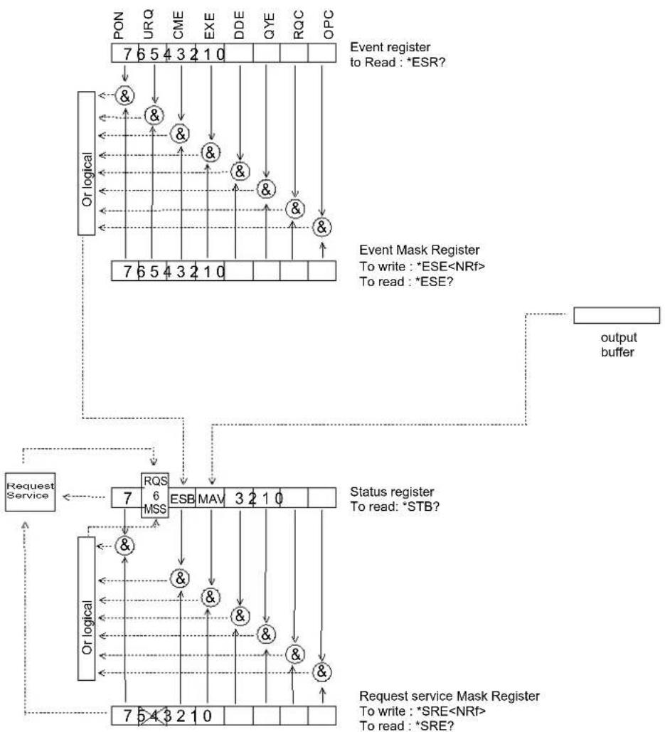
Events and status management
Registers
flowchart
graph TD
    subgraph_Event_Register_to_Regulation["Event register to Read: *ESR?"]
        PON["7 6 5 4 3 2 1 0"] --> OR_OGICAL["Or logical"]
        URO["URQ"] --> OR_OGICAL
        CME["CME"] --> OR_OGICAL
        EXE["EXE"] --> OR_OGICAL
        DDE["DDE"] --> OR_OGICAL
        QYE["QYE"] --> OR_OGICAL
        ROC["ROC"] --> OR_OGICAL
        OPC["OPC"] --> OR_OGICAL
    end

    OR_OGICAL --> RQS["RQS 6 MSS"]
    RQS --> ESB["ESB MAV 3 2 1 0"]
    ESB --> MSA["MSS"]
    MSA --> RQS
    RQS --> OR_OGICAL
    OR_OGICAL --> Request_Service["Request Service"]
    RQS --> OR_OGICAL
    OR_OGICAL --> Request_Service
    RQS --> Status_Register["Status register To read: *STB?"]
    RQS --> Request_Service
    Status_Register --> Request_Service
    Request_Service --> Request_Service
    Request_Service --> Request_Service
    Request_Service --> Request_Service
    Request_Service --> Request_Service
    Request_Service --> Request_Service
    Request_Service --> Request_Service
    Request_Service --> Request_Service
    Request_Service --> Request_Service
    Request_Service --> Request_Service
    Request_Service --> Request_Service
    Request_Service --> Request_Service
    Request_Service --> Request_Service
    Request_Service --> Request_Service
    Request_Service --> Request_Service
    Request_Service --> Eventarker["Event Mask Register To write: *ESE<NRf> To read: *ESE?"]
    Eventarker --> OutputBuffer["output buffer"]
Status registers
Reading only → *STB? common command.
In this case, the (MSS) 6 Bit is returned and remain in the status it was before reading [see §.*STB (Status Byte)]
The *CLS common command is reset to zero.
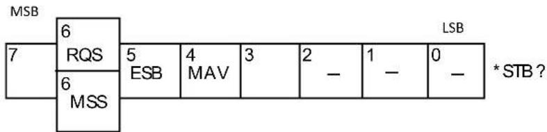
Detailed description
text_image
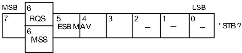
MSB 7 6 RQS 5 ESB 4 MAV 3 2 - 1 - 0 - 6 MSS LSB * STB ?RQS Request Service (6 bit)
Indicates if the instrument requests a service. The type of COMM used on the instrument does not generate a request, but the byte is accessible in reading. It is reset to 0 after reading and can switch to zero only if the event register is reset to zero (by reading or *CLS).
MSS Master Summary Status (6 bit)
Indicates if the instrument has a reason to request a service. This information is accessible only in reading the status register. (*STB? command) and stays as it is after the reading.
ESB Event Satus Bit (5 bit)
Indicates if at least one of the conditions of the event register is satisfied and not masked.
MAV Message Available (4 bit)
Indicates if at least one response is in the output spooler.
Service request mask register
Reading and writing → *SRE command.
MSB
LSB
| 7 6 5 | 4 3 2 1 | 0 | SRE*SRE? | |||||
| ESB | MAV |
Event register
Reading → *ESR command. Its reading resets to zero.
Detailed description
MSB
LSB
| 7 6 5 | 4 3 2 | 1 0 | |||||
| PON | URQ | CME | EXE | DDE | QYE | RQC | OPC |
PON Power On (7 bit)
Not used
URQ User request (6 bit)
Not used
CME Command Error (5 bit)
A command error has been detected.
EXE Execution Error (4 bit)
An error execution has been detected.
DDE Device Dependant Error (3 bit)
An error specific to the instrument has been detected.
QYE Query Error (2 bit)
A query error has been detected.
RQC Request Control (1 bit)
Always at zero.
OPC Operation Complete (0 bit)
All operations running are ended.
Event mask register
Reading and writing → *ESE command.
MSB
LSB
| 7 6 | 5 4 3 2 | 1 0 | |||||
| PON | URQ | CME | EXE | DDE | QYE | RQC | OPC |
ESE
IEEE 488.2 Commands
\*CLS
(Command)
(Clear Status)
The common command *CLS reset the status and event register.
\*ESE
(Command/Query)
(Event Status Enable)
The *ESE
A 1 authorises the corresponding bit of the event register to generate an event, while a 0 masks it.
To the question *ESE?, the instrument returns the current content of the event mask register.
Response format:
value in format
Event mask register :
MSB
LSB
| 7 6 | 5 4 | 3 2 1 | 0 | ||||
| PON | URQ | CME | EXE | DDE | QYE | RQC | OPC |
\*ESR?
(Query)
(Event Status Register)
To the question *ESR?, the instrument returns the content of the event register.
Once the register has been read, the content value is reset to zero.
Response format:
value in format
Event register
MSB
LSB
| 7 6 | 5 4 | 3 2 1 | 0 | ||||
| PON | URQ | CME | EXE | DDE | QYE | RQC | OPC |
\*IDN?
(Query)
(Identification Number)
To the question *IDN?, the instrument returns the type of instrument and the software version.
Response format:
\*OPC
(Command/Query)
(Operation Complete)
The command *OPC authorises the setting to 1 of the OPC bit in the event register as soon as the current operation is completed.
To the question *OPC?, the instrument returns the character ASCII "1" as soon as the current operation is terminated.
\*RST
(Command)
(Reset)
The command *RST reconfigures the instrument with the factory settings.
\*SRE (Command/Query)
(Service Request Enable)
The command *SRE
A value of bit at 1 enables the same-rank bit of the status register to request a service (bit of the status register contains 1). A bit value at 0 neutralizes it.
To the question *SRE?, the instrument returns the value of the service demand mask register.
Response format:
value in format
Service demand mask register :
MSB
LSB
| 7 6 5 | 4 3 2 1 | 0 | |||||
| 0 0 ES | B MAV | 0 0 0 0 |
\*STB? (Query)
(Status Byte)
To the question *STB? the instrument returns the content of its status register (Status Byte Register).
The bit 6 returned indicates the MSS value (Master Summary Status) (at 1 if the instrument has a reason for requesting a service).
Contrary to RQS, it is not reset to zero after reading the status register (RQS is accessible only by series recognition, and falls to 0 at its end).
Status register
text_image
MSB 6 7 RQS 5 4 3 2 1 0 * STB ? ESB M AV - - - - 6 MSS LSB * STB ?\*TRG (Command)
The command *TRG starts an acquisition in the current mode "single" or "continuous".
\*TST? (Query)
(Test) To the question *TST?, the instrument returns the status of the autotest procedure.
Response format: <0|1>
■ responds 0 when the autoset is successful.
■ responds 1 when a problem has been detected.
\*WAI (Command)
(Wait) The command *WAI prevents the instrument from performing further commands as long as the current command has not been terminated. This enables to synchronize the instrument with the application program in progress on the controller.
Tree structure
IEEE 488.2 Common commands
Commands Functions
| *CLS | Resets the status and event registers |
| *ESE | Writes event mask |
| *ESE? | Reads event mask |
| *ESR? | Reads event register |
| *IDN? | Reads identifier |
| *OPC | Validates bit OPC |
| *OPC? | Waits till end of execution |
| *RST | Resets |
| *SRE | Writes service request mask |
| *SRE? | Reads service request mask |
| *STB? | Reads status register |
| *TRG | Starts an acquisition in the current mode |
| *TST? | Returns the status of the autoset procedure |
| *WAI | Commands synchronization |
12. ANNEXES
line
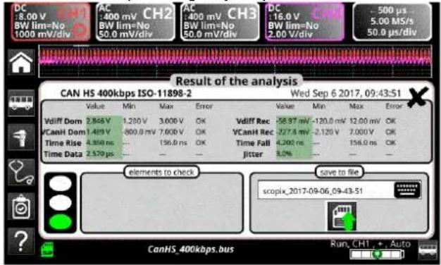
| Time Interval | Value | | ------------- | ----- | | Low | ON | | 1/2 bit | High | | High | High | | 10% HIGH | High | | Time Rise | Low | | Time Fall | Low |12.3.3. Mesures (CAN High-Speed)
text_image
DC :8.00 V BW lim=No 1000 mV/div AC :400 mV CH2 BW lim=No 50.0 mV/div AC :400 mV CH3 BW lim=No 50.0 mV/div DC :16.0 V BW lim=No 2.00 V/div -500 µs 5.00 MS/s 50.0 µs/div Result of the analysis CAN HS 400kbps ISO-11898-2 Wed Sep 6 2017, 09:43:51 Value Min Max Error Value Min Max Error Vdiff Dom 2.846 V 1.200 V 3.000 V OK Vdiff Rec -58.97 mV -120.0 mV 12.00 mV OK VCanH Dom 1.489 V -800.0 mV 7.608 V OK VCanH Rec -277.8 mV -2.120 V 7.000 V OK Time Rise 4.350 ns ... 156.0 ns OK Time Fall 4.200 ns ... 156.0 ns OK Time Data 2.579 µs ... ... Jitter 3.0% Save to file elements to check scopix_2017-09-06_09-43-51 Run, CH1 +, Auto CanHS_400kbps.bus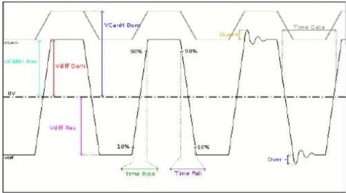
line
| Signal | Value | |-----------------|-------| | VCanH | 90% | | VCanH+ Res | 50% | | Vdiff Dom | 10% | | Vdiff Rec | -10% | | Over | Over |12.4.3. Mesures (Can Low-Speed)

text_image
DC 16.0 V CH1 AC 400 mV CH2 AC 400 mV CH3 DC 16.0 V Cmax 100 µs BW lim=No BW lim=No BW lim=No BW lim=No 2.00 V/div 25.0 MS/s 10.0 µs/div 2.00 V/div 50.0 mV/div 50.0 mV/div 2.00 V/div 10.0 µs/div Result of the analysis CAN LS 125Kbps ISO-11898-3 Mon Sep 4 2017, 13:42:25 Value Min Max Error Value Min Max Error Vdiff Dom 2.698 V 2.200 V 5.000 V CX Vdiff Rec -4.937 V -5.000 V -4.400 V CX VCanH Dom 3.837 V 3.600 V 5.000 V CX VCanH Rec -4.945 mV 0.000 V 300.0 mV CX Time Rise 210.6 ns — 1.500 µs CX Time Fail 192.6 ns — 1.506 µs CX Time Data 8.148 µs — — — elements to check save to file scopix_2017-09-04_13-42-25 CanLS_125Kbps.bus Ready_CH1 + Auto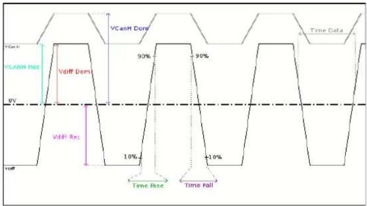
other
| Wave Type | Description | Value Label | | --------------- | ------------------- | ----------- | | VCanH Res | Vdiff Dem | 90% | | VCANH Res | Vdiff Rec | -10% | | Time Rise | Time Rise | 10% | | Time Fall | Time Fall | -10% |other
| Phase | Value | |-------------|-------| | High | 90% | | Low | 10% | | Pulse Width | 10% |line
| Time Series | Value | | ----------------- | --------- | | High | V High | | Low | V Low | | Time Rise | 10% | | Time Fall | 10% | | Distortion | 90% | | Distortion | 90% |line
| Time Period | Percentage | | ----------- | ---------- | | 0V | 90% | | 10V | 10% | | Time Rise | -10% | | Time Fall | -10% | | Time Data | 90% |other
| Time Interval | Value | | ----------------- | --------- | | High | High | | High | 90% HIGH | | High | 90% LOW | | Low | Low | | Low | Time Rise | | Low | Time Fall |line
| Time Data | Distortion | Noise Ripple | | --------- | ---------- | ------------ | | 90% | +10% | Yes | | 10% | +10% | Yes |text_image
DC 140.0 V BW lim=No 5.00 V/div AC 400 mV CH2 BW lim=No 50.0 mV/div AC 400 mV CH3 BW lim=No 50.0 mV/div DC 40.0 V BW lim=No 5.00 V/div 1.00 ms 2.50 MS/s 100 μs/div Result of the analysis RS485 19200bps >4V EIA-485 Wed Sep 6 2017, 08:11:47 VOffset Value Min Max Error V Level Value Min Max Error 4.169 V -7.000 V 12.00 V OK 7.022 V 400.0 mV 12.00 V OK Time Data 52.29 μs Time Rise 15.62 μs 15.62 μs OK Time Fall 50.00 ns Jitter 0.1% 5.0% OK Over+ 44.9% Over+ 10.0% +34.9% Over- 45.0% 10.0% +35.0% elements to check Save to file Unsuitable or damaged cable scopix_2017-09-06_08-11-47 Bus termination problem Significant noise RS485_19200bps.bus Run, CH1 +, Auto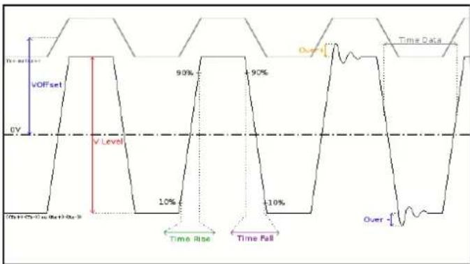
line
| Time | Value | |------|-------| | VOFFset | 90% | | v Level | 10% | | Time Rise | -10% | | Time Fall | -10% |text_image
DC 18.00 V BW lim=No 1000 mV/div F2 AC 400 mV CH3 BW lim=No 50.0 mV/div DC 8.00 V CH3 BW lim=No 1000 mV/div - 5.00 µs 500 MS/s 500 ns/div Result of the analysis USB low speed Value Min Max Error Value Min Max Error VHigh 4.439 V 1.000 V 3.600 V +838.9 mV VLow -1.878 V -3.600 V -1.000 V OK Time Rise 28.75 ns 75.00 ns 300.0 ns -51.25 ns Time Fall 23.45 ns 75.00 ns 300.0 ns -51.55 ns TRise-TFall 160.3 ns --- --- --- Time Data 834.4 ns --- --- --- Jitter 50.1% --- 24.0% +26.1% elements to check scopix_2017-09-19_10-16-37 Termination problem Faulty junction connection Cable length not compliant with standard Significant noise USB_LowSpeed.bus Ready, CH1 , + , Auto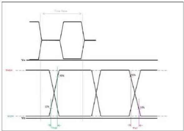
line
| Wave | Voltage | Current | |------|---------|---------| | Top | 90% | -10% | | Top | 10% | -2% | | Top | 30% | -3% | | Top | 50% | -10% | | Top | 70% | -2% | | Top | 90% | -3% | | Bottom | 90% | -10% | | Bottom | 10% | -2% | | Bottom | 30% | -3% | | Bottom | 50% | -10% | | Bottom | 70% | -2% | | Bottom | 90% | -3% |Our international contacts
www.chauvin-arnoux.com/contacts

CHAUVIN®
ARNOUX
CHAUVIN ARNOUX GROUP