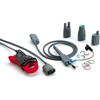
PROBIX - Measuring equipment METRIX - Free user manual and instructions
Find the device manual for free PROBIX METRIX in PDF.


| Product Type | Current clamp for oscilloscope with Hall effect sensor |
| Brand | Metrix |
| Model | PROBIX (accessory HX0034B) |
| Dimensions | 138 x 49 x 28 mm |
| Weight | Approx. 160 g |
| Power Supply | Powered by the oscilloscope via connecting cable, 4 VDC / 23 mA |
| Nominal Range | 80 A peak (57 A RMS) |
| Output/Input Ratio | 20 mV/A |
| Bandwidth | 500 kHz @ -1dB / 1 MHz @ -3dB |
| Resolution | 10 mA |
| Error (0-45 A peak) | ± 1.5 % ± 10 mA |
| Error (45-80 A peak) | ± 4 % |
| Output voltage at zero current | ± 0.3 mV DC (i.e. ± 15 mA DC) |
| Main Functions | Measurement of DC or AC current up to 80 A peak, isolated output, automatic zero (offset) compensation |
| Maintenance and Cleaning | Clean the air gaps with a soft lint-free cloth; housing with a cloth and soapy water, rinse, dry. Do not immerse. |
| Safety | Double insulation, cat. II 600V / cat. III 300V, do not use on uninsulated conductors at potential >600V, avoid high frequency currents >4 Aeff @ 1 MHz |
| Spare Parts and Repairability | Annual calibration check by an approved organization. No spare parts mentioned. |
| General Information | User manual in French, 17 pages, available for download. Brand Metrix, model PROBIX. |
Frequently Asked Questions - PROBIX METRIX
User questions about PROBIX METRIX
0 question about this device. Answer the ones you know or ask your own.
Ask a new question about this device
Download the instructions for your Measuring equipment in PDF format for free! Find your manual PROBIX - METRIX and take your electronic device back in hand. On this page are published all the documents necessary for the use of your device. PROBIX by METRIX.
USER MANUAL PROBIX METRIX
natural_image
Line drawing of a mechanical device with no visible text or symbolsPINCE AMPEREMETRIQUE
AMMETER CLAMP
ZANGEN AMPEREMETER
PINZA AMPEROMETRICA
PINZA AMPERIMETRICA
ProbiX
Français
1. Généralités
The HX0034B accessory is a current clamp for oscilloscopes using a Hall-effect cell to measure DC or AC currents up to 80 A peak, without any intervention on the electrical installation. This clamp, which is a voltage output transducer, is a PLUG and PLAY device used as an accessory for the Scopix portable oscilloscopes. Its internal electronics is supplied by the oscilloscope, via the power supply cord. The measurement output is totally insulated.
2. Safety
Never perform measurements on conductors with a potential greater than 600 V in relation to the earth. This clamp is protected by double insulation or reinforced insulation. It does not have to be connected to the earth protection terminal for electrical safety. This clamp is designed for indoor use at an altitude < 2,000 m in an environment with pollution level 2. This clamp can be used for measurements on Cat. II installations up to 600 V and on Cat. III installations up to 300 V. Do not use this clamp on conductors carrying high-frequency currents greater than 4 A rms @ 1 MHz : risk of burning and deformation of the clamp jaws. The protection ensured by this clamp can be compromised if it is used in a way which is not specified.
3. Functional description
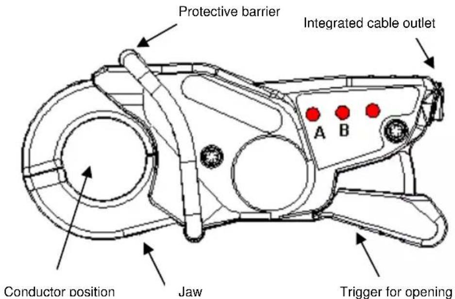
text_image
Protective barrier Integrated cable outlet A B Conductor position Jaw Trigger for openingThere are three pushbuttons on the side of the clamp:
- Pushbuttons A and B can be programmed using the vertical menu of the SCOPIX oscilloscope to activate commands. Example: incrementation/decrementation of the vertical sensitivity, the time base, display of the automatic measurements, etc. Refer to the user's manual of the SCOPIX oscilloscope.
- The "Offset" automatically calibrates the zero DC of the clamp. The end of this process is indicated by an audio "beep" from the oscilloscope. In "Multimeter" mode, SCOPIX eliminates the residual current.
4. Implementation
- Do not use the clamp outdoors.
- Do not exceed 300 V (Cat. III) or 600 V (Cat. II) in relation to the earth of a non-insulated conductor (double insulation).
- Use the clamp on conductors in which the current is less than or equal to the maximum value in continuous operation, i.e. 80 A peak.
- Protect the clamp against falls and splashing with water.
5. Use
-
This clamp must be connected to the associated oscilloscope before performing any current measurements. It must not be disconnected during measurement.
-
Connect the clamp to the oscilloscope: it is recognized by the instrument and the unit is displayed in A/div. on the SCOPIX oscilloscope's screen.
-
Adjust the offset by pressing the "Offset" button. The offset can be performed only without current. However, the presence of a DC current is accepted. In this case, the offset will be performed in relation to this initial current.
-
Use the trigger to open the jaws of the clamp and then place them around the conductor, taking into account the current direction.
-
Close the clamp. Make sure that it is properly closed and centred on the conductor for optimum measurement accuracy.
6. Specifications
■ Reference conditons
| Parameter | Reference conditions |
| Power supply voltage | 4 VDC ± 13 % external 23 mA |
| Start-up before measurement | 1 minute |
| Ambient temperature | 23°C ± 5°C |
| Humidity | 20 % RH to 75 % RH |
| Frequency | DC at 400 Hz |
| Conductor position | centred in jaws |
| External AC magnetic field | no field |
| External DC magnetic field | < 40 A/m (earth field) |
| Measuring device impedance | 1 MΩ and C < 100 pF |
Values
| Parameters | Value | |
| Nominal calibre | 80 A peak (or 57 A RMS) | |
| Input/output ratio | 20 mV/A | |
| Resolution | 10 mA | |
| Error in % of measurement | 0 to 45 A peak (or 31.8 A RMS) ± 1.5% ± 10 mA | 45 to 80 A peak ± 4% |
| Phase error at 50 Hz | 0 to 45 A peak (or 31.8 A RMS) ± 1^ | 45 to 80 A peak ± 1^ |
| Bandwidth | 500 kHz @ -1dB or 1 MHz @ -3dB | |
| Derating in frequency (*) | 40 A RMS max. @ 100 kHz - 8 A RMS max. @ 0,5 MHz4 A RMS max. @ 1 MHz | |
| Rise time | 350 ns from 10 to 90 % | |
| Output voltage for Ip = 0 (**) | ± 0.3 mVdc i. e. ± 15 mAdc | |
| Power supply current | typically 23 mA (20 to 25 mA) | |
(*) Ambient temperature : 40°C max.
(**) after zero offset
■ Mechanical specifications
Dimensions : 138 x 49 x 28 mm
Weight : approx. 160 g
■ Environmental conditions
Operating temperature (clamp only) : -10°C to +55°C
■ Safety compliance
IEC 61326-1 EMC
IEC 61010-2-032 : Safety rules
7. Maintenance
Before any maintenance operations, the clamp must be disengaged from the conductor and must be disconnected from the external device to which it is linked.
- Maintenance of the magnetic circuit
Keep the clamp jaws as clean as possible. If necessary, clean them using a soft, lint-free cloth.
- Cleaning of the casing
Clean the clamp with a cloth and soapy water. Rinse off with a cloth moistened with clean water. Never allow the clamp to come into contact with water. Dry using a dry cloth or pulsed air (max. temperature +70°C).
- Calibration verification
Annual verification of the measurement characteristics by an approved organization.
1. Beschreibung
Our international contacts
www.chauvin-armoux.com/contacts

CHAUVIN® ARNOUX
CHALVIN GROUP