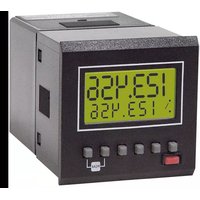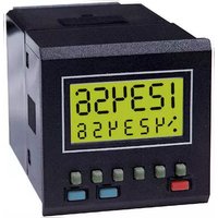
7932 - Measuring equipment Trumeter - Free user manual and instructions
Find the device manual for free 7932 Trumeter in PDF.


User questions about 7932 Trumeter
0 question about this device. Answer the ones you know or ask your own.
Ask a new question about this device
Download the instructions for your Measuring equipment in PDF format for free! Find your manual 7932 - Trumeter and take your electronic device back in hand. On this page are published all the documents necessary for the use of your device. 7932 by Trumeter.
USER MANUAL 7932 Trumeter
text_image
888888 : I 0 0 0 0 0 0 0 × RST PRG SEL
c US CE 7932
WARNING: Read page 32 first.
6 digit programmable counter / timer relay, with prescaling and EEPROM data storage
English
Page 2
Black on green STN LCD, with
yellow/green LED backlight.
Program Storage
Erase/write cycles:1,000,000
Life: 40 years min
Count Range
0 to 999999
Count Pre-scaler
Multiplier 0.00250 to 9.99999
Divider 1 to 99999
Timing Range - see page 7
Timing Accuracy ± 0.3%
Inputs (see Inputs)
High Speed: 10kHz max (electronic)
Duty cycle: 60:40 max
Low Speed: 30Hz max (contact closure)
External Reset response time
Max 2mSec
Relay Contacts (see Relays)
UL Ratings
AC 250V max, DC 125V max
250V AC: 16 HP max
30V DC: 5A max
General ratings
AC 1250VA max, 300V AC max
250V AC (cosø =1): 5A max
250V AC (cosø =0.4): 3A max
DC 150W max, 220V DC max
30V DC: 5A max
5A resistive load 100,000 operations
2A resistive load 1,000,000 operations
Reaction time: <20ms.
Supply (see Connections)
94 to 240V AC ± 10% 50/60Hz
VA Rating 4VA
or 12 to 24VDC ± 10%
typical current 100mA DC (max)
Installation Category (IEC 664)
Overvoltage category II
(Pollution degree 2)
Operating temperature
-10^ to +60^
Storage temperature
-20^ to +70^
Environmental protection
IP65 (panel mounting) using the sealing gasket supplied (without Screw-fixed bezel). If the seal is removed, it must be replaced with a new one.
See page 39 for cut-out dimensions
Altitude
Up to 2000m
Relative Humidity
80% max up to 31°C, decreasing to 50% max at 40°C
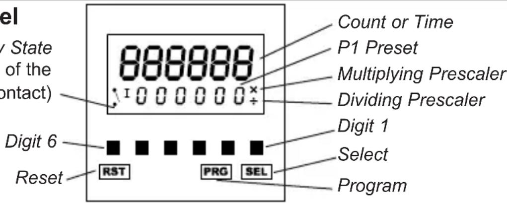
The Front Panel
Relay State
(showing the state of the normally open contact)
text_image
Level ( v State of the contact ) 888888 Count or Time P1 Preset Multiplying Prescaler Dividing Prescaler Digit 6 Reset ■ ■ ■ ■ ■ ■ ■ RST PRG SEL Select ProgramThe front panel buttons are used to program the counter and to display and set the P1 preset. All the buttons can be disabled by the Keyboard Inhibit input. (see Programming on page 6).
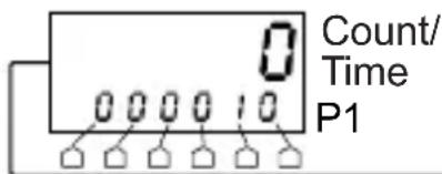
P1 Preset
The P1 preset can be set at any time. The minimum value possible is 000001. P1 must be greater than any multiplying prescaler value, or the unit may not operate correctly.
text_image
0 Count/ Time P1
text_image
SEL P1 0 0 0 0 0 5 P1 SELPress SEL, then use the Digit buttons to change P1. The display will flash. Press SEL again to accept the new value. If SEL is not pressed within 30 seconds of the last change, P1 will revert to the original value.
In Reset to Zero mode, the change will be accepted immediately.
In Reset to P1 mode, the change will not be accepted until after a Reset.
Auto Reset (see and on page 35 and on page 36)
When Auto Reset is on, the counter will be automatically reset as follows: In Reset to Zero mode, the counter will reset to zero when P1 is reached. In Reset to P1 mode, the counter will reset to P1 when zero is reached.
Front Panel Reset and External Reset (RST / Ext. Reset)
A Reset can be caused by pressing the RST button or by applying a signal to the External Reset input. Any active relay will be returned to its normal condition.
If the operation of the External Reset is safety critical, it is recommended that the External Reset signal is derived from an independent power supply which will remain stable if the 7932's supply is interrupted.
Counter Modes (see page 35)
The diagrams show how the Relay is controlled by the Count, and by RST/Ext. Reset. The diagrams show how the Count is controlled by the Input signal.
The diagrams show how the Count is reset to zero or P1 by Auto Reset. In all modes, the Count can be reset at any time by RST/Ext. Reset.
In Reset to Zero mode, the counter can count up to 999999. In Reset to P1 mode, the counter can count from P1 down to -99999. At these limits, the display will flash until RST/Ext. Reset.
1 Counter with Auto Reset on
Note: The relay cannot be set to Latched.
2 Counter with Auto Reset off
Note: If the relay is set to Latched, it will return to its normal condition at RST/Ext. Reset.
Timer Modes (see page 36)
The diagrams show how the Relay is controlled by the Timer, and by RST/Ext. Reset.
The diagrams show how the Time is controlled by the Input signal and by the Pause setting.
The diagrams show how the Time is reset to zero or P1 by Auto Reset. In all modes, the Time can be reset at any time by a RST/Ext. Reset.
In Reset to Zero mode, the timer can time up to 999999. In Reset to P1 mode, the timer can time from P1 down to zero.
1, 2imer with Pause enabled
Note: When the Input signal is removed, timing stops. When the Input signal is re-applied, the unit continues to time from this previous value.
3, 4imer with Pause disabled
Note: When the Input signal is removed, timing stops. When the Input signal is re-applied, the unit resets to zero or P1, and starts timing from this value.
- Timer with Auto Reset on
Note: The relay cannot be set to Latched.
2, 4Timer with Auto Reset off
Note: On reaching P1, timing will stop, but a RST/Ext. Reset will restart it.
Note: If the relay is set to Latched, it will return to its normal condition at RST/Ext. Reset.
| Pin | Description Range | |
| 1 | Auxiliary DC Supply -ve | 0V - See pin 2, below |
| 2 | Auxiliary DC Supply +ve | Power Supply (see pages 37 & 38)The counter can be powered by AC mains, in which case pins 1 and 2 provide an Auxiliary supply (+12V DC +20%-10%, 75mA max recommended) which can be used to power sensors if required. Alternatively, the counter can be powered by an external DC source (12-24V DC ±10%, 100mA), connected to pins 1 and 2. |
| 3 | 4/5 Common See Input Polarity, page 5 | |
| 4 | External Reset Input  [2480](Input R) [2480](Input R) | Opto-isolated, 12-240 V ±10% DC or 50/60Hz ACSee Specification, page 2 |
| 5 | Low Speed Counter/Timer Input [18C0] [DWBD](Input CT) | Opto-isolated, 12-240 V ±10% DC or 50/60Hz ACSee Specification, page 2This input can be used in Counter or Timer Mode |
| 6 | Neutral | 94 to 240VAC ±10% 50/60 Hz |
| 7 | Live | |
| 8 | Not used | ---- |
| 9 | ||
| 10 P1 | Normally Open contact | Isolated relay contacts50/60Hz 300V AC max, 220V DC max |
| 11 P1 | Common contact | |
| 12 P1 | Normally Closed contact | See Specification, page 2 |
| 13 | 14/15 Common See Input Polarity, page 5 | |
| 14 | Keyboard Disable Input (Input K)  [AYOX] [AYOX] | 5-30 VDC See Specification, page 2This input can be used to disable the front panel buttons, but only if configured by the Inhibit option.See Programming, page 6 |
| 15 | High Speed Counter Input (Input CH) | 5-30 VDC See Specification, page 2This input can be used in Counter Mode only |
High Speed Inputs

These are high speed inputs (10kHz max), suitable only for electronic signal sources, eg. transistors, proximity switches, encoders.
Low Speed Inputs


These are low speed inputs (30Hz max), suitable for contact closure sources, eg. microswitches, relays, pushbuttons. Any contact noise is removed by filtering. They can also be used for electronic signal sources.
Cables
Maximum wire size the connector can accept is:
2.5mm ^2 cross sectional area; 1.8mm diameter. (equivalent 13 AWG solid wire)

Any signal cables connected to this device must not exceed 30 metres in length.
If signal cables are installed that are routed outside the building, it will be necessary to install additional surge protection devices.
Input Polarity (see pages 37 and 38)
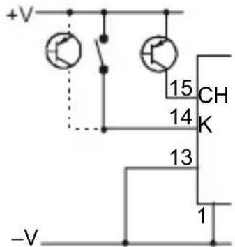
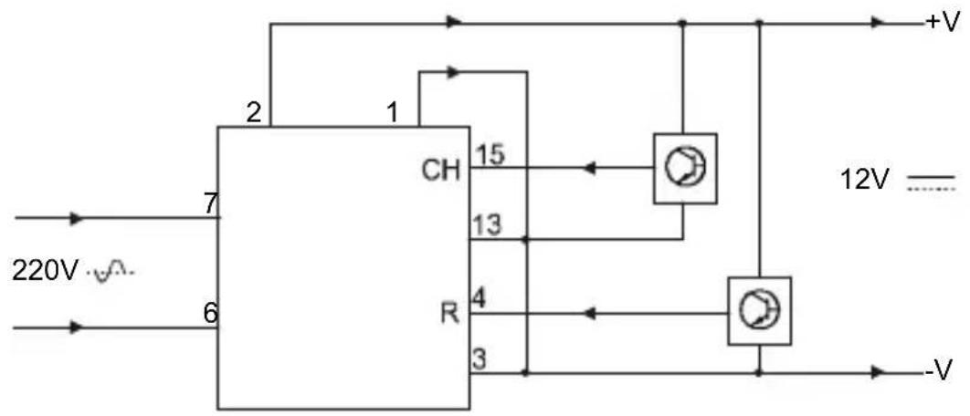
Inputs CH and K (pins 15 and 14) can be sink or source dc inputs, depending on the way they are wired, with respect to their Common input (pin 13), as shown in the examples below, and on pages 37 and 38. Pin 1 must always be connected as shown.
The opto-isolated inputs CT and R (pins 5 and 4) can be sink or source ac or dc inputs, depending on the way they are wired, with respect to their Common input (pin 3), as shown in the examples below and on pages 37 and 38.
Only CT and R are isolated from the supply pins.
Sink (NPN) Inputs
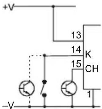
text_image
+V 13 14 K CH 15 -V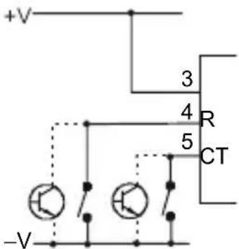
text_image
+V 3 4 R 5 CT -VSource (PNP) Inputs
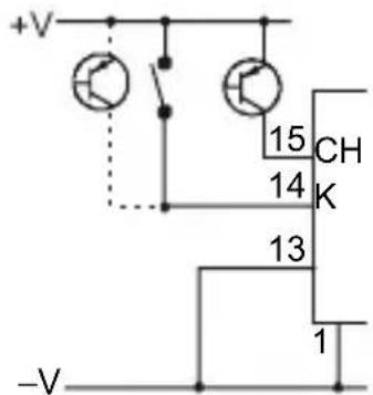
text_image
+V 15 CH 14 K 13 1 -V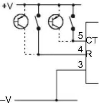
text_image
+V 5 CT 4 R 3 -VNote: Common Pins 13 and 3
These pins must always be correctly connected for their inputs to work.
For dc signals, to +V or -V, as shown in the examples above and on page 37.
For ac signals (5/4/3 only), as shown in examples 3 and 4 on page 37.
Count and Timing Direction
In all modes, count and timing direction is dependent on Reset mode (see Programming). Either Input CH or Input CT can be used in Counter mode, but only Input CT can be used in Timer mode (see Programming).
The count direction and the edges that trigger the count are shown by the arrows:
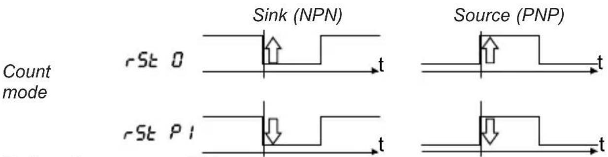
Relay (see page 38)
This is a single pole double throw relay, with a common contact, a normally open contact, and a normally closed contact. The Relay State indicator on the front panel shows the state of the normally open contact.
The relay can be programmed to operate in pulsed or latched mode. In pulsed mode the relay will operate for a length of time set by the program. In latched mode (Auto Reset Off only) the relay will operate, and stay in that condition until RST/Ext. Reset.
The relay can be programmed to revert to a known safe state in the event of a power failure or on entering program mode. The three alternatives are:
Current - the contacts will remain in the same state as before the event;
Reset - the contacts will revert to their normal, unoperated state;
Set - the contacts will revert to their operated state.
Programming
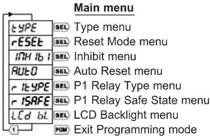
- To enter Programming mode, press and hold PGM for 3 seconds. The display counts down 3..2..1.
text_image
Main menu TYPE rESET INH ib i AUTO r itype r ISAFE LCD bl SEL Type menu SEL Reset Mode menu SEL Inhibit menu SEL Auto Reset menu SEL P1 Relay Type menu SEL P1 Relay Safe State menu SEL LCD Backlight menu PGM Exit Programming mode- Press Digit 1 to cycle through the menus, or PGM to exit Programming mode.
- Press SEL to select a menu, then Digit 1 to cycle through the options.
- Press SEL to select an option, or PGM to exit the menu without change.
- Press the Digit buttons to adjust a numerical setting, eg. pulse time.
- Press SEL to accept the setting, or PGM to exit the setting without change.
- Press PGM (up to four times) to exit Programming mode.
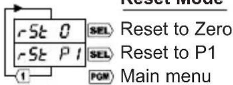
If the Type or Reset Mode are changed the new configuration will not be fully effective until after exit from Program mode, AND THEN AFTER a Reset.
Reset Mode
See page 3.
Inhibit
See page 2.
Auto Reset
See page 3.
Relay
See page 5.
* Auto Reset On and Relay Latched cannot be set together.
LCD Backlight:
can be on, off, or turn on for 30 seconds when a button is pressed.
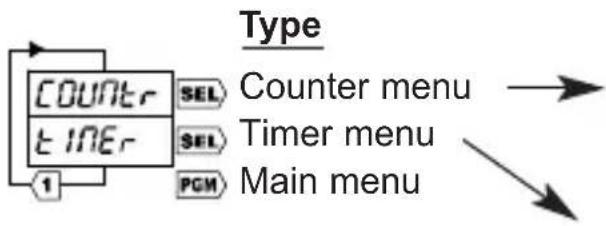
flowchart
graph TD
    A["Counter"] --> B["SEL"]
    C["TIME"] --> D["SEL"]
    E["PGM"] --> F["Main menu"]
    style A fill:#f9f,stroke:#333
    style C fill:#f9f,stroke:#333
    style E fill:#f9f,stroke:#333
    style B fill:#ccf,stroke:#333
    style D fill:#ccf,stroke:#333
    style F fill:#ccf,stroke:#333
text_image
Reset Mode rSt 0 SEL Reset to Zero rSt P1 SEL Reset to P1 PGM Main menu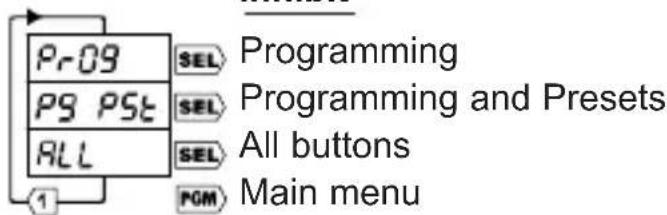
text_image
Pr09 SEL Programming PS PST SEL Programming and Presets ALL SEL All buttons PGM Main menu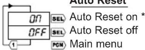
text_image
Auto Reset ON OFF SEL SEL PGM Auto Reset on * Auto Reset off Main menu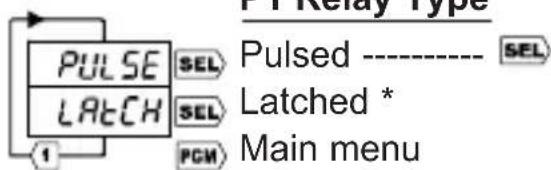
text_image
Pulse Latch 1 SEL SEL PCM Pulsed ---- SEL Latched * Main menu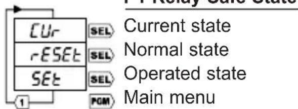
text_image
Current state Normal state Operated state Main menu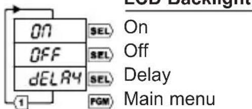
text_image
ON OFF DELAY 1 SEL SEL SEL FGM On Off Delay Main menu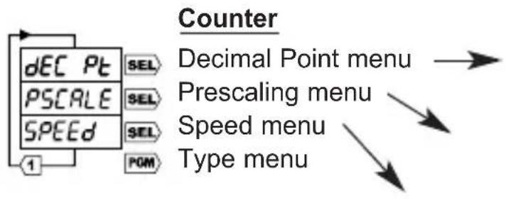
flowchart
graph TD
    A["Counter"] --> B["dEC Pt"]
    A --> C["PSCALE"]
    A --> D["SPEED"]
    A --> E["1"]
    B --> F["SEL"]
    C --> G["SEL"]
    D --> H["SEL"]
    E --> I["DOM"]
    J["Decimal Point menu"] --> K["Prescaling menu"]
    L["Speed menu"] --> M["Type menu"]
text_image
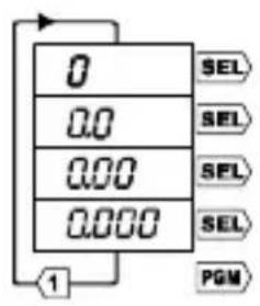
0 0.0 0.00 0.000 SEL SEL SEL SEL PGM 1Decimal Point No Decimal point 1 Decimal place 2 Decimal places 3 Decimal places Counter menu
Decimal Point
The decimal point can be in one of three positions, or off.
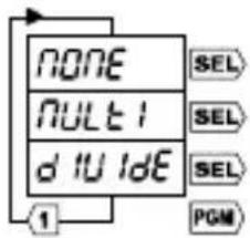
Prescaling
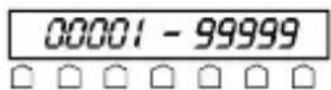
A multiplying or dividing factor can be used. If a multiplying prescaler of n is used, the counter will count: 0, n, 2n, 3n etc. If a dividing prescaler of n is used, the counter will increment or decrement on every nth input pulse.
Changes in the prescaler are not effective until after exit from Program mode, AND THEN AFTER a Reset.
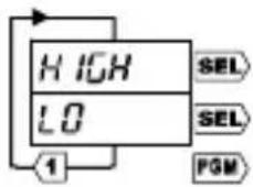
Speed
See page 4.
text_image
NONE MULT1 d 10 dE ① SEL SEL SEL PGMPrescaling
No prescaling
Multiply ---- SEL
Divide ---- SFL
Counter menu
Multiply

Divide
Speed
High Speed Input CH Low Speed Input CT Counter menu
flowchart
graph TD
    A["Base"] --> B["Timebase menu"]
    C["Pause"] --> D["Timebase menu"]
    E["PGM"] --> F["Type menu"]
    style A fill:#f9f,stroke:#333
    style C fill:#f9f,stroke:#333
    style E fill:#f9f,stroke:#333
    style B fill:#ccf,stroke:#333
    style D fill:#ccf,stroke:#333
    style F fill:#ccf,stroke:#333
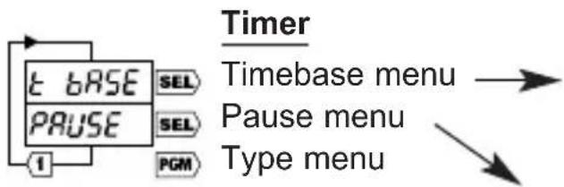
Timebase
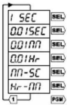
The Timer can measure real time, in six different sets of units.
Changes in the timebase are not effective until after exit from Program mode, AND THEN AFTER a Reset.
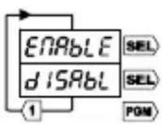
Pause
See page 3.
text_image
1 SEC 0.01SEC 0.01NN 0.01Hr NN-SC Hr-NN ① SEL SEL SEL SEL SEL SEL PGMTimebase
Seconds
Seconds/100
Minutes/100
Hours/100
Minutes & Seconds
Hours & Minutes
Timer menu
text_image
ENABLE DISABLE SEL SEL PGMPause
Pause enabled
Pause disabled
Timer menu
Spezifikation
Anzeige
text_image
Sink (NPN) rSt 0 t Source (PNP) rSt PI ttext_image
1 SEC 0.01SEC 0.01NO 0.01Hr NO-SC Hr-NO ① SEL SEL SEL SEL SEL SEL SEL PGMZeitbasis
text_image
ENABLE d ISABL 1 SEL SEL PGMPausa
Pausa habilitada
Pause deshabilitada
Menú temporizador
Specifiche
Display
Ingressi Source (PNP
text_image
+V 15 CH 14 K 13 1 -V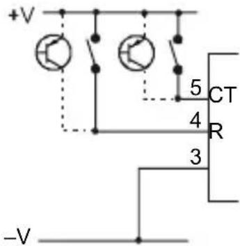
text_image
+V 5 CT 4 R 3 -VNota: Pin Comuni 13 e 3
text_image
1 SEC 0.01SEC 0.01NN 0.01Hr 00-SC Hr-NO ① SEL SEL SEL SEL SEL SEL PGMMenu Base Tempi
Secondi
Secondi/100
Minuti/100
Ore/100
Minuti e secondi
Ore e minuti
Menu Timer
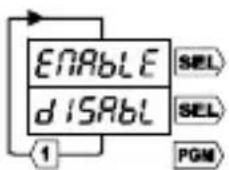
Pausa
Pausa abilitata
Pausa disabilitata
Menu Timer

WARNING
INSTALLATION AND MAINTENANCE MUST BE CARRIED OUT BY SUITABLY QUALIFIED PERSONNEL ONLY. HAZARDOUS VOLTAGES MAY BE PRESENT ON THE CONNECTION TERMINALS.
Installation
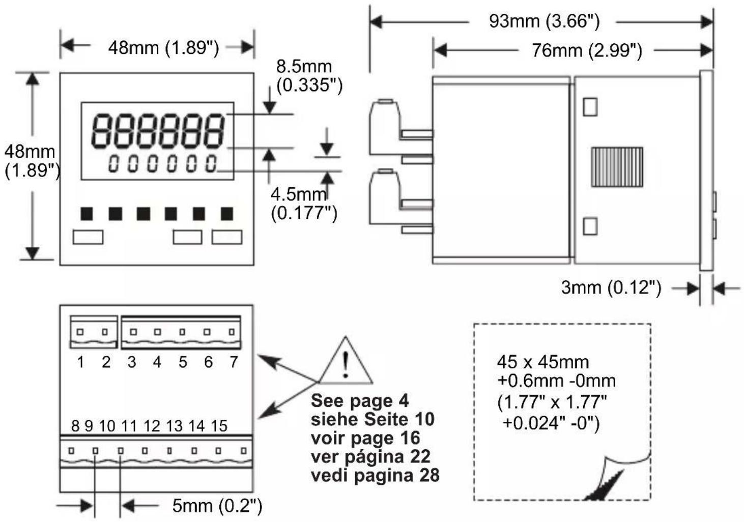
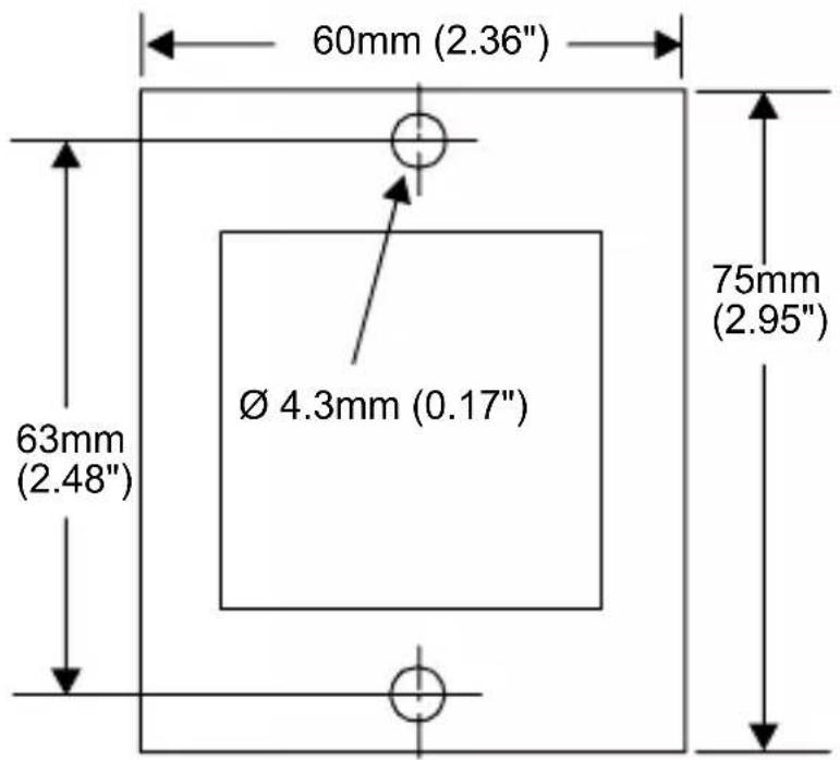
This product is intended to be installed in accordance with the operating and installation requirements of Overvoltage Category II and Pollution Degree 2 (as defined by IEC 664). It must be fitted in a suitable enclosure which is accessible to qualified personnel only. See page 39 for panel cut-out dimensions.
When using an AC supply to power the unit a suitable fuse must be used. The recommended fuse is type - S504-250mA manufactured by Bussmann.
Fuse details: Antisurge 250mA, Rating 250VAC, Breaking capacity 35A @250VAC, UL recognised (file no E75865), complies with IEC127.
The relay output circuits must be fitted with fuses suitable for the voltage and current being switched.
All conductors carrying hazardous voltage should have external switching or disconnect mechanisms fitted which provide at least 3mm of contact separation in all poles.
Failure to install or operate the unit in accordance with the above requirements may result in the electrical safety of the unit being impaired.
Maintenance
Ensure that all power sources to the unit are isolated prior to maintenance, inspection or cleaning.
There are no user serviceable parts inside this unit. Under no circumstances should the case be opened.
All external wiring connections should be inspected at regular intervals. Any damaged wiring should be replaced and any loose connections should be retightened.
Cleaning should be carried out using a dry cloth to wipe the casing of the unit.

ACHTUNG
text_image
1 1...2...3 rSt 0 rSt P1 P1 0 0 P1 0 P1 CT RST / R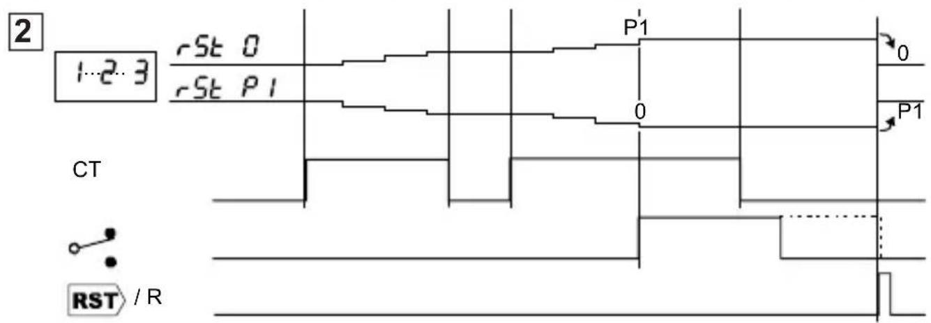
text_image
2 1-2-3 rSt 0 rSt P1 P1 0 0 P1 CT RST / R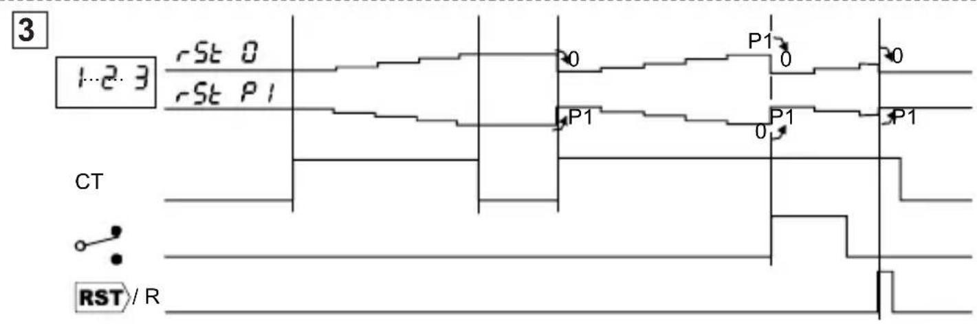
text_image
3 rSt 0 1..2..3 rSt P1 P1 P1 P1 CT RST / R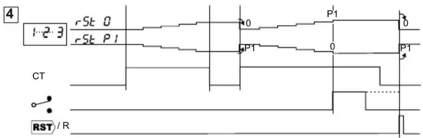
text_image
4 rSt 0 1-2-3 rSt P1 P1 0 P1 0 P1 CT RST / RInput examples, Anschlussbeispiele, Exemples d'Entrées, Ejemplos de entrada, Esempi di ingresso
1
flowchart
graph TD
    A["220V"] --> B["7"]
    B --> C["6"]
    C --> D["2"]
    D --> E["1"]
    E --> F["CH"]
    F --> G["15"]
    F --> H["13"]
    F --> I["R"]
    I --> J["4"]
    I --> K["3"]
    L["12V"] --> M["+V"]
    N["-V"] --> O["-V"]
2
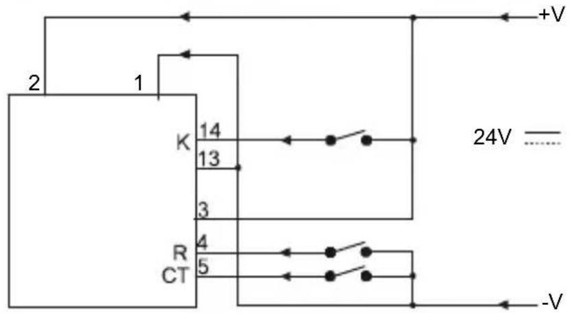
text_image
2 1 K 14 13 3 R CT 4 5 +V 24V -V3
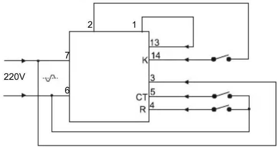
flowchart
graph TD
    A["220V"] --> B["7"]
    B --> C["K"]
    C --> D["13"]
    C --> E["14"]
    C --> F["3"]
    C --> G["5"]
    C --> H["4"]
    C --> I["CT/R"]
    style A fill:#f9f,stroke:#333
    style B fill:#ccf,stroke:#333
    style C fill:#cfc,stroke:#333
    style D fill:#fcc,stroke:#333
    style E fill:#cff,stroke:#333
    style F fill:#ffc,stroke:#333
    style G fill:#cfc,stroke:#333
    style H fill:#fcc,stroke:#333
    style I fill:#ffc,stroke:#333
4
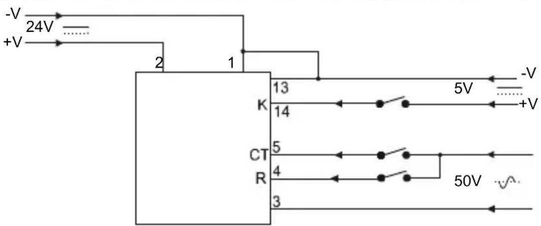
text_image
-V 24V +V 2 1 K 13 14 CT 5 4 3 5V -V +V 50VConnections, Anschlüsse, Connexions, Conexiones, Collegamenti
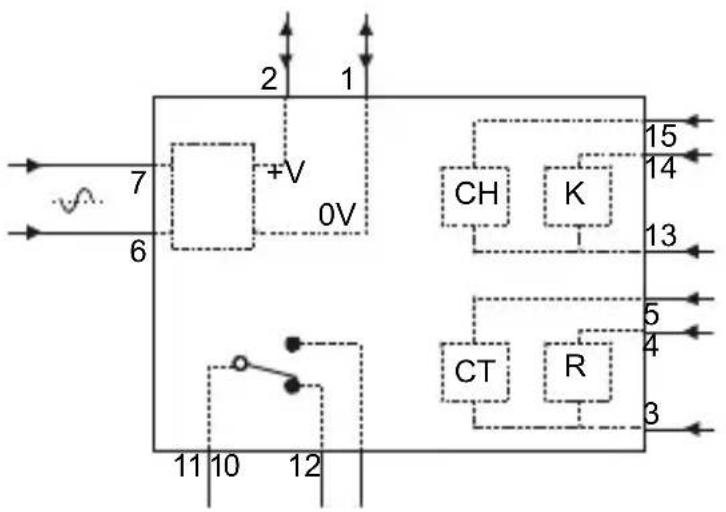
flowchart
graph TD
    A["7"] --> B["+V"]
    C["6"] --> B
    B --> D["0V"]
    E["15"] --> F["K"]
    G["14"] --> F
    H["13"] --> I["CH"]
    J["5"] --> K["CT"]
    L["4"] --> M["R"]
    N["3"] --> O["CT"]
    P["11"] --> Q["10"]
    R["12"] --> S["12"]
Relay examples, Beispiele Relaisanschlüsse, Exemples de Relais, Ejemplos de Relé, Esempi di relè

text_image
220V 7 6 11 12 10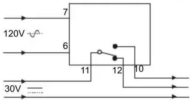
text_image
120V 7 6 11 12 10 30V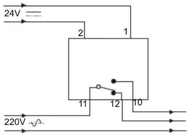
text_image
24V 2 1 11 12 10 220VDimensions, Abmessungen, Dimensiones, Dimensioni
Screw-fixed bezel, Frontrahmen mit Schraubenbefestigung, Cadre à vis, Marco fijado con tornillos, Cornice a vite
Fixing Clip, Befestigungs-klammer, Clip de fixation, Clip fijación, Fermaglio di fissaggio
text_image
60mm (2.36") Ø 4.3mm (0.17") 63mm (2.48") 75mm (2.95")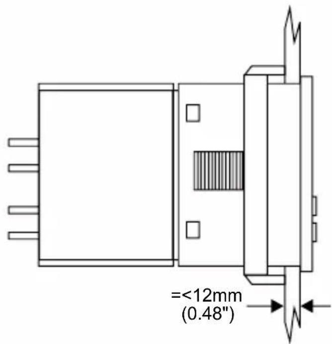
text_image
=<12mm (0.48"Trumeter Company Ltd, Milltown Street, Radcliffe, Manchester, M26 1NX, England
Tel: +44 (0)161 724 6311 Fax: +44 (0)161 724 9455
e-mail: sales.uk@trumeter.com
Trumeter Company Inc. (USA), 1020 North West 6 Street, Deerfield Beach, Florida 33442, USA
Tel: +1 954 725 6699 Fax: +1 954 725 5599
email: sales.usa@trumeter.com
Trumeter (Malaysia) Sdn. Bhd., Lot 2835, Lorong Perusahaan Lapan B, Kawasan Perusahaan Perai, 13600 Perai, Pulau Pinang, Malaysia
Tel: +604 3999 580 Fax: +604 3999 685
email: sales.malaysia@trumeter.com
Trumeter France, 99 rue Parmentier, BP 304, 59666 VILLENEUVE D'ASCQ CEDEX, France
Tel: +33 (0) 3 20 59 16 26 Fax: +33 (0) 3 20 59 16 27
email: ventes.france@trumeter.com
Trumeter Ireland, 9 Barrow Mews, Centaur Street, Carlow, Co. Carlow, Republic of Ireland
Tel: +353 (0)59 917 0777 Fax: +353 (0)59 917 0785
e-mail:sales.ireland@trumeter.com